From time to time it is necessary to replace the hydraulic distributor switch, as well as adjust the moment of automatic activation of the FDA drive. Between the drum and the pack of friction discs there is a piston, which in the non-working position is pressed against the drum, so the discs are released.
Due to a leak in the booster valve, the automatic spool return device operates at lower pressures.
The part needs to be replaced. The hydraulic distributor switch pusher rests against this cone, and in the described position of the coupling half, the switch contacts are open. In this case, the cold oil should be heated to temperature K, and the response pressure of the safety valve should be adjusted to MPa and the ball valve to .5 MPa.
Oil leakage to the outside through the rubber seals of the piston rod or pipeline fittings - Replace the rubber seals of the piston rod, tighten the pipeline fittings. Replace equipment, install pipelines with a large flow area, eliminate unnecessary bends, connections, etc.
Rapid wear and delamination of the front wheel tires. The toe adjustment of the front wheels is broken. Eliminate design defects, repair cylinder rods, etc. Replace seal.
In this mode, the hydraulic distributor is forcibly turned on, so oil is constantly supplied to the hydraulic coupling regardless of the direction of movement of the tractor. Replacing hydraulic filters MTZ 82.1 and MTZ 892 and replacing bearings on cultivator rollers
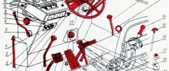
We recommend: How to connect a starter to an MTZ-80 diagram
Design and principle of the hydraulic system
The advantages of a tractor over other equipment are well known: versatility, the ability to work with different attachments and trailers. It is the hydraulic system that makes it possible to aggregate, that is, combine the tractor with mounted and semi-mounted working equipment, various trailers and semi-trailers equipped with hydraulic mechanisms. Due to oil pressure - the working fluid of the system - manipulation of all attachments is ensured: bulldozer blades, buckets, plows and harrows, organs for planting and harvesting. The basis of the hydraulic system is a hydraulic pump and a distributor.
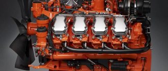
The pump creates the necessary pressure in the system, which makes it possible to control additional equipment and trailers. To avoid overload, it operates only at low engine speeds. The pump is located on the body of the hydraulic units, secured with studs, and centering is ensured by a special glass. The drive is connected to the intermediate gear of the power take-off shaft (PTO).
Principle of operation:
- Due to the rotation of the gears, the pump creates a vacuum in the suction zone.
- The rarefied air is discharged into the discharge hole located between the gear teeth and the pump housing.
- The required pressure is created due to the difference in the diameters of the discharge and suction holes.
The distributor performs the following functions:
- Directs oil from the hydraulic pump to the consumer (equipment or trailer).
- Ensures that the system switches to idle mode by redirecting oil to the tank.
- Limits pressure, thereby protecting the hydraulic system from overload.
The safety valve is activated when the pressure in the MTZ 82 hydraulic system increases to 135 kgf/cm².
Operating modes of the hydraulic distributor:
- Neutral (system unloading due to the bypass valve).
- Lifting - the safety valve opens, the spool spring is pressed out and oil from the tank enters the lower part of the cylinders. As a result, the attachment moves to the up position.
- Forced Lowering - The valve closes, preventing oil from entering the cylinder and causing the equipment to lower.
- Floating - the working element lowers under the influence of its own weight.
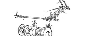
The MTZ 82 hydraulic tank is a cast iron body with one top and two side covers. A pump with a drive is attached to the lower part. The tank volume is 6 liters and is refilled with universal seasonal oils. The oil level is checked by an oil gauge using three marks: O - minimum permissible level, P - upper level, C - upper level for working with dump trailers and haystack throwers.
The general hydraulic structure is organized according to the separate-aggregate type. This means that the mounted hydraulic system and the power steering (power steering) system are controlled separately. This ensures the same ease of control regardless of the type and mode of operation of the hitch or trailer.
Working in a neutral position
In the initial position, the spools are held by springs with sufficient force, which is calculated during the factory assembly process. This is the normal inactive position of hydraulic locks. At the same time, the sleeve cups provide emphasis on the lid, located in the upper area of the structure. On the other hand, emphasis is provided on the lower part of the block. The fundamental difference between this condition is also the overlap of the verbal and discharge channels. The belts and levers of the MTZ 82 hydraulic distributor prevent oil from penetrating into the working cavities, therefore the pistons are in a fixed state. The lower channel can open when the pump is activated, which directs oil to the operating circuits.
Hydraulic system diagram
The general structure of the system includes:
- gear pump for hydraulics NSh-32-2;
- distributor Р75-33-Р;
- main cylinders Ts100 and two remote cylinders Ts75;
- power regulator providing four operating modes;
- hydraulic adhesion weight increaser (GWI), which reduces wheel slip and facilitates the operation of equipment;
- a hydraulic accumulator that serves to maintain pressure and replenish possible oil leaks;
- locking devices;
- MTZ hydraulic breakaway coupling (2 pcs);
- hydraulic tank (oil reservoir);
- oil filter;
- fastening fittings.
The pump is connected to the tank, distributor and power regulator. The suction pipe goes to the tank, and the oil discharge pipes go to the distributor and regulator. The oil flow is directed by a distributor either to the tank or to the fuel pump and then through the regulator and power cylinder it is supplied to the hydraulic drive of the trailer or attachment. As a result, the working body (blade, bucket, mower) moves in accordance with the operator’s commands.
Principle of operation
The main function of the hydraulic distributor is to direct the pump fluid into the cylinder cavity, ensuring the operation of the target attachment that is currently relevant. After the session is completed, the technical oil is transferred back to the tank as a result of automatic switching. As an additional control option, a mechanism is provided for fixing the working equipment in a certain position. But before using this function, you should take into account the pressure limitations that the MTZ 82 hydraulic distributor is, in principle, capable of withstanding. The connection diagram of the mechanism to different cylinder channels assumes separation according to purpose:
- To lower.
- For lifting.
- For regulation.
Each of the fluid supply circuits is connected to a central pipeline, a control system and a drain channel. During the control process, functional blocks with hydraulic locks are brought into an active or inactive operating position. Now it’s worth familiarizing yourself with the specific operating modes of the unit.
Possible faults
Proper operation of the system is ensured by the use of suitable parts and consumables, as well as timely maintenance. Maintenance comes down to regular oil changes, as well as checking the condition of parts, linings and oil lines.
The oil is changed once a season or after every 2000 operating hours. First start the engine until the oil warms up to 30° C. Then turn off the engine and drain the used oil through the drain hole in the bottom of the crankcase. The hydraulic oil filter is removed and washed in diesel fuel. The washed filter is put back in place and fresh oil is added until about. The recommended brand of hydraulic oil for MTZ 82 is M-8G2K, M-10G2K, M-10G2. At the final stage, start the engine and lower and raise the rear linkage mechanism several times to bleed the hydraulic system.
Maintenance memo:
- every 10 operating hours - check the oil level in the tank and make sure there are no leaks in the seals and connections of the system;
- every 60 m/h - clean the oil filter rotor;
- every 240 m/h - change the oil in the power steering;
- every 960 m/h - clean and rinse the drain filters;
- every 2000 m/h - change the oil in the power steering and wash the filters.
At the same time, the activation of the drive gear, the locking mechanism of the GSV control levers, the distributor, and power position control systems are adjusted.
The most common faults:
- wear of levers and hoses;
- incorrect adjustment;
- problems with traction;
- oil leak.
Remedies
Problem: attachments do not raise or lower.
Reason: lack of oil in the tank. Top up to the mark.
Problem: increased oil heating.
Cause: incorrect adjustment of the regulator control sector. It needs to be adjusted.
Problem: Lifting the attachment too slowly .
Cause: The hydraulic pump may be damaged, causing an oil leak. A damaged pump must be replaced.
Problem: wheel slipping when the GSV is turned on.
Reason: violation of the length of the rod of the lever controlling the main cylinder. The rod length needs to be adjusted.
Knowledge of these main faults will help you figure out if the hydraulics on the MTZ 82 do not work, what is the reason and what to do. Most problems can be fixed by yourself, but for everyone else there are forums and professional help.
What malfunctions can occur in power cylinders and how are they eliminated?
In all cases, malfunctions are eliminated by replacing worn parts.
But if increased oil leakage is detected in the pump, it is necessary to repair the pump or replace it with a new hydraulic pump. The adjustment of the sector of the regulator control mechanism is broken - Adjust the position of the sector.
In this mode, the front axle is permanently disabled. The cylinder is connected to the drain cavity. Release the cardan shaft. An increase in the pressure of the working fluid at the drain causes the working fluid to leak out through the seals of the distributor caps. Mode of forced permanent shutdown of FDA. However, this mode can only be used when moving forward; when reverse gear is engaged, the front axle is either forcibly disengaged or forcibly engaged.
Turn on the electric motor of the stand and, closing the throttle of the stand, observe the pressure gauges of the stand and the throttle-flow meter. Fill the tank to the required level and bleed the hydraulic system to remove air.
Related Posts
The front drive axle drive in general, and the hydraulic distributor in particular, do not require any special maintenance except for periodic oil changes, however, this work is carried out as part of the maintenance of the hydraulic transmission system of the tractor, and if the operating recommendations are followed, they will serve reliably for many years.
Wear or breakage of the splines of one of the levers - Replace the shaft and levers. Leakage of working fluid Along the spheres of the levers. The FDA drive operating modes are controlled by one three-position button installed on a remote control panel, next to which there is also a rear axle differential lock control button. The attachment does not rise or rises slowly when operating the distributor and rises when operating the MTZ regulator with GSV. The handle of the regulator control lever is not installed on the latch - Install the handle on the latch.
The flow area in the locking device is blocked - Tighten the union nuts of the locking devices until they are tight. The central rod is installed on the upper holes of the sensor earring - Install the central rod on the middle holes; if the depth is still insufficient, install the rod on the lower holes. Worn spools or bores in the distributor body - Replace the distributor. Why does the p 80 distributor stop working?
See also: Pd 10u
Hydraulic system of MTZ-80,82 tractors, device, hydraulic tank, spare parts - MTZ-80.RU
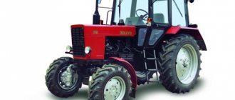
The hydraulic system is designed to provide hydraulic drive to the tractor's mounted system, as well as to provide hydraulic drive to the external power hydraulic elements of mounted and trailed machines working with the tractor. The hydraulic mounted system of universal row-crop tractors MTZ 80(82) is additionally equipped with units that automatically regulate the depth of tillage and increase the grip weight of the tractor drive wheels when working with soil-cultivating devices.
New versions of the hydraulic distributor
The mechanism does not undergo fundamental changes, but certain improvements still take place. In particular, the modification P80-3/1-222G is characterized by improved protection against leaks. The design provides more reliable seals and shut-off valve regulators. Also, the new MTZ 82 hydraulic distributor has the ability to ensure the circulation of liquids under high pressure. The operator can start, stop and fix the executive bodies in intensive mode. At the same time, the mechanics will be protected by an updated overload protection system. Like previous versions, this hydraulic distributor is universal and can be integrated into the design of tractors MTZ, YuMZ-6, DT, T-150, etc.
Essential elements
The system consists of several components that perform their functions. All of them are very important:
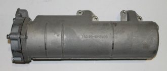
- pump. It is used to convert engine energy through a drive into the energy of a fluid flow, which moves and creates pressure. It is installed on the hydraulic unit body using studs, after which it is centered. A special glass is used for this. In MTZ tractors, PTO intermediate gears are used as a drive;
- distributor. Controls flows in the system under external influence. Performs several functions. Firstly, it transfers oil to consuming devices (cylinder, hydraulic motor, trailer). Secondly, it serves as a switch to idle mode. To do this, the liquid is redirected to the tank. Limits pressure when overload occurs.
- power hydraulic cylinders. Raise, lower or hold attachments and trailers;
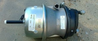
- hydraulic boosters. They regulate the adhesion weight by applying load to the drive wheels to reduce slipping;
- oil tanks. They are containers for storing oil on which other units are mounted;
- position-force regulators. Used to control agricultural machines and implements directly from the cab. Used to reduce fuel consumption and increase productivity;
- locking devices. Prevents lubricant from leaking out of the oil line;
- breakaway couplings. Used when the forces applied to the disconnecting hoses are exceeded to avoid breakages;
- connecting fittings. Pipelines connect structural elements.
You can buy spare parts for the MTZ 82 tractor and other models in the catalog of our online store.
Operation of lifting units
The function of the lifting mechanisms assumes that pressure will be provided on the spool spring from the side of the lower glass of the liner. A special bushing holds the fixed ball elements, against which the body also rises to the upper position. As the channels with the nozzle hole overlap, the hydraulic system belt rises above the oil injection line, connecting it to the cylinder. The liquid drain circuit also converges with the drain hole, that is, the mechanism is prepared for discharge into the tank. The equipment can be lifted until the cylinder of the MTZ 82 hydraulic distributor rests against the housing cover. After this, the switch to the neutral position will automatically operate. But, as a rule, the lifting process is completed by the operator himself, who stops the movement of the working parts manually from the cabin. By the way, the automatic control system is formed by a separate infrastructure, consisting of a locking screw, a ball valve, a pusher and a special spring.
Design of the MTZ-80 hydraulic system: pump diagram
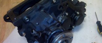
The main “pumping” mechanism of the hydraulics of an agricultural machine is a hydraulic pump. It ensures the operation of all worker nodes.
The design of a hydraulic pump is shown in this diagram.
Through the gear (11), the pump is driven by the main shaft of the tractor power rotation. The device drive is located in the upper part of the intermediate part of the MTZ-80 transmission housing near the clutch housing. The mechanism is started through the control handle (16).
Hydraulic tank design MTZ-82
The hydraulic tank of the hydraulic system of the Belarus MTZ-80(82) tractor supplies the system with working fluid and is filled with oil coming from the drain channels of the working units. Thus, the hydraulic tank closes the operating cycle of the tractor hydraulics.
The body of the tank is a metal container made of cast iron, which is located between the engine compartment and the tractor cabin. The housing also has a second function - the working components of the system are attached to it; for this purpose, the tank has a number of mounting threaded holes. The hydraulic tank structure is shown in more detail in the picture with a transcript.
Unit cost
In the segment of tractor hydraulic systems, there are not many universal solutions, so there is no need to talk about a wide choice among alternative options for MTZ 82 owners. At most, we can talk about structural modifications to the mechanism, after which it can be fully used in conjunction with working parts. But this doesn’t make much sense either, due to the operational attractiveness of the standard MTZ 82 hydraulic distributor, the price of which averages 5.5-6 thousand rubles. This is a modest cost, since similar systems for similar equipment cost 7-8 thousand. However, there may be additional costs for fittings, levers and consumables - on average, 1-2 thousand.
Hydraulic diagram MTZ-82.1
The Belarus MTZ-82.1 hydraulic attachment system includes:
- Hydraulic tank equipped with a filter.
- Hydraulic system pump - creates the required oil pressure necessary for the system to operate.
- Spool valve.
- Power hydraulic cylinders – control the raising and lowering of the attachment.
- Position-force regulator – necessary to control the position of the tractor and its attached parts.
- Drain oil line.
- Rear mounted unit.
The diagram of the MTZ-82.1 hydraulic system is presented below.
Features of the hydraulic distributor
The modification of the P80-3/1-222 hydraulic system has many differences not only from similar units that were equipped with equipment in the MTZ 50 line, but also from modern distributors found in competitive tractors. These features are mainly due to the fact that in 1998 the MTZ 82 hydraulic distributor began to be massively equipped with check valves with wide control capabilities. Today this control mechanism is known as a hydraulic lock, which increases the functionality and reliability of the system. One distributor can contain no more than four hydraulic locks (there are three of them in the standard MTZ 82 version). As a rule, a frontal arrangement is used, and in the extended configuration a lateral fourth spool is additionally introduced. All components are unified and can be interchanged with similar elements within the P80 family of hydraulic systems.