The clutch is removed from the car for repairs or when it is replaced with a new one.
To do this you need:
- remove the gearbox;
- Unscrew the bolts securing the clutch housing to the flywheel and remove the pressure disk 22 with housing 19 assembled (Fig. 33). Unscrew the fastening bolts alternately in 2-3 steps;
- unscrew the four automatic adjustment bars of the middle disk withdrawal and remove the four split rings with dampers from rod 2;
- remove the driven, middle drive 26 and first driven clutch discs.
- install the first driven disk 25 of the clutch with the elongated end of the hub towards the flywheel 24, the damper springs 30 should be on the opposite side;
- install the middle drive disk 26 with rods 2;
- install the second driven disk 25 with the elongated end of the hub towards the gearbox, the damper springs should also be located towards the gearbox;
- install the pressure plate 22 with the casing 19 assembly using eight short bolts, center both driven clutch discs relative to the axis of the crankshaft with the inserted input shaft of the gearbox and finally tighten the bolts;
- put the split rings for adjusting the release of the middle disc onto the rods until they stop at the clutch housing;
- install the thrust bars for automatically adjusting the withdrawal of the middle pressure plate and secure them with the casing to the flywheel using eight long bolts;
- After installing the clutch on the flywheel, you need to make sure that the rings on the rods rest against the housing, ensuring a gap of (1.2 ± 0.1) mm between the rings and thrust washers when the clutch is engaged.
To install the clutch you need:
After performing repair work, it is necessary to adjust the free play of the clutch pedal.
Removing and installing the release valve
Replacing the clutch on a KAMAZ 5460 ZF16 gearbox
Very tight clutch release on KamAZ 6520.
Releaser. Clutch MAZ, YaMZ 236
Replacing the clutch on KAMK
Replacing the release bearing for KamAZ 5460 gearbox ZF 16
operating principle of the Yamz diaphragm clutch release bearing clutch
installation and dismantling of the release bearing clutch Yamz
Clutch installation SCANIA R Seria Cluch Install
Adjusting the basket without removing the Kamaz gearbox and clutch nuances!
The MAZ clutch is a mechanism necessary for stable operation of the transmission. It transmits traction force to the flywheel of the YaMZ engine.
MAZ clutch repair
In the last article we wrote about what a MAZ clutch is and what components this element includes. Today we will tell you in detail how to repair a MAZ clutch. Practical advice and photos of replacing a MAZ clutch will help in repairing a modern truck.
MAZ clutch repair - where to start?
Adjusting the MAZ clutch is much more difficult than repairing the element. We will touch on the nuances of adjustment in the following articles. Now let’s study how to replace the MAZ clutch. Before you start repairing a MAZ spare part, we advise you to think about the causes of the breakdown. The MAZ clutch can fail due to the failure of the driven disk, and due to wear of the bearings, springs and seals. As a result, you may notice that the truck:
- Makes sudden jerks during winding.
- Makes noise when the pedal is pressed and a burning smell.
- Has a discrepancy between acceleration and revolution.
Another reason for MAZ clutch failure is that it is very difficult to change gears.
These wear symptoms can be eliminated by adjusting the clutch.
The very first thing we do is check the CCGT.
Press down on the clutch pedal. Pay attention to the PSU rod. If this element has a stroke, that is, it gradually squeezes out the fork with the release - the spare part is in good condition and does not require replacement. MAZ clutch repair has several stages. After checking the PSU, we look at the clutch casing. Ideally, it should not contain any oil leaks. In some cases, the clutch may “slip” due to excess oil. Let's look and eliminate the reasons. If the car, even after removing the oil and checking the PSU, is not working properly, we will repair the clutch further.
Replacing the MAZ clutch - removing the gearbox
Failure of the element in question is possible due to failure of the clutch disc, basket and bearing (release). Sometimes discs are filled with oil. However, you can understand why the clutch slips, why the clutch is tight, only after disassembling the gearbox.
Therefore, we remove the gearbox and continue repairing the MAZ clutch. I recommend replacing several MAZ spare parts along the way, which, in principle, do not affect clutch failure.
The fact is that in most cases the elements have significant signs of wear, which will lead to breakdown over time. Moreover, if you are repairing a MAZ clutch, it means that the box has not been removed for at least a year.
Therefore, some consumables will actually have to be replaced. Replacing a MAZ clutch most often includes purchasing a new one:
- Clutch disc.
- Release bearing hose.
- Release bearing.
- Gearbox input shaft oil seal.
- Bearing spring.
- Gaskets for oil pump and shaft.
Only after purchasing new parts do I recommend repairing the MAZ clutch.
Replacement of dump truck clutch
First, we raise the body. Don't forget to lock it in this position.
So replacing the MAZ clutch will not harm you. In general, follow basic safety precautions. Then gradually drain the oil from the gearbox. We disconnect such elements as the body lift pump, cardan and tubes.
Repairing the MAZ clutch also requires removing the yoke with the rear support pad, the PGU and its bracket.
Let me emphasize - ALWAYS remove the bracket! Adjusting the MAZ clutch, most often, if the bracket is not removed, can lead to breakage of the release bearing fork and its spring.
After this, inspect the condition of the release bearing and gearbox basket. If you do not find any signs of wear on these elements, adjust the clutch further. Therefore, we remove the basket from the car flywheel. This will give us access to the clutch disc. Let's examine the detail. If we find traces of damage, we repair it or replace the part with a new one. If the disc is in good condition, then replacing the clutch continues.
Adjusting the MAZ clutch may seem like a simple task, but... there are a lot of nuances here. For example, the support bearing of the input shaft. Let me remind you that it is located in the flywheel. With long-term operation of a MAZ dump truck, this element wears out very much. It all starts with the oil seal. As soon as you replace it, the spare part may still leak oil. Therefore, if you need to replace the clutch, change the bearing too - issues with the oil seal will disappear for a couple of years, just as long as you replace the element in time.
Clutch replacement tips
We recommend that you do such a process as adjusting the clutch in a certain sequence.
Look at the clutch disc first. If it is faulty, replace it with a new one. In this case, pay attention to the support bearing. If the element does not require replacement, simply lubricate it with oil and install it.
Carefully inspect the clutch basket. Adjusting the MAZ clutch requires careful checking of the integrity of the clutch petals, the presence of signs of overheating and cracks. Inspect the release bearing. It is best to replace this part immediately. Otherwise, the MAZ clutch adjustment will be repeated at least twice.
The MAZ clutch adjustment is complete. After completing the process, we install the clutch and gearbox on the dump truck. Naturally, we do the assembly in reverse order. But we will clarify some nuances in the assembly of this element.
Adjusting the MAZ clutch requires removing the clutch disc. However, installing it can present several difficulties. So it is necessary to use the input shaft for alignment relative to the bearing and disc basket.
Also, replacing the MAZ clutch, or rather installing the element, can also be done using a plastic input shaft. As a rule, it is cheaper and lighter. Otherwise, replacing the MAZ clutch and assembling the element usually does not cause difficulties.
Inspect your truck as often as possible. If you identify the causes of breakdowns, urgently repair the MAZ clutch. So this element will rarely bother you.
Subscribe to our channels on social networks, , in contact, .
Engines SMD and D-245 on MAZ 4370 Zubrenok
The SMD and D-245 engines on the MAZ Zubrenok are the main ones of all power units. Moreover, the D-245 motor is the leading one and is installed on three out of four models. This is an archaic, but reliable and time-tested motor. It doesn't cause problems and its power (155 horsepower) is enough for driving on public roads. At this point in time, the MAZ Zubrenok is the most common medium-duty truck in Belarus. Today, a Manov engine is being installed.
How to install a release bearing on a MAZ - Special equipment
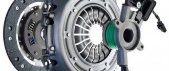
A clutch is one of the components of a car’s transmission, which serves to temporarily disconnect the gearbox from the engine, as well as smoothly engage it.
It is a basket in which the main parts are assembled - the driven and pressure plate, fork, release bearing and leaf spring. With proper operation, you only need to change the driven disk and lubricate some elements.
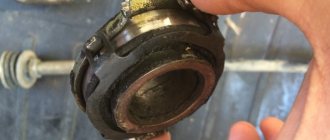
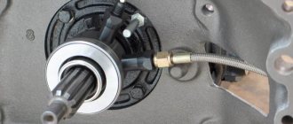
Their list also includes a release bearing. It needs lubrication periodically, and this can be determined by the noise when you press the clutch pedal.
How does a release bearing work?
The release bearing is mounted on the input shaft of the gearbox and has splines on the inside that prevent it from turning. The essence of the work is this: the driver uses the pedal to create pressure in the main cylinder, which transmits it to the working piston. A rod is attached to it, and a fork is attached to the rod.
It rests on special places in the release bearing (antennae), thereby pushing it along the input shaft to the leaf spring. Having rested against it, it begins to work, that is, to spin. Simply put, the device is active only when the clutch pedal is depressed, when it comes into contact with the spring.
Engines for MAZ 4370
The MAZ 4370 cargo Zubrenok was produced in four modifications, which differed in power plants. Initially, the Belarusian MMZ D-245 engine was installed on the truck. The engine did not meet European environmental standards, so it needed improvement. Quite quickly it was replaced with an improved version D-245.30, which already complied with the Euro-2 standard. A few years later, the engine was further refined to the Euro-3 standard. In addition to Minsk engines, the MAZ 4370 was equipped with the German Deutz BF4M 1013FC engine, which meets Euro-3. But the latest modifications can be found relatively rarely in Russia.
Engine MAZ 4370 D-245
Diesel engine D-245 on the MAZ 4370
The main engine for the MAZ 4370 was the Belarusian D-245. This is a turbocharged diesel engine, which has appeared on many models of tractors and special equipment and has proven itself in both operation and maintenance. The 4.75-liter engine has 1.5 thousand revolutions per minute and generates 157 hp. This allows it to be high-torque on the one hand, and on the other hand have good fuel efficiency: in the combined cycle, consumption per “hundred” reaches 17 liters.
By design, the MAZ 4370 D-245 engine is 4-stroke, has four cylinders arranged in one row.
Table of technical characteristics of MAZ 4370 D-245 Euro3
| Working volume | 4.75 liters |
| Power | 95 kW or 157 hp |
| Nominal speed | 1.5 thousand rpm |
| Max. torque | 580 N*m |
| Diesel fuel compression ratio | 17 |
| Fuel consumption | 17 l/100 km (combined cycle) |
| Weight | 0.45 t |
Engine MAZ 4370 Deutz BF4M 1013FC
Diesel engine Deutz BF4M 1013FC, which was installed on the MAZ-4370
An alternative propulsion system was the Deutz BF4M 1013FC - a four-stroke diesel engine with four cylinders, liquid-cooled, a turbocharger and direct fuel injection. The valves are located on top. Starter 12V/24V. If we compare the Deutz BF4M 1013FC with the D-245, then the technical characteristics are approximately the same. But Zubrenok with Deutz BF4M 1013FC works much quieter.
Table of technical characteristics of MAZ 4370 Deutz BF4M 1013FC Euro3
| Working volume | 4.76 liters |
| Power | 129 kW or 173 hp |
| Nominal speed | 1.5 thousand rpm |
| Max. torque | 700 N*m |
| Diesel fuel compression ratio | 17,5 |
| Fuel consumption at 100% load | 29 l/h |
| Weight | 0.432 t |
Clutch T-150/T-150K: diagram, principle of operation, adjustment
The clutch on the T-150 and T-150K tractors is responsible for smooth starting. The serviceability of the module and its correct adjustment play an important role in this. How the clutch on the wheeled and tracked T-150 works, what parts it consists of, how to replace spare parts and make adjustments - we will answer these and other questions in this article.
The role of clutch on T-150 and T-150K
The clutch is one of the key elements of the transmission. It takes on most of the energy when selecting speeds and protects the tractor from overloads by damping vibrations.
The operating principle of this module on the T-150 and T-150K tractors is no different from the mechanics of its functioning on passenger cars. It disconnects the motor from the transmission and also connects them when it is necessary to change gears. The need to install a clutch is due to the fact that the engine runs continuously, but the wheels do not. If the T-150 didn't have a clutch, you'd have to turn off the engine every time the tractor stopped. When starting, this unit again combines the rotating engine and the static box, carefully connecting the shafts to each other. Due to this, the tractor moves off smoothly.
Clutches T-150 and T-150K: what they have in common and how they differ
The clutch design on the tracked T-150 and the wheeled T-150K is as similar as possible, but there are still differences - in the details of the drive mechanism. The clutch housing of a crawler tractor is indirectly connected to the transmission housing. For the wheeled modification, a spacer housing is mounted between them. Because of this difference in installation, the T-150K clutch shaft is longer than the T-150.
Another difference in the design of the clutches of wheeled and tracked tractors lies in the servo mechanism, which is installed to reduce the energy expended to disengage the clutch. Depending on the modification, the amplifier is mounted:
- on pneumatics (on the wheeled version);
- on mechanics (on the version with tracks).
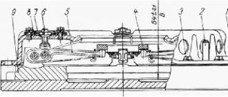
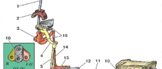
Diagram of the mechanical servomechanism of the T-150 clutch
The clutch release drive is shown schematically in this figure. The numbers indicate the following details:
- pedal;
- double arm lever;
- earring;
- craving;
- spring element;
- conn. craving;
- support part;
- release housing bearing;
- nut for adjustment;
- stopper;
- spring stop bolt;
- fork;
- ring of levers for spinning;
- thrust element;
- lever arm.
The spring of the mechanical servomechanism, when the clutch of the T-150 tractor is engaged, moves the pedal as far back as possible. The foot pedal is held by pressing the amplifier earring on the smaller protrusion of the two-arm lever. When the pedal is pressed, the spring stretches. After this, the spring is compressed, which leads to rotation of the two-arm lever. The consequence of this is that the clutch of the tracked T-150 is disconnected.
Diagram of the pneumatic servomechanism of the T-150K clutch
The following digital symbols are marked on the wheel tractor clutch release drive diagram:
- pedal;
- lever arm;
- linkage;
- tracking device;
- drain hose;
- release bearing;
- nut for adjustment;
- spring stop;
- spring stop bolt;
- fork;
- release stop bearing;
- ring of release levers;
- lever arm;
- supply hose
The housing of the tracking device of the pneumatic servomechanism of the clutch of the T-150K tractor is connected to the rod. There is a pneumatic chamber located on the coupling body, which is connected to a tracking device using pipelines.
Clutch basket for T-150/T-150K tractors
When the pedal is depressed, the plunger moves along its axis, opening the valve. Through the resulting hole, air under pressure enters the air-compression chamber. This leads to movement of the chamber rod, which in turn stops the T-150K clutch. If you release the pedal, the plunger stops pressing on the valve, and it closes the hole, moving to its original position.
Features of the clutch design on different modifications of the T-150/T-150K
Over the years of production of tracked and wheeled tractors, many different modifications have been produced. And for different variations of special equipment, excellent clutch options were offered.
Most T-150 series tractors were equipped with dry-type friction double-disc clutches that were permanently closed. But you can also find a single-plate clutch. Initially, the discs were made from alloys with a high asbestos content, but in recent years the composition of the material has changed.
Types of clutches and parts with catalog numbers for T-150/T-150K with SMD-60, YaMZ-236, YaMZ-238, Deutz, MAZ engines
To make it easier to navigate the variety of parts and their purposes, we offer the following table.
| Part number | Part name | Which engine are they suitable for? | Peculiarities |
| 151.21.021-3 | Clutch body | installed with SMD-60 motor | |
| 150.21.022-2A | Basket | ||
| 150.21.222 | Squeeze glass bearing | ||
| 01M-2126 | Including plug | suitable for Deutz engine | |
| 01M-21C9 | Clutch off | ||
| 151.21.034-3 | Clutch shaft | suitable not only for SMD engine, but also for YaMZ | |
| 150.21.0243A | Driven disk with linings | ||
| 172.21.021 | Clutch housing | spare parts are supplied with the YaMZ-236 engine, double-disc clutch | it also fits the Deutz engine |
| 236T-150-1601090 | Basket | for two disks | |
| 150.21.222 | Squeeze glass bearing | the same as for the T-150 clutch with SMD-60 | |
| 01M-21 S9 | Clutch off | ||
| 151.21.034-3 | coupling shaft | ||
| 150.21.024-3A | Driven disk (thickness 17) with linings | ||
| 172.21041 | Clutch body | YaMZ-236, single-disc petal clutch | |
| 181.1601090 | Petal clutch basket | for one disk | |
| 171.21.222 | Release bearing cup | ||
| 172.21121 | Power plug | ||
| 172.21.032/034 | Clutch in clutch release assembly/shaft | ||
| 172.21.024 | Driven disk with linings (thickness 24) |
Set of parts for replacing clutch T-150 with SMD-60
Set of parts for replacing the T-150 clutch with YaMZ-236
To replace parts on the clutch of a T-150 tractor with a Deutz engine, a basket with a disk and a bearing is assembled, which is very convenient. But if necessary, spare parts can be found separately.
Maintenance of tractor clutch T-150/T-150K
Taking into account the specifics of the operation of special equipment, the frequency of maintenance for it is determined not by mileage or time, as with passenger cars and commercial vehicles, but by engine hours. According to safety standards, maintenance periods cannot be exceeded by more than 10%. Also, sometimes service intervals are determined by fuel consumption, but if the engine is incorrectly adjusted, these parameters can distort the picture.
For tractors T-150 and T-150K, the following types of maintenance are determined:
- ETO - carried out after each work shift on the tractor;
- TO-1 - at intervals of 125 engine hours;
- TO-2 - with an interval of 500 engine hours (for older models the resource is 240 hours);
- TO-3 - at intervals of 1000 engine hours.
Seasonal maintenance is also provided, which is carried out twice a year in preparation of the T-150 for the change of season.
Checking clutch operation on T-150/T-150K
Checking the general technical condition, flushing and changing the oil in the clutch of T-150 tractors is carried out as part of the third maintenance. To do this, start the engine, engage the gear and select the average crankshaft speed. The tractor, which is moving along a flat area, is braked, while the clutch remains engaged. During normal operation of the unit, the engine should stop. If it slows down but does not stop, the clutch discs slip.
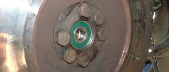
Clutch disc T-150K with signs of wear
The next step is to visually check the clutch. To do this, stop the tractor and turn off the engine. If, when opening the hatch, smoke is visible, strong heating of the body is felt, a characteristic odor is present, etc. - this also indicates disk slippage.
Flushing the clutch discs can correct the situation. To do this, the unit is stopped and the crankshaft is cranked manually. During the process, the discs are washed with kerosene or gasoline. After the technical fluids have completely drained, you need to check the T-150 clutch discs again for slipping. If washing does not help get rid of the problem, you may need to replace the friction linings.
New clutch discs for the T-150 tractor
How to adjust the clutch on a T-150/T-150K
The clutch on the T-150 and T-150K tractors needs precise adjustment, because even with small deviations the system will not function correctly. Let's look at how to adjust the clutch using examples of common faults.
In order for the clutch to operate correctly, there must be a gap of 0.4 cm between the release bearing and the ring of the release levers in the disengaged state. The more the disc linings wear out, the smaller the gap becomes. Over time, it may disappear completely, leading to slipping or complete clutch failure.
An excessively large distance also negatively affects the functioning of the T-150 tractor transmission. There may be problems with changing gears and starting the car. This also increases wear on the friction linings. Therefore, the main manipulation when adjusting the T-150 clutch is setting the correct distance for the gap. The main steps are as follows:
- loosen the return nuts;
- screw in or unscrew the rod (to increase/decrease the gap, respectively);
- tighten the locknuts;
- measure the distance.
If, by changing the position of the rod, it is not possible to set the required gap, it is corrected by adjusting the position of the clutch basket release levers. To do this, perform the following steps:
- open the hatch and remove the cover;
- rotate the crankshaft, loosening the nuts one by one to adjust;
- change the rod length to achieve the desired clearance;
- turn on the clutch and evaluate the correctness of the adjustment;
- tighten the adjusting nuts.
The T-150 brake may also need adjustment.
Read the most interesting things about special equipment in the “Special Equipment News” section!
Brake system MAZ 4370
In the MAZ 4370, the braking system is implemented independently for the front and rear axles. It is pneumatic and consists of the following components:
- compressor;
- receivers (compressed air cylinders);
- pneumatic drives;
- control devices;
- braking mechanisms.
On regular cog trucks the compressor is single cylinder. Modifications of the MAZ 4370 for road trains were equipped with a two-cylinder compressor.
Brake drum from MAZ-4370
The direct element of the braking system are drum brakes. The drum is cast from cast iron, its diameter is 420 mm, and its thickness is 160 mm.
MAZ 4370 pads are made of steel. Overlays are installed on top of them. To adjust the distance between the drum and the pads, there is a corresponding lever.
Brake system MAZ-4370 (drum with pads)
On the one hand, the configuration of the MAZ 4370 Zubrenok brake system is flexible, on the other hand, it requires precise adjustment for each axle and individual wheel. Otherwise, skidding may occur or the braking distance may increase.
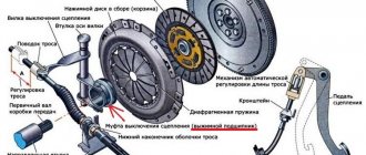
Yamz release single-disc installation
The MAZ clutch is a mechanism necessary for stable operation of the transmission. It transmits traction force to the flywheel of the YaMZ engine.
Design and principles of operation
The design of the coupling mechanism includes such elements as:
- flywheel;
- hydraulic power steering;
- overlays;
- a spring device that presses the disk against the flywheel housing;
- clutch release fork, clutch release drive;
- push-type coupling;
- coupling pedal shaft;
- pressure disk;
- double-disc or single-disc petal device;
- release bearing;
- protective casing;
- transmission drive shaft.
- When the driver presses the pedal, the shaft begins to rotate.
- A gap forms between the fork and the push-type coupling.
- The clutch, together with the bearing, begins to move, causing the bearing to exert pressure on the inner ring of the handle.
- The handle moves the pressure plate away from the driven disc.
- The spring mechanism is compressed, causing the disk to move towards the flywheel of the power unit.
- The splines of the driven disk move to the splines of the gearbox input shaft.
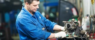
How the repair is carried out
Main malfunctions and ways to eliminate them:
- The clutch mechanism is slipping. This may be due to the lack of free play of the pedal, jamming of the piston part, wear of the friction linings. In this case, it is recommended to adjust the free play of the pedal, clean all cylindrical elements and valves with kerosene, and replace damaged linings and cylinders.
- The clutch moves or does not disengage completely. Such a malfunction can be caused by an incorrectly adjusted length of the cylinder rod, insufficient air pressure in the pneumatic system, a leak in the piston seal, or failure of the pull-out levers. The rod length should be re-adjusted, the pneumatic system should be inspected and, if necessary, leaks should be eliminated, the cylinders should be flushed, and all damaged and worn parts should be replaced.
- The pedal does not return to its original position. It is recommended to adjust the gap between the back cover and the lock ring, replace worn valves, move the spring mechanism holder closer to the rod, eliminate defects in the rods, clean and lubricate the cylindrical elements of the system.
How to replace
Replacing the clutch is carried out in several stages:
How to remove
In order to dismantle the coupling mechanism, you must perform the following steps:
- Place the vehicle on a special platform or inspection hole.
- Remove the battery.
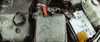
- Remove the air filter element.
- Remove the engine splash guards, which are located in the lower and side parts of the power unit compartment.
- Remove the front suspension cross member.
- Remove the front drive wheels.
- Drain the oil fluid.
- Disconnect the speed sensor using a screwdriver.
- Remove the reverse switch.
- Remove the engine harness holder.
- Unscrew the mounting bolts and remove the starter housing.
- Disconnect the engine mounts from the gearbox bracket.
- Move the clutch back.
- Remove the input shaft of the mechanism.
- Unscrew the mounting bolts from the coupling mechanism housing. The bolts are unscrewed one by one, in 2-3 steps.
- Remove the pressure plate along with the casing.
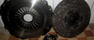
Assembly
Clutch mechanism assembly steps:
- Assemble the driven disk. To do this, it is necessary to attach friction linings to a plastic spring device.
- Assemble the pressure plate. You need to lubricate the rollers with a special liquid, place them in the hole of the pull handles, insert the lever into the groove that is located on the pressure-type disk, and install the finger. Attach the support forks to the levers and secure them with cotter pins.
- Assemble the pressure disk with the casing. This must be done under a press that can compress the springs and screw the bolts into the support forks. A driven type disk is placed under the press, and a pressure disk is placed on top. Heat-insulating washers and the spring mechanisms themselves are installed on special protrusions. Press the casing using a press and tighten the mounting bolts.
- Installing discs into the clutch housing.
Procedure for installing the clutch:
- Install the driven disc so that the extended end of the hub faces the flywheel.
- Install the drive disk element with rods.
- Install a second driven disk with the elongated end of the hub pointing towards the gearbox.
- Install the pressure plate.
- Attach the cut adjusting rings to the structure.
- Install the stop bars and secure them with the casing.
- Install the clutch mechanism on the flywheel, check the gap between the thrust rings and washers by engaging the clutch mechanism.
Service
Maintenance of this mechanism is carried out as follows:
- Carry out an external inspection of the pedal and, if necessary, adjust its free play.
- Bleed the hydraulic drive.
- Carry out diagnostics of the crankcase fastening elements and, if necessary, tighten the nuts.
- Carry out an external inspection of the tension spring device, lubricate the bearings and hydraulic coupling.
- Check the functionality of the clutch switch and the shaft sleeve.
- Inspect the fork and clutch pedal for wear and damage.
- Check the operation of the mechanism by changing the gears of the vehicle on the spot and during acceleration.
- Eliminate incorrectly set gaps between support rings and washers.
- Eliminate leaks in the system and lubricate all cylindrical elements with a special liquid.
- Check the gap between the rods and the piston part of the main cylindrical device.
Leaf gas dynamic bearings
Gas-dynamic petal bearings are oil-free bearings that completely eliminate the use of oil in turbines and engines and increase the power density of aircraft turbines and engines, making them smaller, faster, hotter. As a result, they use less fuel to lift a larger load (passengers or heavier cargo).
Description:
Gas-dynamic petal bearings are oil-free bearings that completely eliminate the use of oil in turbines and engines and increase the power density of aircraft turbines and engines, making them smaller, faster, hotter. As a result, they use less fuel to lift a larger load (passengers or heavier cargo).
Gas-dynamic petal bearings completely relieve engines and turbines of the lubrication system, reduce engine weight and at the same time reduce the effort required for engine maintenance.
For reference. Airplane and helicopter turbo engines are currently lubricated with oil. But oil catastrophically loses its properties at high operating temperatures, at which turbines operate most efficiently. In addition, one rule of thumb suggests that up to a quarter of the turbine's weight consists of lubrication pumps, filters, and oil lines.
Leaf gas-dynamic bearings have a relatively simple design and operating principle. The bearing surface of the bearing is formed by thin elastic metal plates. A low-friction anti-friction coating is applied to the surface of the plates, which “lubricates” the bearing at start-up until the shaft can rotate fast enough to create a wedge of air between it and the bearing.
As the rotor speed increases, the gas layer completely separates the working surfaces of the rotor and bearing. An increase in speed is accompanied by an increase in the bearing's load-bearing capacity. Basically, the shaft floats on a film of air, similar to an air hockey puck. The only difference is that there is no need to pump air to the support itself.
The rotation of the shaft is provided by its own compressed air.
Gas dynamic petal bearings change shape depending on the conditions in which they operate to create optimal clearance geometry.
Leaf gas-dynamic bearings have unique stabilizing properties. They prevent the occurrence of vortex instability of the rotor and operate with limited imbalance.
Currently, two main types of gas-dynamic petal bearings are known: bearings with backing corrugated elements and one load-bearing petal (bump type) and bearings with mutually overlapping petals (leaf type). Bump type bearings have a greater load-bearing capacity, and leaf type bearings have a greater damping capacity, so the first type is used in stationary machines, and the second type is used in transport machines.
Advantages:
– autonomy of operation (no renewable lubrication and no need to supply air or other working gas under pressure into the working clearances of the bearing),
– effective damping of rotor vibrations due to the dissipation of vibrational energy in numerous friction zones inside the bearing,
– the ability to simplify the requirements for the accuracy of manufacturing parts and assembly due to the presence of sufficiently large clearances inside the bearing,
– reduced requirements for the purity of working air (or other gas),
– reduced requirements for rotor balancing accuracy,
– great resource. The predicted service life of turbomachines with gas-dynamic petal bearings is approaching 300 thousand hours,
– allows to significantly reduce the number of failures of high-speed turbomachines,
– high degree of environmental cleanliness (no oil),
– high reliability, heat resistance.
Application:
– engines,
– turbojet engines,
– turbomachines,
– electric cars,
– high-speed turbogenerators.
Site Map
release bearing on the UAZ petal basket hydrodynamic petal bearing replacing the MAZ release bearing single-disc petal petal clutch need release bearing clearance flap bearings gas petal bearing release bearing MAZ single-disc petal assembly of the release bearing on the Yamz petal basket installation of the MAZ release bearing single-disc lep Installation of release bearing MAZ single-disc petal 184 installation of the release bearing MAZ single-disc petal video
Electrical diagram MAZ 4370 Zubrenok
MAZ-4370 electrical diagram, color
The electrical engine control system is equipped with a built-in self-diagnostic function and does not require maintenance, except for a control check after repair or adjustment of elements and components of the fuel system.
Layout of electronic control systems on the MAZ 4370
Scheme of electronic control systems MAZ-4370
To install electrical equipment on the MAZ 4370, you can use the following electrical diagram.
Installation diagram of electrical equipment MAZ-4370
The relay and fuse panel on the MAZ 4370 looks like this:
Relays and fuses in the MAZ-4370 cab
Chassis and suspension
The chassis and suspension of the MAZ 4370 deserve praise. It is largely due to the excellent quality of Zubrenok’s design and suspension assembly that it has become so widely used. With careful operation without major repairs, the chassis will last 250 thousand km, but even then, after replacing worn out elements, it will work for hundreds of thousands of kilometers without any problems.
The front spring of the MAZ 4370 consists of several sheets. The front suspension is equipped with hydraulic shock absorbers with stabilizers. The rear spring is semi-elliptical.
In general, this design gives a rough ride, but is easy and simple to repair and does not require special maintenance.
Wheel sizes range from 17 to 20”. The suitable tire size is 235/75R17.5.
History of creation
The MAZ-4370 gearbox is one of the first modifications of the truck.
The Minsk Automobile Plant developed the concept of the future MAZ 4370 in cooperation with the Gorky Automobile Plant. The first conceptual low-frame, medium-tonnage trucks were designed by enterprise engineers in the 90s. But after the collapse of the USSR, MAZ decided to refuse cooperation with the Russian automobile plant, since for a number of reasons it became difficult to interact with representatives of another state. In this regard, Minsk decided to stop supplies for other trucks, in particular for MAZ 5336, cabs produced by GAZ.
Without abandoning the idea of creating a medium-tonnage truck, Mazov engineers decided to take the MAN L 2000, assembled in Germany, as a prototype. Having adjusted a number of functions and increased the carrying capacity, the Minsk Automobile Plant created the MAZ 4370 Zubrenok exactly in the form in which it rolled off the assembly line in 1999.
Entering the Russian market
At the time the new product appeared on the Russian truck market, there were two main competitors in this class - GAZ 3310 and ZIL 5301. The Belarusian medium-duty truck outperformed them in several ways. Firstly, the cabin was more spacious and comfortable. Secondly, the carrying capacity of the new product was higher, which was perhaps the most powerful argument in its favor, all other things being equal. For a long time, the MAZ 4370 truck simply had no competitors in the domestic car market. Zubrenok is in high demand to this day.
In 2007, the Kama Automobile Plant launched onto the market a direct competitor to the Zubrenok MAZ 4370 - KamAZ 4308, which was popularly nicknamed “Kamazenok”. Not wanting to give up their position, the automaker worked on modernizing their truck. In 2010, the manufacturer introduced the second generation of Zubrenok. The updated truck received the MAZ 4371 index. It has a redesigned cabin, which has become even more comfortable to meet the requirements of the time. Also, the MAZ 4371 Zubrenok-2 was equipped with more environmentally friendly diesel engines.
Previously, we wrote about the technical characteristics of the KS-5473 Dnepr truck crane and the features of its operation.
Source