UAZ Hunter (UAZ-315195)
, colloquially known as "UAZ", was produced in 2003, 2004, 2005, 2006, 2007, 2008, 2009, 2010, 2011, 2013, 2014, 2015, 2016, 2017, 2022, 2022 both with gasoline (injector and carburetor ZMZ -
409 ), as well as with diesel engines ZMZ-5143 in various modifications (UAZ-31512, UAZ-31514) and represents an updated version of the UAZ-469 and UAZ-3151 models that have been produced since 1972. In this publication you will find a description of the fuse and relay blocks of the UAZ Hunter 469 with diagrams and their locations. Note the fuse responsible for the cigarette lighter. In conclusion, we suggest that you familiarize yourself with the complete electrical diagram and the original operating instructions.
The design of the blocks and the purpose of the elements in them in your UAZ Hunter may differ from that presented and depend on the year of manufacture and the level of equipment.
Main starter relay
The car's electric starting system includes, in addition to the starter and relay, also starter on/off elements, various connecting wires, the main power source (battery), etc.
The starter relay or VR is activated after turning the key in the ignition switch. The BP armature and the freewheel lever move, and the bendix engages with the flywheel crown. This ensures normal engine starting.
To be able to adjust the system, you need to disconnect the current wiring from the VR. The control terminal is marked on the terminal with the letter M.
Then the battery is removed from its original place and connected to the M and S terminals marked on the terminals. Thus, the purpose of the operation performed is to shift the bendix. And in order to connect the BP to the starter, you must first adjust the gap between the bendix and the stop. It is also recommended to adjust the gasket located between the drive and the BP.
Prevention measures
What preventative measures will help protect your car’s electrical network from malfunctions:
- When the engine is off, limit the use of electrical equipment, as the battery will drain faster;
- From time to time, diagnose the performance of the battery and check its charge;
- ensure reliable insulation of the wiring;
- never use homemade fuses.
The main command vehicle of the armed forces - this is how the UAZ 469 SUV can be described. And indeed, having replaced the GAZ-69 in 1972, it secured this honorable duty for many years, proving the correctness of the design and main components with its endurance and reliability.
Additional VR starter
On modern cars, an additional VR starter is a priori provided. On older cars, the relay is installed and connected independently.
The advantages of installing an additional VR are obvious:
- Protects the starter device from burnout of contacts in the lock, which occurs for various reasons (long start-up, banal wear, etc.);
- It has a positive effect on the loading of contacts of the same ignition switch, as a result of which the contacts remain operational longer;
- Protection of the starter from a situation where, due to a “glitch” of the key in the ignition switch (the engine has started, but the starter continues to spin).
You can check whether the additional VR is installed on the car like this:
- Look in the “black box” (fuse box);
- Turn on the starter device in the engine purging mode - if the additional relay is on, then the starter must turn off on its own after a few seconds.
Connection of additional VR
Here's how to connect:
- Fix the relay in any convenient place (you can on the stud of the glass cleaning fluid reservoir);
- Connect the cable to the starter;
- Remove the red wire from the flat terminal of the main relay, and in its place insert the wire from the additional VR;
- Connect the other wire of the new BP with an 8 mm tip to the positive of the starter;
- Place contact 30 of the additional VR onto the released contact of the main VR;
- Screw the short wire numbered 85 to the body (ground).
Additional relays can be purchased in stores. They are sold as a kit, where everything is provided for proper self-installation.
Forget about fines from cameras! An absolutely legal new product - NANOFILM, which hides your license plates from IR cameras (which are installed in all cities). More details at the link.
- Absolutely legal (Article 12.2.4).
- Hides from photo and video recording.
- Installs independently in 2 minutes.
- Invisible to the human eye, does not deteriorate due to weather.
- 2 year warranty
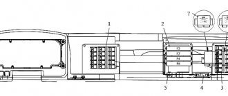
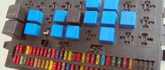
Blocks in the cabin
Fuse box
It is located under the panel, slightly above the steering rack.
Photo - diagram
Description
| 1 | 25A Reserve |
| 2 | 5A Side light right side |
| 3 | 7.5A Low beam right side |
| 4 | 10A High beam right side |
| 5 | 7.5A Fog lamp right |
| 6 | 5A Fuse Box Lighting, Portable Lamp Socket |
| 7 | 7.5A Brake lights |
| 8 | 10A Direction indicators in hazard warning mode |
| 9 | 20A Horn |
| 10 | 7.5A License plate lights, instrument lighting, switches |
| 11 | 15A Cigarette lighter |
| 12 | 5A Rear fog lamp |
| 13 | 10A Radio equipment |
| 14 | 25A Reserve |
| 15 | 5A Side light left side |
| 16 | 7.5A Low beam left side |
| 17 | 10A High beam left side |
| 18 | 7.5A Fog lamp |
| 19 | 5A Left reversing light |
| 20 | 7.5A Turn signals in turn signal mode |
| 21 | 10A Heater |
| 22 | 20A Wiper motor, windshield washer |
| 23 | 7.5A Lighting lamps, engine compartment lamp |
| 24 | 15A Reserve |
| 25 | 5A Devices and signaling devices |
| 26 | 10A Additional pump for heating system UAZ 315148 |
Fuse number 11 at 15A is responsible for the cigarette lighter.
Relay block
It is located under the panel, near the left drain.
Scheme
Designation
- low beam headlight relay
- headlight high beam relay
- fog light relay
- tailgate wiper relay
- rear fog light relay
- windshield wiper relay
- turn signal relay
Starter relay description purpose device repair photo video
Share “Starter relay description purpose device repair photo video”
The movement of any car begins with starting the engine . If you want to understand the principles of operation of the main components of a car, we recommend starting your study with the starting system. One of the most vulnerable points of this system is the starter relay. Almost everyone has heard about this detail, but not many understand the principle of its operation. Before we start talking about the starter relay, it is worth noting that the design of the car simultaneously has two parts with the same name, only the first is responsible for turning on the starter, it is usually located in the engine compartment, and the second is the starter solenoid relay.
Replacing the ignition switch and relay
Disconnect the battery using the ground switch.
Using a slotted screwdriver, unscrew the four screws connecting the steering column casings.
Using a Phillips screwdriver, unscrew the self-tapping screw securing the lower part of the casing.
In its lower part there is a wiring harness block with a connected ignition relay.
...disconnect it from the wiring harness block and install a new one.
To remove the ignition switch...
...disconnect the ignition switch wiring harness block and...
...two ignition relay connectors.
Using a wrench or a 10mm socket, unscrew two special bolts (with breakable heads) securing the ignition switch to the steering column.
If the bolt heads are broken, you can remove the bolts using a small, sharp chisel.
Remove the switch from the steering column.
To replace the contact group...
...with a thin beard we knock out two locking pins.
Using a Phillips screwdriver, unscrew the screw securing the cover...
We remove the contact group.
We install a new contact group so that...
...the protrusion on the lock cylinder fits into the groove of the contact group.
... use a hammer to hammer the pins into the holes.
We perform further assembly and installation of the ignition switch in the reverse order. You can break off the heads of the switch mounting bolts to ensure the anti-theft properties of the lock.
USEFUL TIPS
Repair of the current carrying plate runner
When repairing a worn runner in the ignition distributor by soldering a brass strip onto a current-carrying plate, it is difficult to determine the required size from the axis of the runner to its edge. If the strip is shorter, we will not get the effect of the repair, and if it is longer, the plate will touch the terminals of the cover. To determine this size, before repairing, place a piece of plasticine on the end of the current difference plate and, having installed the distributor cap, rotate the crankshaft. Excess plasticine is cut off with the leads, after which we measure size “a”. Having soldered a strip of brass, we process its protruding end to a size 0.1 mm smaller than the “a” value.
1 – additional plate; 2 – standard current carrying plate; 3 – runner body
Glue the cover of the breaker-distributor
If the cover of the breaker-distributor cracks along the way, and there is no spare (or suitable glue), you can glue it together... with garlic juice. Rub the broken area with a clove of garlic and squeeze the parts of the lid for one to two minutes, as if using regular glue. Garlic “glue” is not afraid of elevated temperatures in the engine compartment and has good electrical insulating properties. You can drive with such a cover for quite a long time - with good quality of gluing, up to several hundred km.
Source
WHAT IS A STARTER RELAY
So, let's start with the basics. Two relays are responsible for the starter. The first is installed in the engine compartment. The design can have its own housing or be installed in a common unit.
In this article, we will be much more interested in the second relay, which is responsible for the operation of the starter, namely the retractor. It performs the following functions:
- redistributes energy between the starter and the electromagnetic relay;
- feeds Bendix gears;
- synchronizes the starter components,
- returns the gears to their original position after you turn off the engine.
In the automotive world, this unit has two names: traction and retraction. The first is most often used in specialized literature, the second is popular.
To understand why a starter solenoid relay is needed, let’s look at the engine’s operation schematically. To start the engine, the crankshaft must begin to rotate. Only after this does the fuel-air mixture ignite in the combustion chamber.
Usually the engine starting process takes place within a second. The role of the relay in it is quite simple. Thanks to it, the gear elements engage with each other. It synchronizes the operation of the starter. This unit also removes the bendix from the flywheel.
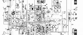
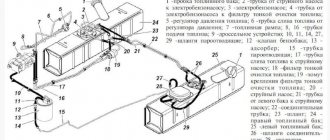
Wiring diagram for injection UAZ loaf
One of the most common problems with domestic cars is the breakdown of any electrical devices; an electrical diagram will help you figure this out. The only solution to this problem will be to check the condition of the fuses. The topic of today's article will be the electrical circuit of a UAZ Bukhanka car on an injector-type engine.
So, this article provides answers to these fairly common questions:
- What is the electrical circuit on a UAZ Bukhanka car with an injector type engine?
- How does the electrical circuit of the UAZ Bukhanka car work?
- Where are the fuses located on a UAZ Bukhanka car with an injector type engine?
- Repair of the mounting block.
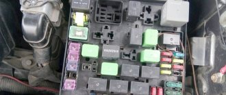
basic information
Fuses in a UAZ Bukhanka car are located in a special mounting block, which in turn is located in the air inlet box on the left side of the vehicle. The mounting block includes all the most important sections of electronic circuits, while supplying them with the necessary fuses and relays. The fuse box of the UAZ Bukhanka car consists of two lines with fuses and this entire structure is secured with a nut to the vehicle body. If you decide to remove the fuse lines, you will need to disconnect the battery.
The main elements of the electronic circuit include:
- Accumulator battery;
- Electronic fuel pump;
- Fuel mixture purification filter;
- Injectors;
- Engine control unit;
- Electronic ignition coil;
- Spark plugs;
- Idle speed sensor;
- Crankshaft sensor;
- Air damper sensor;
- Tachometer;
- Fan motor cooling the radiator;
- Electronic fan motor control relay;
- An indicator that monitors engine performance;
- Diagnostic connector.
If any failure of electronic equipment occurs, the current in the node that is responsible for this device will increase, resulting in a short circuit. The wire through which the current passes to the fuse burns out and melts, as a result of which the circuit breaks and the device turns off, but its integrity is maintained. That is, thanks to fuses, the main parts are protected from overheating in the event of a short circuit.
How to properly remove and install the mounting block?
If the electrical circuit is made with high quality, it will greatly facilitate the process of installing and removing electronic equipment. So, the algorithm for removing the mounting block:
- Disconnect the wiring from the negative terminal of the battery;
- Open the hood and remove the cover from the fuse and relay box. To do this, you need to press out 4 plastic latches;
- Move the rubber cover;
- Disconnect the upper block of the wiring harness from the block;
- We unscrew the 2 nuts that secure the block;
- We take out the block from the compartment, which is located in front of the windshield;
- We disconnect the lower blocks of the wiring harnesses from the block;
- Install fuses and relays in reverse order.
Repairing the mounting block involves replacing printed circuit boards. So, the algorithm for repairing the mounting block:
- Remove the mounting block;
- Remove the 8 screws that secure the bottom cover;
- Using a screwdriver, open the bottom cover;
- We check the condition of the tracks along which the current passes and the quality of soldering. If defects are detected, they must be eliminated, but if this is not possible, then completely replace the unit;
- Install the mounting block in reverse order.
Main components and operating principle of the engine starting system
To understand the operation of the starting system, it is worth first considering the design of the car starter. The purpose of the starter is to start the engine. The starter device for all cars is identical, they differ only in size or parameters. So, the design consists of the following required elements:
- Electric DC motor;
- Bendix;
- Starter solenoid relay.
The main role here is played by the electric motor, and the bendix and starter relay are auxiliary elements. The electric motor includes standard elements such as a stator, a rotor, and a starter brush assembly. Bendix, even the smallest detail, plays a very important role. It is necessary to transmit rotation from the electric motor to the gear ring of the engine flywheel, thereby ensuring starting.
Until 2000, the bendix was located on the same shaft as the rotor, and then a new arrangement appeared, where the bendix began to have its own separate shaft and rotate through a gearbox.
That’s why we sometimes hear the name “gear starter”. The starter retractor relay is a more complex element and performs several functions at once:
- Redistribution of electricity supplied from the battery between the electric magnet of the starter relay and the electric motor;
- Synchronization of the operation of all components when starting the engine;
- Feeding the Bendix gear until it engages with the flywheel ring gear;
- Returning the working gear to its original position after starting the engine.
The principle of operation of the starter is as follows: in order to start the car engine into operating mode, it is necessary to forcibly rotate the crankshaft until the fuel mixture in the cylinders begins to burn.
Typically, it takes quite a bit of time to start a working engine. The task of the starter retractor relay is to maintain the engagement of the Bendix gear with the flywheel and rotate the crankshaft equally until the start occurs. No more and no less. If you hold it longer, you can break parts, and if you hold it longer, the engine won’t start.
Fuse pinout
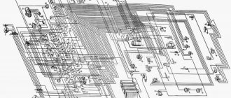
From the figure above it is clear that the factory circuit does not have a fuse panel or even relay indicators.
You can figure out exactly where the wiring goes by examining the individual parts of the circuit indicated in the car's owner's manual. In addition to the above, the UAZ company is not known for its meticulousness and strict adherence to the engineers’ instructions. The location of wiring and safety equipment may vary depending on the year of manufacture and even the configuration.
DIAGNOSTICS AND REPAIR
CHECKING THE SYSTEM
Before checking the solenoid relay, you need to test the starter itself. This check will allow you to understand what exactly is not working in the system. Insert the key into the ignition and turn it.
Next you will need to open the hood and get to the starter. You must make sure that this is the case. To do this, bridge the two contacts. They are made in the form of two copper bolts. These structural elements are attached to the rear of the solenoid relay (on the body). If, after the manipulations you have performed, the mechanism rotates, then the problem is in the solenoid relay.
In some cars, reaching the starter is very difficult, and sometimes even impossible. In this case, you will have to partially disassemble the system and dismantle the device itself.
After removing the starter, place it on the ground. Place the battery nearby. Connect the leads of the two devices. In this case, the battery ground is connected to the starter ground.
When the wires are connected, the starter solenoid relay will operate. At first there will be a rather loud click. If the mechanism operates too slowly, be sure to check the contacts. This situation may be caused by the fact that they are burnt.
Perform periodic maintenance work on the starter:
1. Check the condition of the terminals, make sure they are not dirty or loose. 2. Remove the protective cover and inspect the collector, repair if necessary. 3. Open cover 13 (see first photo) from the collector side, inspect and, if necessary, clean the contact surfaces, then blow with compressed air. 4. If necessary, tighten the starter housing bolts. 5. Check the fastening of the starter to the clutch housing. 6. When using the vehicle in severe conditions, remove the starter to clean the transmission and freewheel from dirt.
Checking the retractor relay with the starter removed
It is more convenient to check the functionality of the relay with the starter removed. But before dismantling, several operations are performed to identify the problem:
- Check the reliability of the terminals, the condition of the battery, remove oxides from the contacts and terminals of the battery.
- Make sure that the wiring is securely fastened to the starter with nuts. If corrosion is noticeable, clean the contacts with fine sandpaper.
- Check the condition of the starter enable relay.
The starter is removed after disconnecting the wires that go to it and unscrewing the mounting bolts. In some cars, this operation will take a lot of effort, since the unit may be located in a poorly accessible engine compartment.
After removing the starter, it is cleaned of dirt, the oxidized contacts are treated with sandpaper, and the test begins in the following order:
- The unit is placed next to the battery, from the terminals of which there are wires with “crocodiles”.
- The positive and negative terminals are connected to the corresponding contacts on the retractor.
- The free end of the negative wire is touched to the starter housing and the result is observed:
- If there is a distinct click in the relay, then it is working;
- If the retractor does not show “signs of life,” it needs to be replaced or repaired.
WHAT DAMAGES CAN BE IN THE EXTRACTOR RELAY
Usually the whole problem lies in burnt contacts or their sticking; other faults include:
- coil burnout,
- mechanical damage,
- natural wear and tear of parts.
In the latter case, the starter solenoid relay will need to be replaced. There are a number of signs that most likely indicate that the problem is in this particular node, these include:
- After the engine starts, the starter continues to operate. This is indicated by a clearly audible buzzing sound.
- When you turn the key in the lock, you can hear a distinct clicking sound. This means that the main system starts, but the starter does not work.
- When you turn the key, the starter idles. The engine remains inactive.
These signs most likely indicate that the malfunction is related to the starter solenoid relay.
HOW TO CONNECT
Many motorists are afraid that after they repair the solenoid relay, they will not be able to connect it. In reality, the connection diagram is quite simple. Moreover, you compose it yourself.
To carry out reverse dismantling, you must first mark the disconnected terminals. This will allow you to connect everything correctly after the repair is completed. Also, before installing the relay, you need to clean the contacts. For degreasing, use a modern liquid sold in automotive stores.
REPAIR
It is worth recognizing that on machines of the same series, the starter solenoid relays are very similar. The most striking in this context is the following automobile line:
In principle, all starter solenoid relays have the same design. Accordingly, their repair process is similar. The main differences lie in the fastening systems. Also, cores can have different designs. But the general scheme is very similar.
So, in order to repair the starter solenoid relay, you first need to dismantle and disassemble it. Here, in fact, lies the main problem. In most cars, these units are non-separable. All that remains for the driver in this case is to make a replacement.
This is interesting: Installation diagram of window lifter cables for UAZ loaf
It is very important to maintain a clear sequence during repairs. Otherwise, you risk not only damaging the part or other systems, but also getting injured. The process itself consists of the following stages:
- Disconnect power from the battery.
- Clean the part from dust and dirt. Otherwise, foreign particles may get inside the unit, causing damage to it.
- Unscrew the brush assembly nut.
- Remove the contact from the bolt.
- Unscrew the clamping screws. They are the ones that connect the relay to the ground of the car.
- Unscrew the ends of the nuts.
- Divide the device in half.
- Replace the core.
- Reassemble.
Before putting the device back into the car, start it. Reinstallation should only be carried out after preliminary testing. Once everything is assembled, do a few test runs. Only after this go on the road.
WHAT ELSE CAN BROKE?
Most damage to the solenoid relay is associated with the burnout of certain of its elements. Most often, electromagnetic circuits burn out. Windings and contacts are also subject to similar destruction. In some cases, the cause of failure is metal fatigue.
However, ignition problems are not always associated with the starter or solenoid relay. If the repair does not give the desired results, check the electrical circuit. Also look at how much charge the battery has.
Every car owner can check and repair the solenoid relay. The process itself does not take much time, and its complexity in most cases depends on how conveniently the starter is located.
Share “Starter relay description purpose device repair photo video”
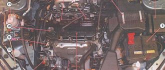
Electrical equipment
Each node is reliably protected from unexpected increases in current by special fuse links (fuses). They are assembled in a single mounting block, consisting of two lines, each of which contains 13 connectors with fuse links.
The compact unit is installed inside the car on the left side of the steering column. To make it convenient to inspect the elements of the block, a special backlight lamp with a built-in switch is fixed just above it.
In the engine compartment of the UAZ Hunter, another block is mounted, with strip-type fuses.
Each insert is responsible for a specific direction:
- starting switch;
- lighting fixtures outside the car;
- fuel filter heating;
- spark plug operation.
The purpose of the fuse links of the first and second blocks is to protect the electrical circuits of the equipment from overload and short circuit. Fuse housings come in different colors and are marked with the rated current.
The fuse links of the mounting block are installed in the following order.
Car starter connection diagram
A lot of time has passed from the time the car was created, or rather the introduction of a starter into it, to the present day, but the scheme has remained virtually unchanged. The first connection diagram for the starter looked approximately as shown in the figure below, now it has changed a little, which I will explain below.
The battery positive (1) is connected by a thick wire to the starter terminal (3). The starter current at start-up can reach hundreds of amperes. Next, the plus, through the generator (2), is supplied to the ignition switch (5). After closing the ignition switch contacts, the intermediate relay coil (4) is energized, which closes its contacts. One of the relay contacts is connected to the positive wire, therefore, after their closure, the windings of the solenoid relay are energized. We will look at how the starter and solenoid relay work in another article.
Such schemes were used in Soviet-made cars; foreign cars, if they used them, moved away from such schemes very quickly. The first starters were massive and had low efficiency. Consequently, the control circuits required the same not small currents. An intermediate relay is used to pass these currents. Modern starters have less power. This was achieved by using permanent magnets on the stator poles and installing a step-down gearbox on some models. This made it possible to get rid of the intermediate relay and supply voltage from the ignition switch directly to the coils of the solenoid relay.
Computer keyboard circuit Starter blocking device Simple starter blocking Power supply for 9-volt radio equipment from the car's on-board network Circuit of a desulfating charger Simple stabilized power supply with super-available parts Laboratory power supply controlled by a microcontroller Laboratory power supply from an AT power supply Power supply from an uninterruptible power supply
Safety precautions when performing work
When replacing electrical fuses, it is necessary to use tweezers made of non-conducting materials. This will prevent voltage transfer from the circuit to the adjacent electrical fuse.
Before replacing, you must make sure that there is no short circuit in the circuit. A new electrical fuse is installed with the power circuit turned off. When installing, you must pay attention to the amperage indicated on the product. Installing a more powerful product can lead to overheating and fire of the insulating layer of the wiring. An element with a lower current rating will not withstand the load of the electrical circuit and will burn out.
Installing a homemade electrical fuse (bug) is strictly prohibited. The maximum load of such a device has not been determined. If a short circuit occurs, it may cause a fire.
From the above it follows that the fusible element block of the UAZ Hunter car is necessary to protect the electrical wiring from overloads and short circuits. The models are equipped with two blocks, the location of which is described above. Some car modifications are equipped with an additional unit.
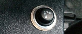
How to make a start button instead of an ignition key in a car with your own hands
Oddly enough, this issue very often worries motorists and not only for aesthetic reasons - in the spirit of the times. The contact group located behind the ignition key very often fails, and changing it is far from an easy task.
In older cars, often the wires from the starter itself are connected directly to contacts inside the contact group, which close when the ignition key is turned. When the starter is activated, a very large amount of energy is consumed, which means a large current flows (the contacts strike a spark). Over time, a burnt deposit forms on the contacts or they completely burn out, no longer providing reliable contact. Newer vehicles have a separate relay that closes the starter contacts when the ignition key is turned.
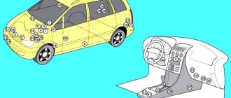
Engine compartment
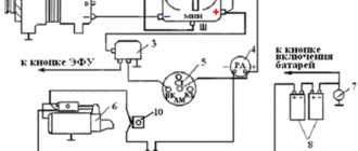
For many years, the main power unit of the UAZ 469 was the in-line 4-cylinder UMZ-451MI carburetor type. The engine capacity was 2445 cc. cm, power – 75 hp.
With this engine produced by the Ufa Motor Plant, the UAZ 469 lasted on the factory assembly line until 1985.
It was distinguished by a simple single-wire 12-volt ignition circuit, which consisted of (according to the numbering):
- rechargeable battery (AB);
- mechanical ground switch;
- electronic battery charge voltage regulator;
- alternator;
- ammeter on the instrument panel;
- ignition switch (switch);
- ignition breaker contact group;
- directly to the ignition distributor (distributor);
- capacitor built into the distributor;
- ebonite distributor cover with leads for high-voltage wires;
- ignition distributor slider;
- spark plugs;
- high voltage wires from the ignition coil;
- additional coil resistance;
- starter relay;
- directly to the high-voltage ignition coil;
- electric starter.
New modifications of the legendary SUV received more modern engines and a modified electrical circuit.
In particular, the UAZ Patriot wiring diagram includes:
- electronic fuel injection system;
- contactless ignition system;
- climate control system inside the car;
- alarm system, etc.
The main advantages of using a relay in the starter power circuit:
— Such a system is more reliable, since the relay is designed for high currents and lives much longer. — The relay can always be replaced — The contact group behind the ignition key works for a very long time, since it only turns on the relay that takes the main load.
Regardless of whether your starter is turned on by a relay or directly by a contact group, all operations to connect the starter are still performed by turning the key.
First you need to determine which contacts are responsible for the start and connect them to the start button.
To do this, you need to disassemble the plastic protection under the steering wheel of your car. Very often, a connector with all the necessary wires is connected to the contact group of the key well at the back. There should be locking tabs on both sides of this connector. You need to press on them and pull out the connector.
If you have an old car, inspecting the contact group connector you will most likely find the two thickest wires. Very often one of them is red - these wires are directly connected to the starter. If you connect them with the ignition key turned, your starter will most likely start spinning.
Then you can go the simple way. You can simply install the button and connect these two wires to it, placing the button in a place convenient for you. The button should be non-latching, that is, when pressed, it should close the contacts, and immediately after you release it, open it.
Do not forget that you will operate the button in the same way as a key. We press the button, wait until the starter spins, and as soon as the engine starts, release the button.
But do not forget that very large currents will pass through the button and most likely such a button will burn out.
We used a vandal-proof chrome button - it failed after about half a year.
If you have a newer car and the starter in it is connected using a relay, you will need to find among the many wires exactly those that are responsible for controlling the relay.
To do this, you can ring the tester in resistance measurement mode on all the wires on the car body. All wires that ring are marked as ground (or minus), since they are all shorted to the body.
Next, touch each of the remaining wires with one tester probe and the other probe to the body in voltage measurement mode.
We need to find the wire on which 12 Volts appears exactly at the moment you turn the key, that is, when your starter starts spinning.
If you find this contact, you need to check how the system works.
— Find some kind of contact on which, relative to ground, there is always 12 Volts.
— Turn the ignition key to ignition mode (the starter must be turned off)
— Check again the wire you found:
* check that it is not connected to ground and is not short-circuited to the body,
* check that voltage appears on it when you turn the key to the starter mode
- Now try using a separate wire to connect the wire that you found in the paragraph above to the wire that always has 12 Volts.
If after connecting your starter turns over, then you have found the wires that connect when you turn the key so that the starter turns over.
Your work is finished here. You just need to bring these wires to a convenient location on the dashboard and connect the button to them.
If your car is an old model, it is best for you to install a separate relay to turn on the starter and close only the relay contacts, which in turn will connect the starter contacts.
You can see which contacts are responsible for what on the relay body, or you can open it and see how it works.
Oddly enough, it makes absolutely no difference where to connect + (plus) and where - (minus) on the contacts of the relay coil - in any case, it attracts the desired contact and connects the line.
That is why you can use the positive contact with 12 Volts already connected to the relay. It can be connected to the coil contact. Accordingly, the second contact is connected to ground through the button.
It is these two wires - minus (ground) - the second contact of the coil that must be brought out in a place convenient for you and the button connected to them.
The remaining relay contacts for the main line must be connected to the wires on the contact group that connect the starter.
Don't forget about high power when connecting these wires. The wires must be very thick and the connections very secure.
The wires can be directly soldered to the relay contacts, but most likely this will be a mistake, since it will be quite difficult to replace it later. In our case, when heating the contacts with a soldering iron, they melted the plastic body of the relay and moved, closing the contacts inside the relay.
It is best to find a remote connector for such relays, which is sold separately. Unfortunately, it does not please with its reliability or quality of workmanship.
The wires on the connector pins are very thin and very difficult to hold on to. We recommend that you remove each pin and solder secure thick wires to them.
For convenient connection, you can attach screw terminals to the wires.
It is best to place the relay in a place where it will be convenient for you to reach it later to replace or check the operation of the system.
Remember that you do all the above actions at your own peril and risk; we do not recommend that you undertake such complex electrical work if you do not have skills in electrical engineering. We wish you good luck in all your endeavors.
Replacing a damaged electrical fuse
Before replacement, it is necessary to determine the reason why the protection tripped. If there is a short circuit in the circuit, the fault must be eliminated. If there is a short circuit, the procedure for replacing the electrical fuse with a new one is impractical. The product will burn out after being connected to a short circuit.
To replace you need:
- Find the electrical fuse box on the left side of the driver's wheel;
- Remove the protective cover with the lock installed on it;
- Turn on the lamp installed at the top of the product;
- Using the electrical diagram, determine which electrical fuse needs to be replaced;
- Remove the faulty product from the seat;
- Select a new product with identical face value;
- Install a new product into the cell;
- Check the functionality of the power supply circuit;
- Place the cover in place.
To replace the power fuse:
- Open the engine compartment of the car;
- Find the power products block on the panel of the power unit compartment;
- Remove the protective cover;
- Using the diagram, determine which element has failed (this can be done visually after opening the lid; parts of the burnt plate will be separated);
- Unscrew the nuts securing the plate;
- Dismantle the damaged product;
- On the inside of the cover, find a plate corresponding to the current strength of the dismantled part (the rating is applied to the plate by imprinting);
- Install the part onto the fastening studs;
- Secure the plate with nuts until it stops.
IMPORTANT: The power fuse nuts must be securely fastened. Loosening the nuts leads to poor contact and overheating of the product.
How to connect a starter relay: rules for connecting a relay
As you know, normal functioning of a car is impossible without a good and clear start. When setting up the electric starting system of a car, great importance should be paid to the “starter-relay” circuit. It is important to know how to connect the starter relay so that no difficulties arise in the entire starting system.
Main starter relay
The car's electric starting system includes, in addition to the starter and relay, also starter on/off elements, various connecting wires, the main power source (battery), etc.
The starter relay or VR is activated after turning the key in the ignition switch. The BP armature and the freewheel lever move, and the bendix engages with the flywheel crown. This ensures normal engine starting.
How to properly connect the starter relay
To be able to adjust the system, you need to disconnect the current wiring from the VR. The control terminal is marked on the terminal with the letter M.
Then the battery is removed from its original place and connected to the M and S terminals marked on the terminals. Thus, the purpose of the operation performed is to shift the bendix. And in order to connect the BP to the starter, you must first adjust the gap between the bendix and the stop. It is also recommended to adjust the gasket located between the drive and the BP.
Additional VR starter
On modern cars, an additional VR starter is a priori provided. On older cars, the relay is installed and connected independently.
The advantages of installing an additional VR are obvious:
- Protects the starter device from burnout of contacts in the lock, which occurs for various reasons (long start-up, banal wear, etc.);
- It has a positive effect on the loading of contacts of the same ignition switch, as a result of which the contacts remain operational longer;
- Protection of the starter from a situation where, due to a “glitch” of the key in the ignition switch (the engine has started, but the starter continues to spin).
This is interesting: Wiring diagram for VAZ 2114 power windows
How to connect the additional starter relay
You can check whether the additional VR is installed on the car like this:
- Look in the “black box” (fuse box);
- Turn on the starter device in the engine purging mode - if the additional relay is on, then the starter must turn off on its own after a few seconds.
Connection of additional VR
Here's how to connect:
- Fix the relay in any convenient place (you can on the stud of the glass cleaning fluid reservoir);
- Connect the cable to the starter;
- Remove the red wire from the flat terminal of the main relay, and in its place insert the wire from the additional VR;
- Connect the other wire of the new BP with an 8 mm tip to the positive of the starter;
- Place contact 30 of the additional VR onto the released contact of the main VR;
- Screw the short wire numbered 85 to the body (ground).
Additional relays can be purchased in stores. They are sold as a kit, where everything is provided for proper self-installation.
How to pay TWICE LESS for GASOLINE
- Gasoline prices are rising every day, and the car's appetite is only increasing.
- You would be happy to cut costs, but is it possible to live without a car these days!?
But there is a completely simple way to reduce fuel consumption! Don't believe me? An auto mechanic with 15 years of experience also didn’t believe it until he tried it. And now he saves 35,000 rubles a year on gasoline! Read more about this at the link.
Historical reference
Traditionally, the UAZ 469 was produced in two versions:
- Cargo-passenger version - 7 seats and 100 kg of luggage;
- Commander version - 2 seats for passengers and 600 kg of luggage.
Industry standard 1945
According to the old vehicle classification system, in force since 1945, the UAZ 469 was produced under this name, using an alphanumeric name:
- The letter abbreviation UAZ stood for Ulyanovsk Automobile Plant;
- 469 is a serial factory index assigned by the enterprise itself to its models and developments.
1966 Industry Standard
Although at the time of the release of the UAZ 469 (1972) a new industry classification system was adopted (industry standard OH 025270-66), the car plant continued to use the name according to the old standard.
However, in 1985, the automaker was forced to change its name in accordance with current requirements:
- the car was assigned a four-digit number - 3151;
- According to the new system, the car can be called in the documentation as UAZ 3151.
The car plant named all further modifications and new models in accordance with current standards. In particular, the UAZ Patriot, which appeared in 2005, according to the industry classification, received the “correct” designation - UAZ-3163. For greater identification, the factory instructions contained both names.
What does it mean “the starter takes over the current”?
The main reasons why the starter can take on current are:
- Lack of good contact on electrical wiring and elements of the ignition system;
- Sufficiently low electrical or high mechanical resistance;
- Failure of the constituent elements (due to the deterioration of the bushings, the armature begins to touch the starter when rotating). This leads to strong heating and destruction of parts. The gearbox also needs to be checked, because it may also need additional lubrication.
Your actions
To understand the true reason, it is necessary to carefully study the mechanism and check all its elements. The first step is to determine the location of this mechanism. Access to it is usually very limited, but you can get it by hand. It is also important to make sure that the battery is charged, since drivers often leave the car with the headlights on, and their work greatly drains the battery.
If the battery is in perfect order, then you should check the starter, for this you will need a power class=”aligncenter” width=”600″ height=”402″[/img] So, a thick wire is supplied from the battery to the starter, which is connected to a large bolt on relay (this is the positive terminal). You need to connect the positive contact of the multimeter to it, as a rule, this is the red wire. And the black wire with a negative contact must be connected to the ground of the car. And when you turn the key in the ignition, check what the instrument display shows. If the battery is working well, the voltmeter will show twelve volts, and the starter will make characteristic clicks. If clicks occur and the display shows less than twelve, then perhaps the reason is not in the starter, but in the battery or ignition switch.
To check the malfunction, you need to purchase a long screwdriver with a well-rubberized handle. Next, you need to disconnect the wire that comes from the ignition switch from the solenoid relay. Next, you need to short-circuit the positive terminal with the bolt from which the wire was removed, using the metal part of the screwdriver. This operation will allow current to be supplied directly from the battery to the relay. The car should start. If you managed to do this, then this means either the lock or the relay is faulty.
If you were unable to perform such a manipulation, this check did not produce any results, then you will have to remove it and deal with it. Before checking the relay, it must be cleaned of various contaminants. Next, connect the starter to the battery. We connect the positive contact of the battery to the relay output, and the negative contact to its body. As a result, a click should occur and the gears should begin to move. This way we know that the relay is working properly. If this operation does not produce results, then the relay must be repaired yourself or purchased a new one. The cost of the relay is not high. If you buy a new one, do not forget to buy the same one (go to the store with the old relay).
After checking the relay, I recommend checking the starter itself. There is a terminal in the place where the relay was; you need to connect the positive alligator clip from the battery to it, and the negative one to the housing. If the gear works, then the reason is in the relay. The second element that may cause poor starter performance is its armature.
The fact is that in a situation where the bendix rotates very slowly, and the battery is fully charged, it is necessary to remove the armature. Next, you need to check the housing winding and the winding short circuit - these are the main reasons for the failure of the starter armature. To check the functionality of this element, you need to use a tester and check the voltage between the windings and the rotor housing. The tester should show at least a million ohms, or even more. If the data is lower, the anchor needs to be replaced.
From my experience I know that checking the bendix, brushes and windings play an important role in the good performance of the machine. If the relay does not work, then it is necessary to check the brushes and the winding. To check, you need to use a regular light bulb (12 Volts) with two wires that are connected to the brush holder and to ground. When checking, the starter must be connected to the battery. If the lights come on, this means that the brushes are faulty. In the same way it is necessary to check the winding.
It is important to remember that if several starter elements break down at the same time, it is advisable to purchase a new one rather than try to replace one part at a time.
If one part fails, then it needs to be replaced. The new part must be identical to the part being replaced. It is not advisable to purchase analogues; this may lead to undesirable consequences in further work.
Video “Checking current leakage”
The recording shows how you can check at home whether there is a current leak on a JEEP car.
Every 32,000 km of the vehicle, perform the following maintenance work on the starter:
1. Remove the starter from the engine. 2. Check the condition of the commutator and brushes. Make sure the brushes do not get stuck in the brush holders. If the brushes are smaller than 6mm, replace them. 3. Remove the starter. Replace worn parts. 4. During assembly, lubricate the bearings and shaft journals with engine oil. Lightly lubricate the splined part of the shaft, the bushings of the transmission branch, the fingers and the lever axis with Litol-24 grease
When I was looking for why the starter might not work, I found this picture from the manual for UAZ cars.
And today, while my girlfriend was driving the Sotka and it went out, our ignition stopped responding, since it was still left in the morning, after flushing the engine, a new relay was bought in advance, the seller said that all relays cost the same, I believed him and bought a standard five-pin relay.
But that was not the case, the circuit of the standard relay is completely different. And when I tried to turn on the ground, the starter began to spin, at that moment I compared the circuits on the relay. I installed the dying relay, pushed it, started it, and drove all day. There, at my request, provide the necessary relay and after showing a photo of what was needed, with a detailed explanation of the operation diagram:
They looked at me as if they were testing me, said that the factory makes the same relays for everyone, and gave me the relay as in the first photo. In response to my attempts to explain that the circuit is not the same and that when the mass is turned on, the starter begins to spin, they affectionately hinted that my hands were growing out of my ass, I didn’t need an electrician. I didn’t fight, I just turned around and went to the store, which was much further away, they immediately understood me and gave me what I needed. By the way, I connected the wires and plugged them into the old relay. If anyone is interested, I found a wonderful diagram on the Internet, according to which, even without the color of the threads, you can understand what and how.
Since for some time I have been faced with the problem of the color of my wires not matching some circuits, here are the contacts that correspond to the colors of my wires (UAZ 31519, motor 421800)
30 - orange + purple 85 - red 86 - black 87 - purple 87b - white
The UAZ starter is a necessary mechanism for starting the vehicle’s power unit.
How to hook up a button to the starter via a relay and connect
Today, drivers of old cars often want to see a convenient button on the instrument panel that can easily activate the starter. They want such modernization not only for aesthetic purposes, but also for purely practical ones. We will learn from the article how to connect a button to the starter via a relay.
Contact vulnerability
In cars manufactured more than ten years ago, the starter wires are always connected directly to the ignition switch contacts. The engine starts only after the driver turns the ignition key to the extreme position.
This option for connecting the starter is simple and effective. But contacts are always a problem. Moreover, when the starter device is activated, a huge amount of voltage is generated, causing sparking. Where there is a spark, the contacts burn out, oxides accumulate on them, etc. As a result of this, over time, problems arise with starting the engine; motorists are looking for alternative ways to turn on the starter, including directly from the battery.
How to connect a starter via a relay
As you know, in cars of recent years of production, which do not have a button, an additional relay is provided that controls the starter. In this way, the lock contacts are relieved, which now bear less of a load.
- Systems with a separate relay are more reliable because they last longer.
- The ignition switch contacts also “live” much longer.
- An additional relay can always be upgraded.
How to connect a button to the starter
However, the topic of this article is connecting the starter via a button connected to the same relay. How can this be accomplished?
Connecting a button in a car where there is no additional relay
First of all, you should find the contacts responsible for turning on the starter. Then integrate them with the button.
The modernization algorithm generally looks like this:
- The plastic trim under the steering wheel is disassembled;
- There is a connector connected to the ignition switch contacts (as a rule, this connector has locking tabs);
- Press the tabs to release the connector and pull it out.
As a rule, on older cars, after inspecting the connector, two cables with a large cross-section are found. The red one is responsible for controlling the starter.
Note. You can check whether the wiring is really responsible for controlling the starter like this. Turn the ignition key all the way, short-circuit both wires from the removed connector. If the starter turns on, then that's what they are.
- The button is placed in a place convenient for the driver;
- The found wires are connected to it.
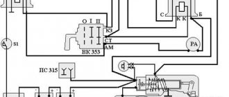
Electrical wiring components for UAZ 469, UAZ 390945 and other models
The electrical circuit of the UAZ 3151 4 includes 69 positions; it is possible to additionally connect special fog lights, but the installation of a switch type 343.01.03 is required. It will be mounted directly on the dashboard in a convenient location. The general wiring diagram of a machine includes an extensive list of different devices.
This is a front light, headlights that are easy to replace if necessary. An audio signal is also connected to the general system. Further, the UAZ wiring diagram includes a special fuse and additional resistance. The circuit has a connection to the side direction indicators, and a switch for the heater is located right there.
The wiring supplies the generator, there are connection points for the light that illuminates the engine compartment, and outputs for the heater fan motor. Modern UAZ electrical wiring includes spark plugs powered by it. A relay is installed for indicators; it is used to ensure the operation of emergency and turn signals.
The electrical circuit has outputs to a coil, a starter relay, there is a special sensor-distributor, and a switch. In one area there are the following points: turn off the masses, hazard warning lights, battery, electric washer. There is a separate connection for the fuse box and the following sensors:
- emergency pressure for oil;
- fuel readings;
- for oil pressure indicator;
- overheating of used coolers;
- temperatures of the coolers used;
- determining the brake fluid level.
1.Low voltage ignition coil; 2.Transistor electronic switch; 3. Sensor-distributor (distributor); 4.Electric spark plugs; 5.Fuse block; 6.Emergency breaker; 7.Additional electrical resistance.
The electrical diagram includes connection points for the starter, speedometer, windshield wiper and relay for it, EPH unit, voltmeter. There are the following components:
- relay for car headlights;
- sockets used to power portable lamps;
- parking brake switches, braking systems.
For electrical equipment of UAZ 31512(14) or UAZ 390945, the following switches are installed:
- for brake signal;
- for parking brake;
- alarm;
- interior light lamps;
- sound signal;
- rear fog lamp;
- ignition;
- reverse lights.
The electrical equipment of UAZ-31512, UAZ-31514 and UAZ-31519 vehicles is made according to a single-wire circuit. The negative terminals of the sources and consumers of electricity are connected to the body and other components of the car, which act as a second wire. On-board DC network, with a nominal voltage of 12 Volts. Protection of electrical circuits is organized through a fuse box.
To switch the main circuits of the car, a combined ignition switch is used, consisting of a contact part and a mechanical anti-theft device with a lock. When the engine is not running, all consumers are powered by the battery, and after the engine is started - by alternating current with a built-in rectifier unit. When the generator is running, the battery is charged.
When the engine is idling, the generator rotor speed and, accordingly, the supplied current are insufficient to provide power to powerful consumers, such as headlights, windshield wipers, electric fans, and alarms. In this mode, the battery will be discharged.
To protect the vehicle's external lighting electrical circuits from overload, a bimetallic fuse 29.3722 or similar is used, which is installed under the instrument panel on the left. Three 10 Amp fuses are installed in the PR103 fuse box, mounted on the partition of the engine compartment. They protect:
No. 1 – circuits of control devices; No. 2 – direction indicator circuits; No. 3 – alarm and sound signal circuits.
Fuse No. 1 is located closer to the right side of the vehicle. The heater fan motor power circuit is protected by a fuse with a rated current of 6 Amps. The fuse is located on the wiring harness next to the heater switch. UAZ-31512, UAZ-31514 and UAZ-31519 vehicles can be equipped with other additional fuses, depending on the configuration.
What is included in the electrical circuit
The above is a form of electrical wiring diagram.
Regardless of which UAZ you use - old or new model - the main components of the electrical network are as follows:
- Dashboard. It displays the main sensors and indicators indicating that a particular device is turned on. Tidying allows the driver to know at what speed he is moving, how much fuel is left in the tank, what the crankshaft speed is and what the engine temperature is. In addition, there are many lights installed on the tidy that light up synchronously with the switching on of certain devices.
- Accumulator battery. The battery is an integral element of any car; it allows you to power the vehicle’s equipment when the engine is turned off, and also helps the ignition system in starting the power unit. If the battery is discharged, you will not be able to start the engine in the traditional way - you will either need to recharge it or try to start it with a pusher.
- A generating device, the failure of which will also make it impossible to start the engine. This unit provides voltage to all devices and devices used in the car while driving.
- Fuse block. This device contains all the safety devices designed to protect electrical circuits and devices from overvoltage. If there is a power surge in the network, then the main blow will be taken by the fuse (author - Ben & Ice Video Master channel).
Source
Where is the charging relay located?
The charging relay consists of a reverse current relay, a regulator and a limiter. The reverse current relay turns the generator on when its voltage increases, and turns it off when the battery voltage increases.
The regulator controls and limits the current within 13.8 - 14.8 V , and regulates the charging current. The limiter protects the generator from overloads, working on a similar principle to the voltage regulator - it includes additional resistance in the winding circuit as the current increases.
The charging relay works in conjunction with the alternator under the engine hood on the right side.
Device
The UAZ 469 starter, number 42.3708, consists of the following elements:
- drive side cover;
- driving ring;
- thrust ring;
- lock ring;
- drive unit;
- anchor;
- frame;
- brush;
- traverse;
- thrust washer;
- adjusting washer;
- lock washer;
- manifold side cover;
- contact bolt;
- contact plate;
- relay cover;
- return spring;
- stock;
- relay armature;
- compensating spring;
- buffer spring;
- gear;
- screw M5x14;
- tie rod nut;
- screw M6x16;
- M8 nut;
- relay coil input;
- screw M6x30;
- lever arm;
- M8 nut;
- lever axis.