All modifications of T-150 tractors are equipped with diesel six-cylinder four-stroke supercharged SMD-60 engines with a 150-horsepower rated power. They were developed specifically for these machines, have a V-shaped arrangement of cylinders and liquid cooling.
V-shaped 6-cylinder diesel engines have been produced since 1972. The engines are installed: SMD-60, SMD-61
- Tracked agricultural tractors T-150, T-153 and forestry skidding tractor T-157.
SMD-62, SMD-63
- Wheeled agricultural tractors T-150K, T-151K and industrial tractor T-158.
SMD-64, SMD-65
– Combine harvester SK-6 “Kolos”, machine for harvesting table root crops MUK-1.8.
SMD-66
- Crawler agricultural tractor DT-175S
SMD-72, SMD-73
- Forage harvesters KSK-100, KSG-F-70 and corn harvester KSKU-6.
What is the order of operation of the cylinders of the SMD 62 engine
4. STRUCTURE AND OPERATION OF COMPONENT PARTS OF THE TRACTOR
4.1. STRUCTURE AND OPERATION OF DIESEL SMD-62
The SMD-62 diesel engine is four-stroke, six-cylinder, with a V-shaped arrangement of liquid-cooled cylinders, direct fuel injection and turbocharging.
A diesel engine consists of a block crankcase, two cylinder heads, a crank mechanism, a distribution mechanism, components and assemblies of fuel supply systems, air supply, lubrication, cooling, exhaust
gases, as well as components and assemblies of the starting motor and gearbox.
The diesel cylinders are arranged in two rows at an angle of 1.53 rad (90°) and are made in a common block together with the upper part of the crankcase. A distribution-type fuel pump with a mechanical all-mode regulator is located at the rear of the diesel engine and is driven by a gas distribution mechanism. To clean the fuel, the diesel engine has two filters: one for coarse cleaning, the other for fine cleaning. To clean the air entering the cylinders, the diesel engine uses an air cleaner with paper filter elements. A subflow oil centrifuge is used to filter the oil. The centrifugal water pump with fan and compressor are belt driven from a pulley on the front nose of the crankshaft, and the generator is driven from a pulley on the water pump.
The diesel engine is started by a single-cylinder gasoline starting engine, the transmission from which to the diesel flywheel is carried out by a single-stage gearbox.
To reduce noise, the diesel engine is equipped with a muffler.
The diesel engine has space for installing oil pressure and water temperature sensors, as well as an emergency oil pressure alarm sensor.
Each diesel operating cycle is carried out during two revolutions of the crankshaft and includes four strokes: intake, compression, power stroke and exhaust. During the intake stroke, when the piston moves from TDC. to the i.m.t., fresh air enters the cylinder through the open intake valve. When the piston moves from ground level. to v.m.t. (the intake and exhaust valves are closed), the air is compressed, and its temperature rises. At the end of the compression stroke, fuel is injected into the chamber in the piston through an injector. The fuel atomized and mixed in compressed air ignites, and the pressure in the chamber increases. The gases formed during combustion, expanding, press on the bottom of the piston, as a result of which the piston moves from top to center. to n.m.t. and through the connecting rod transmits force to the crankshaft crank, causing it to rotate, that is, a working stroke occurs. When the piston, after the working stroke, begins to move from ground level. To
V.M.T., the exhaust valve opens and the exhaust gases are pushed out of the cylinder by the piston, the exhaust stroke occurs. After exhaust gases are released, the cycle repeats.
The working strokes in diesel cylinders follow one after another in the order of cylinder operation 1-4-2-5-3-6.
For a better workflow, the opening and closing of the intake and exhaust valves do not coincide with the position of the piston at dead centers. The valve timing is shown in Fig. P.
Advancing the opening and retarding the closing of the intake valve ensures better filling of the cylinder with fresh air, and the exhaust valve ensures more complete removal of exhaust gases from the diesel cylinder. Due to the constant improvement of diesel engines, there may be some changes in the description of the design of individual assembly units and parts.
Source
contents .. 41 42 ..SMD-62 ENGINE POWER SYSTEM
Sequence of task execution:
1. In Fig. 4.10 consider the power supply system diagram. Locate all system devices on the tractor. Trace the path of the fuel from the tank to the injectors. Consider how the tank and power system devices are attached. Study and remember the order of connecting high-pressure fuel lines from the pump to the injectors (Fig. 4.10, b).
2. Using a poster or textbook, trace the path of air through the air cleaner. Find the first stage of purification - the cyclone unit.
Understand the working principle of a cyclone. Locate the location where dust is sucked out of the air cleaner. Consider the second stage of cleaning - a cassette with a metal or nylon “tangle”.
On the tractor, consider the location of the air cleaner, the dust suction tube connecting it to the exhaust pipe. Locate the tube leading to the compressor.
Find the air entry point to the cyclones. Using a cross-section of the air purifier, study how cyclone 13 is constructed. Study how the joints of the cassette with the lid and casing, and the lid with the casing are sealed. Consider how a cassette with a “tangle” is arranged.
3. On the engine, consider the location of the turbocharger and its connection to the air cleaner and air purifier, as well as to the exhaust manifold. Using the textbook, trace the path of the exhaust gases in the turbine and the air in the compressor. Examine the design of the turbine guide vane. The entrances to the turbine housing are made so that the gases press on the turbine wheel from both sides.
Please note that the turbine housing is connected to the exhaust manifold pipes by corrugated transitions. Think about why they are corrugated. Locate the oil line on the engine that goes to the turbocharger bearings.
Rice. 4.10. Diagram of the SMD-62 fuel system: a - interconnection of fuel system devices; b - connecting high pressure fuel lines to the pump heads; 1, 2, 6, 7 and 8 - fuel drain lines; 3 — drain fuel line of the fourth injector; 4 and 9 ^ - high pressure fuel lines; 5 - nozzle; 10 — high pressure fuel pump; 11 — fuel outlet pipe; 12, 15, 17, 19, 23 and 25 - low pressure fuel lines; 13 — fine filter; 14 - bypass valve; 16 — drain pipe for bleeding the system; 18 — control filter; 20 — fuel tank; 21 - pipe for draining fuel from the filter; 22 — booster pump; 24 - coarse filter
Rice. 4.11. SMD-62 fuel system filters: a - coarse filter; b — fine filter 2TF-3; 1 - cover; 2 — fitting of the fuel inlet pipe; 3 - nut of the coupling bolt; 4 - air release plug; 5 — bracket; 6 - distributor; 7 - gasket; 8 — guide cone; 9 - glass; 10 - pacifier; 11 - drain plug; 12 - filter; 13 — bolt-sleeve; 14 - clamping ring; 15 - spring; 16 — washer; 17 — filter element; 18 — filter washing valve; 19 — valve for releasing air from the fuel system
Rice. 4.12. Pump ND-22/6: a - pump assembly; b - pumping section; 1 - pumping section; 2 - high pressure fuel line; 3 — breather; 4 - intermediate gear; 5 — regulator shaft; 6 — regulator body; 7 — regulator cover; 8 — corrector; 9 — tachometer speedometer drive housing; 10 — eccentric shaft; 11 - drive gear; 12 - cam shaft; 13 - hole for draining oil; 14 — mounting flange; 15 — injection advance clutch; 16 — pressure fitting; 17 - head; 18 — inlet window; 19 — sleeve; 20 - plunger; 21 — dispenser; 22 — toothed bushing; 23 - spring; 24 — lower spring plate; 25 — pusher; 26 — upper spring plate; 27 — dispenser drive; 28 — discharge channel; 29 — unloading valve; 30 - discharge valve; 31 — discharge valve spring; 32 — limiter; 33 — installation pin; 34 - coupling nut; 35 — intermediate gear bracket
Consider the location and direction of the compressor wheel blades and compressor insert guide vanes. Think about why the shoulder blades are tilted in different directions (as if towards one another).
Consider the location of the turbine wheel blades, as well as the guide vane blades. Please note: the shape of the guide vane blades on the compressor part is not the same as the shape of the turbine part blades.
4. Study the design of the fuel tank.
5. According to Fig. 4.11 study the fuel coarse filter FG-2.
Trace the path of fuel in the filter and how it is cleaned.
Getting into the cavity of the glass, it passes through a narrow gap between the wall of the glass and the reflective cone. This leads to a sharp increase in the speed of movement of fuel with mechanical impurities. After the cone, the fuel sharply changes the direction of movement, and heavy impurities continue to move downward by inertia and fall under the damper, which prevents the stream from agitating the sludge. Clean fuel passes through mesh 12 of the cone and exits through hole B to the booster pump.
6. Consider the mounting of the booster pump. Study the design and operation of the pump.
7. Examine the fine fuel filter (Fig. 4.11, b). Disassemble one section (the rest are arranged similarly). Remove the plastic cup 9 along with the filter element
, retaining spring 15 and elastic sealing washer 16.
There are input channels on the filter cover that are connected to valve 18 for switching sections when washing filters. This valve has three positions: working - fuel flows parallel to both sections; position I - the right section is closed, uncleaned fuel is sent only to the left section; position II - the left section is blocked, uncleaned fuel goes only to the right section. The switched off section is washed with clean fuel from the operating section.
Find the output channels of both sections. Purified fuel comes out of them through one fitting.
The filter element is made of special filter paper about 2 m long. It is rolled into a cylinder, which is folded like an accordion. The ends of this cylinder are closed with tin lids. The cylinder is protected by a thick cardboard shell with holes. The element is put on the coupling bolt. Spring 15 and gasket 16 ensure that the element is tightly pressed against the lid and glass, which prevents the leakage of unclean fuel from the housing cavity to the outlet channel.
At the bottom of the body there is a drain valve bolt with a locking ball, which is pressed by bolt 11.
8. Using the poster, study the structure and operation of the fuel pump. The engine is equipped with a distribution type pump ND-22-6. The pump has two sections, each of which operates three cylinders. The section includes a plunger pair - plunger 20 (Fig. 4.12) and sleeve 19. An adjusting dosing coupling 21 is put on the plunger. On sleeve 19 in its upper part there are two inlet 18 and three outlet holes, combined with discharge channels 28. the sleeve is installed on top of the head 17, which is centered with a pin 33 and tightened with a coupling nut 34. Three drillings are made in the head to the sockets into which pressure fittings 16 with injection valves 30 are screwed. Fuel lines are attached to the fittings.
The plunger is lowered by spring 23, and raised by pusher 25 when cam 12 runs onto it. The cam has three protrusions and lifts the plunger three times in one revolution of the cam shaft. At the same time, the plunger rotates around its axis through the toothed sleeve 22 and gear 4. Gear 4 is rotated by the gear of shaft 5 of the regulator.
The work of the plunger pair is as follows. When moving downward, the plunger opens the inlet holes 18, and the fuel located in the inlet cavity is under pressure
0.15 MPa, fills the space above the plunger (Fig. 4.13, a, I): When the plunger moves upward, at the moment when it blocks the inlet holes, a closed volume is created in the space above the plunger, and the pressure increases sharply. At the same time, due to the rotation of the plunger, distribution drilling B approaches one of the output channels 28 in the head, and fuel begins to flow through this channel to the discharge valve 30, opens it and is directed to the nozzle
(Fig. 4.13, a, b, III). Fuel will be pumped to the nozzle until the transverse drilling B of the plunger comes out of the dispenser 21 (Fig. 4.13, a, IV). In this case, the above-plunger cavity will connect with the low-pressure cavity around the dispenser, the pressure above the plunger will drop sharply, the discharge valve will close, and the fuel supply will stop. With subsequent lowering and raising, the plunger will have time to rotate 120°, and fuel will be supplied through another outlet channel of the head and the discharge valve to the next nozzle. Thus, during one rotation of the camshaft of the fuel pump, the plunger rises and falls three times and rotates completely around its axis, during which it provides supply to three cylinders. The second section supplies the other three cylinders.
Rice. 4.13. Diagram of the operation of a distribution type pump plunger (a and b) and a discharge valve (c) (for positions, see Fig. 52): B - distribution drilling of the plunger; B - cut-off drilling of the plunger; G - calibrated hole of the unloading valve; I - filling of the space above the plunger; II - flow of part of the fuel into the intake channel; III - working stroke of the plunger (fuel injection); IV - fuel supply cut-off - closing of the discharge valve; V - opening of the unloading valve - unloading the high pressure fuel line
Rice. 4.14. Diagram of the pump regulator ND-22/6: 1 - 37 designations are shown in Fig. 4.12; 3 — driven gear of the regulator drive; 19 — damper spring; 40 — cross; 41 — cargo hub; 42 — cargo; 43 - coupling; 44 — lever axis; 45 — main lever; 46 — corrector lever; 47 — corrector rod; 48 — earring; 49 — main spring; 50 - regulator control lever; 51 — screw for adjusting the nominal rotation speed; 52 — minimum speed screw; 53 — emphasis; 54 - plunger rotation drive gear; 55 - thrust; 56 — dispenser drive lever; 57 — enrichment spring
By moving the dispenser, the fuel supply to the injectors is regulated. When moving it upward, the cross-drill B of the plunger will later come out from behind its edge, so more fuel will be supplied to the cylinders. Moving the dispenser down reduces the flow.
9. The pump is driven through an injection advance clutch, which is designed in the same way as that of the YaMZ-240B engine.
10. FD-22 injectors are installed on the engine.
11. Study using the poster and figure. 4.14, design and operation of the regulator. Centrifugal type regulator, all-mode.
On the regulator shaft, driven through gears 11 and 38 (Fig. 4.14), there is a hub 41 of weights 42, connected to the shaft by a spring 39. The weights rest against clutch 43, and it rests against lever 45, mounted on axis 44. Through rod 55 the double-arm lever 56 and the lever 45 control the dispenser 21. The other end of the lever 45 is connected through a fork to the corrector lever 46, which is mounted on the same axis 44 as the main lever 45. The corrector lever 46 is affected by the main spring 49, the tension of which can be changed by the tractor driver through a rod system, and a lever 50.
Study the operation of the regulator in the main engine operating modes (Fig. 4.15).
At maximum rotation speed (at idle), the weights are extended as far as possible and displace the clutch, turning the left arm of lever 45 to the highest position. In this case, the dispenser will lower to the minimum fuel supply position.
When the load increases, the rotation speed will decrease, and the centrifugal force of the weights will become less. This will allow the spring 49 to rotate the lever 45 counterclockwise, so the dispenser rises, increasing the fuel supply according to the increase in load.
At rated load (rated speed), the position of the lever system is such that lever 46 touches the corrector pin 47, while the dispenser is in a position that provides nominal fuel supply.
When overloaded, the centrifugal force of the weights becomes less than the force of the spring 49, which moves them even more. The position of the lever 45 is determined not only by the action of the spring 49, but also by the corrector spring 47, which allows it to rotate a little more counterclockwise on the axis 44 and move the dispenser upward to increase the fuel supply. The maximum fuel supply during engine operation will be in the position of the lever when it completely recesses the corrector pin 47 into the housing.
When starting the engine, the centrifugal force is negligible because the weights rotate slowly. The enricher spring 57 turns the lever 45 counterclockwise, the movement of which is determined by the gap in the fork. The dispenser moves upward and provides approximately twice the nominal fuel supply, which is necessary for successful starting of a cold engine.
12. Power system adjustments. The injection start pressure at the injectors is adjusted (17.5 MPa).
For a fuel pump with regulator:
- check the moment of start of flow by the accuracy of the installation of the pump shaft relative to the plunger pair (this is controlled by
limbu);
— rods 55 regulate the starting fuel supply;
— at the rated speed, the rated fuel supply is set by changing the spring tension (rotating screw 51);
— wrap the corrector body until the pin comes into contact with lever 46 (this is controlled by maintaining the nominal feed);
— check the flow at idle speed;
— check the flow in overload mode (corrector operation). Adjust the tension of the corrector spring;
Rice. 4.15. Scheme of operation of the regulator in various engine operating modes: 1 - idling - rated speed; 2 - rated speed; 3 - overload; 4 - engine start
Rice. 4.16. Drive of the fuel pump ND-22/6 (a), control dial for installing the pump on the engine (b) and marks on the flywheel (b): 1 - injection advance clutch; 2 — drive housing; 3 — textolite washer; 4 — drive gear; 5 — gear support; 6 — oil supply channel; 7 - fitting; A - mark on the body of the injection advance clutch; B - scale, spacers on the body
— regulate the shutdown of the feed when stopping the engine with screw 52.
When installing the pump on the engine, the advance angle of fuel injection by an injector is adjusted according to the advance angle of the fuel supply. The adjustment procedure is as follows:
— prepare the engine by setting the piston of the first cylinder to the position corresponding to the moment the fuel supply begins. To do this, find the compression stroke in the first cylinder, then press the TDC indicator rod and carefully rotate the crankshaft until the indicator sinks into the flywheel hole. This position corresponds to TDC. Next, remove the hatch cover on the flywheel housing and secure the arrow against the TDC mark. Turn the crankshaft almost two turns, and then slowly rotate it until the 26° mark coincides with the arrow (Fig. 4.16, b);
— prepare the pump, to do this, install it in place, put the textolite washer 3 (Fig. 4.16, a) on the cams of the drive gear 4. Next, install the clutch cams 1 vertically (the cam with the mark should be at the top) and insert them into the holes of the washer 3;
— align mark O on the dial with mark A on the fuel pump flange. Tighten the pump mounting nuts. Connect the fuel lines and rods. Install a torque scope or a KI-13902 device on the first fitting. Bleed the system manually until bubbles stop appearing in the drain tube;
— check the setting of the feed advance angle by turning the crankshaft almost two turns. At the end of the second revolution, watch the momentoscope. When the fuel in its tube trembles, stop rotating the shaft. Check which division is opposite the arrow on the hatch. If necessary, change the setting of the feed advance angle, loosen the nuts securing the fuel pump to the spacer and rotate the housing. Turning towards the rotation of the shaft increases the advance angle (feed earlier), in the opposite direction - reduces the feed (feed will be later).
Each division on the dial corresponds to 2° of crankshaft rotation.
contents .. 41 42 ..
SMD-62: technical characteristics
The SMD-62 diesel engine was developed on the basis of the SMD-60 engine, specifically for the T-150K wheeled tractors at the Kharkov Tractor Plant named after Sergo Ordzhonikidze. This six-cylinder V-shaped diesel engine was produced in Kharkov. In post-Soviet times, it was also produced for some time at the Belgorod Motor Plant. The SMD-62 was not the only diesel engine for the T-150K: these popular and very well-made Soviet-era tractors were also equipped with the Yaroslavl YaMZ-236, which gradually became the main one for the T-150K.
Re-equipment of T-150 tractors: installation of non-original engines
One of the reasons why the T-150 and T-150K tractors have become so popular is their high maintainability and ease of maintenance. The machines can be easily converted and installed other, non-native equipment, which would be more efficient for performing specific tasks.
One of the areas of re-equipment of the T-150 tractor is replacing the engine. The SMD-60 and SMD-62 engines have identical geometry and connection methods, so installing another in place of one engine is not difficult.
Converting a T-150 tractor with a YaMZ-236 or YaMZ-238 engine (the latter engine is often mounted on machines independently) is a more complex task. The easiest way to modernize a tractor is with a special conversion kit. It costs around 50 thousand rubles and is a set of adapters for quickly installing a new engine. Of course, we are talking about modernizing the T-150 tractor with an SMD-60 or SMD-62 engine. In most cases, it is possible to replace YaMZ engines of one version with another without any particular difficulties.
Also in demand is the modernization of installing a MAZ engine on the T-150. Structurally, this is the most difficult task, since all fastenings, frame and transmission parts will have to be adapted.
Crankcase and cylinder head
The crankcase is a body part, an iron casting that combines 2 cylinder blocks lying at an angle to each other and the upper part of the crankshaft housing.
The cylinder liners are removable, “wet” type, and made of special cast iron. Their inner surface is hardened by high-frequency currents.
The cylinder head is a cast iron casting made integral with the valve box. To seal the connector between the head and the cylinder block, a gasket made of asbestos steel is used. The cylinder heads are interchangeable.
A valve mechanism is installed on them. On the lower plane opposite each cylinder there are 2 borings for the intake and exhaust valves. The bores have seats made of a special nickel alloy.
Engine Description
The line of six-cylinder V-shaped SMD engines is represented by engines such as SMD 60...65 and their more powerful versions - SMD 72 and 73.
According to its design features, the SMD 60 is a four-stroke power device with direct injection of diesel fuel. The main component of this engine is the crankcase. In this type of engine, it is designed to combine the cylinders into one solid block and add to them the upper part of the crankshaft housing. The required rigidity in such an engine is achieved due to the presence of partitions between the cylinders and the end walls of the crankcase block.
This engine is cooled using water. In winter, it is possible to replace water with antifreeze in this system. The system has a centrifugal water pump, which ensures the necessary circulation of liquid throughout the closed cooling system.
Crank mechanism of the SMD-62 diesel engine of the T-150K tractor
This mechanism of the SMD-62 diesel engine includes: pistons with piston rings and pins, connecting rods, crankshaft, flywheel.
The pistons are cast from aluminum alloy. At the bottoms they have toroidal open combustion chambers. The upper parts of the pistons are conical, the skirts are oval-conical.
At the top of the pistons there are 4 grooves with rings. To drain oil, holes are provided in the 4th groove and under the groove. In 2 bosses, holes are bored for the piston pin, and holes are also made in the bosses to supply oil to it.
The piston pin is hollow, floating, and made of chrome-nickel steel. Its outer surface is cemented and polished.
The connecting rod, stamped from chromium steel, has an I-beam section of the rod. A bronze bushing is pressed into its upper head. Connecting rod bearings are made of steel-aluminum alloy, covered with a running-in layer.
The crankshaft, stamped from steel, has 4 main journals and 3 connecting rod journals. The connecting rod journals are placed at an angle of 120°.
Gas distribution mechanism
The gas distribution mechanism includes a camshaft, intake and exhaust valves, elements of their installation and drive: pushers, rods, rocker arms, adjusting screws and nuts, plates with crackers, springs, guides of bushings, struts and axles.
The camshaft is stamped from steel, mounted on 4 supports. The rear support (from the flywheel side) is equipped with a bronze bushing, and the rest are bored out into the bosses of the crankcase. The diameters of the supports are different: the rear one is the largest, and the front one is the smallest. The 1st and 4th camshaft journals are equipped with radial drillings for supplying oil to the valve mechanism.
At the rear end of the camshaft there is a block of two helical gears, one of which meshes with the crankshaft gear and rotates the camshaft, and the other transmits rotation to the fuel pump drive gear.
The pushers are steel, with flat bottoms. The valve rocker arms are steel, differing in their configuration for the intake and exhaust valves. Their movement along the axis is limited by spacer springs. The inlet and outlet valves are made of heat-resistant steel.
Diesel fuel supply system
As part of the diesel fuel supply system for the SMD-62 engine:
- fuel pumps (with regulator) and fuel priming pumps;
- coarse and fine filters;
- low and high pressure fuel lines;
- fuel tank;
- FD-22 closed type injectors
When the pressure reaches 17.5 MPa (175 kgf/cm2), diesel fuel is injected into the combustion chamber in the piston.
The fuel pump 221.1111004-10 is installed of a distribution type, 2-section, with diesel fuel dosing by changing the supply end, equipped with a direct-acting mechanical all-mode regulator, a piston booster pump with manual pumping of diesel fuel and a clutch for automatically changing the advance angle of diesel fuel injection.
Installation of fuel injection pump on SMD-60
1
.
Set the piston of the first cylinder to the TDC position on the compression stroke. 2
.
Install the textolite washer on the cams of the drive gear, checking for the presence of a spring. 3
.
Set the semi-advanced clutch with its cams in a vertically stable position (the cam with the mark should be at the top) and install the pump in this position. The cams of the coupling half must fit into the holes of the textolite washer. 4
.
Align the mark on the flange of the ND-22/6B4 fuel pump of the SMD-60 engine with the mark on the spacer dial in the position that was before removing the pump. 5
.
Secure the pump with nuts to the spacer and connect the fuel pipes and pump control rod. If the ND-22/6B4 pump has been disassembled and adjusted, check the angle at which the pump starts supplying fuel using a meniscus.
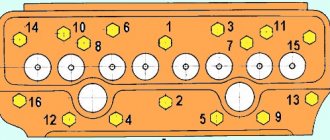
Location of fittings on the head of the fuel pump ND-22/6B4 of the SMD-60 engine on the T-150 tractor.
ATTENTION! Incorrect connection of high-pressure pipes, as well as installation of the pump not in the compression stroke of the first cylinder, leads to burning of the edges of the piston combustion chamber and engine failure.
Turbocharger TKP-11H-1 for SMD-62 engine
The turbocharger installed on this diesel engine directs the energy of the exhaust gases to pressurize air into the cylinders. By increasing the weight of air entering the engine cylinders, the turbocharger promotes the combustion of increased doses of diesel fuel and provides an increase in engine power.
This turbocharger consists of a centrifugal single-stage compressor and a centripetal radial turbine. Its operating principle is that hot exhaust gases from the diesel cylinders go under pressure into the gas turbine chamber. From the chamber, they, expanding, go to the blades of the turbine impeller and cause it to rotate. The rotation of the turbine impeller is transmitted through the shaft to the centrifugal compressor wheel, which is located at the other end of the shaft.
The centrifugal compressor draws air through the air cleaner, compresses it and pressurizes it into the intake manifold.
Tuning
Motors used to power agricultural machines and mechanisms are not subject to tuning. Developed for specific operating conditions, they are, as a rule, perfectly balanced and interference with their design does not lead to positive results.
Families of such engines are presented by manufacturers in the form of wide lines with different power levels. At the same time, they are installed on certain types of special equipment, from which consumers choose those that most fully meet their requirements.
Lubrication system
The SMD-62 engine lubrication system includes:
- oil pump,
- pre-oil pump,
- oil filter centrifuge,
- turbocharger oil filter.
The lubrication system uninterruptedly supplies oil to the rubbing parts of the engine to reduce friction and wear, as well as to remove heat and wear elements from them. Also, a layer of lubricant on the surface of the liner, rings and piston provides a better seal between the liner and the piston.
Engine cooling system SMD-62
The SMD-62 engine has a closed liquid forced cooling system. Its main units are a water pump with a fan and a radiator. Also, starting in 1976, for the purpose of automatic temperature control, 2 TS-107 thermostats were installed on each engine of this model. When the starting engine is turned on, when the engine crankshaft is not yet rotating, a local thermosyphon circulation of water occurs in the cooling system, ensuring rapid heating of the starting engine.
After starting the engine (which is important in cold weather), until the coolant warms up to 80 degrees, the main thermostat valves are closed. Because of this, the liquid bypasses the radiator - it goes to the pump and returns to the crankcase. At temperatures above 80°C, the main thermostat valves partially open and coolant begins to partially circulate through the radiator. And when the liquid temperature reaches 90 degrees, the valves open completely, and the entire flow goes through the radiator.
In the cold season, the engine temperature is additionally regulated by a curtain, which is controlled by a chain from the tractor cabin. To regulate the pressure in the radiator, there are steam and air valves in the filler plug. The steam valve is used to remove generated water vapor from the radiator. It opens when the pressure in the radiator increases to O.O5-O.O7 MPa (O.5-O.7 kgf/cm2). The air valve is designed to connect the radiator with the surrounding atmosphere. It opens at a vacuum in the radiator of O,OO1-O,O12 MPa (O,O1-O,12 kgf/cm2).
On SMD-62 diesel engines since 1975, the fan is driven by two belts instead of one. In this regard, the design of the pulleys on the crankshaft, water pump and tension roller was also changed. The belt tension is adjusted by a tension roller. Its bearings are permanently lubricated with grease.
Cost and reviews of the SMD engine
It is worth noting that the cost of these engines is very low. It cannot be compared with imported analogues. All components for these units that may be needed during repairs are also low in cost. It is also worth noting that, despite the long break in the production of these models, there are a lot of spare parts for them and they are not difficult to find, since previously too many of these engines were produced.
However, it is worth noting that their low cost is not for nothing. Reviews about the SMD-21, for example, are not the most pleasant. Despite the fact that major repairs were carried out once a year, the maximum speed was only 80 km/h when driving downhill and the clutch was depressed, and if not depressed, then 60 km/h. The owners also said that vibration in the engine constantly caused everything to spin up. The only plus that stood out from user reviews was fuel consumption, which was only 20 liters per 100 km.
Starting motor P-350 of the SMD-62 motor
To start the SMD-62 diesel engine, a starting device was provided, which consists of a P-Z5O starting motor and a gearbox.
Starting engine - 1-cylinder, carburetor, 2-stroke, with crank-chamber purge. It has a power of 9.94 kW (13.5 hp), with a crankshaft speed of 66.7 rpm (4000 rpm), and is mounted on the diesel flywheel housing flange. The engine is started by the STZ62 starter, or by a manual starting mechanism that duplicates it.
Technical specifications
The technical characteristics of SMD engines are as follows:
- The working volume of the cylinders is 9.15 liters.
- The power of this unit is 160 hp.
- The number of crankshaft rotations reaches 2000 rpm, the nominal minimum value is 800 rpm, and the maximum nominal value is 2180 rpm.
- The number of cylinders in SMD engines is 6.
- The cylinder locations in the engine are V-shaped, with a camber angle of 90 degrees.
- The diameter of each cylinder is 130 mm.
- The piston stroke is 115 mm.
- The cooling system of this motor is water, closed type, and is also equipped with forced ventilation.
- The characteristics of the SMD engine also provide for a combined lubrication system; the starting system is presented in the form of a P-350 starting engine with remote start.
Such engines are installed on such types of tractors as T-150, T-153, T-157.
Other modifications of the SMD-60 diesel engine
In addition to the SMD-62, several more modifications were developed based on the SMD-60 diesel engine and produced in mass production. This
- SMD-64 – for the SK-6 “Kolos” grain harvester of the Taganrog Combine Plant and the KC-6 root harvester of the Ternopil Combine Plant;
- SMD-68 – for skidding tractor – wheeled tractor T-157;
- SMD-68D – for wheeled tractor T-158
- these are models of the Kharkov Tractor Plant named after Sergo Ordzhonikidze, made on the basis of the T-150.
Source