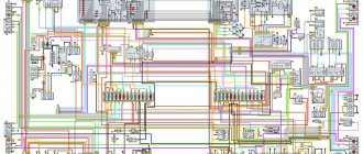
Symbols for the elements of the electrical circuit of the GAZ-3309 car: A8′ - pre-heater; A10 - heater; 81 — oil pressure indicator sensor; 82 — oil pressure alarm sensor; 87 — coolant temperature indicator sensor; 88 — coolant overheat indicator sensor; 812 — fuel level indicator sensor; 819 — air filter clogged indicator sensor; 831 — emergency pressure sensor (1 brake circuit); 832 — emergency pressure sensor (1! brake circuit); 861′ — preheater overheating indicator sensor: 867 — brake fluid level sensor; 897 — pressure sensor (| brake circuit); 898 — pressure sensor (p brake circuit); 899 — emergency piston stroke sensor in the pneumatic booster (1 brake circuit); 8100 — emergency piston stroke sensor in the pneumatic booster, left brake circuit); 8101 — emergency piston stroke sensor in the right pneumatic booster (||brake circuit); 025 — control unit for electric headlight adjustment; E1 — left headlight; E2 - Right headlight; Eb - Front left lamp; Eb - Front right lamp: E9 - left turn signal repeater; E10 — right turn signal repeater; E11 — Front left contour lamp; 812 — Front right contour lamp; E16 — cabin ceiling; E27 - Rear left lamp; E28 — rear right lamp; E29 — reversing lamp; EZ1 - Rear fog lamp; EZZ — Rear left contour lamp; E34 — Rear right contour lamp; E35 - engine compartment light; EZ7 — front left side marker light; E38 — Front right side marker light; E39 — Rear left side marker light; E40 — Rear right side marker light; EbOEbZ - glow plugs; 854′ — glow plug for pre-heater; E/Z - left signaling unit; E84 - right signaling unit; 1:26” — thermal fuse of the pre-heater; 1:41 — fuse box; 1:42 — upper fuse box; 1:43 - lower fuse box; 61 - generator; 6265 - batteries; Н1 — left sound signal; H2 - right sound signal; NC - air pressure drop buzzer; H7 - emergency oil pressure drop alarm; Н8 — coolant overheating indicator; Н9' — preheater overheating indicator; H11 - air filter clogging indicator; H16 - signaling device for turning on the tractor's direction indicators; - H19 - signaling device for critical fuel level; H20 — headlight high beam indicator; NZO - parking brake activation indicator; Н37′ — preheater operation indicator; H39 - ABS fault indicator; H44 — backlight lamp for air pressure level indicator (| brake circuit); H45 — backlight lamp for air pressure level indicator (1! brake circuit); H47 — fuel level indicator illumination lamp; H48 - current indicator illumination lamp; H54 - battery discharge indicator: H56 - insufficient brake fluid level indicator; H62 — front side light lamp; Nbb - speedometer backlight lamp; Nb7 - backlight lamp for temperature level indicator; H68 - backlight lamp for pressure level indicator; H69 — tachometer illumination lamp; H74 - brake signal lamp; H76 - rear side marker lamp; H78 - rear turn signal lamp; NZO - side light signaling device; H96′ - indicator for turning on the glow plug of the pre-heater; H98 - low beam lamp; H100 - high beam lamp; H102 - front turn signal lamp; K1 - additional starter relay; K3 - windshield wiper relay control; K5 - starter blocking relay; K7 - sound signal relay; K8 - brake signal relay; K1O' - pre-heater thermal switch; K11' - relay for turning on the pre-heater spark plug; K12 — turn signal switch; K22′ — preheater pulse generator; K64 - glow plug relay; K71 - rear fog lamp relay; K74 - engine stop solenoid relay; M1 - '- starter; M2 — electric motor of the cabin heater, right; M4 - windshield wiper motor; M5 - windshield washer motor; M7′ — pre-heater electric motor; M8′ - electric motor of the liquid pump of the preheater; M23 — electric motor of the cabin heater, left; M38 - electric drive for left headlight range control; M39 - electric drive for right headlight corrector; mm - engine stop electromagnet; RZ - tachometer; P4 - current indicator: Rb - coolant temperature indicator; P7 - oil pressure indicator; P8 - fuel level indicator; P12 — pressure gauge (| brake circuit); P13 — pressure gauge (|| brake circuit); 01 — mechanical battery switch; 812′ — preheater electric motor resistor; 81 — instrument and starter switch; 35 — hazard warning light switch; 56 — cabin heater switch; 39 — switch for direction indicators, headlights and sound signal; 812 - windshield wiper switch; $18 - rear fog lamp switch; 329 — reverse light switch; 530 — brake light switch; 839 — light switch; 844′ — preheater switch; 845′ — preheater operating mode switch; 873 — cabin heater switch; 8123″ — glow plug switch for pre-heater; 5124 — parking brake warning switch; 8127 — seasonal adjustment switch; 5132 - glow plug switch; X4 - portable lamp socket; KhZE - 1-pin block; X40 - socket block; U47' - electromagnetic fuel pump for pre-heater
Auto repair manual for GAZ 3308 in electronic form. The manual will always be at hand during car maintenance and repair; to do this, just download it for free to your tablet or phone in pdf format.
Before using the car manual, check the year of manufacture and engine of the car.
Russian language
Format: pdf
File size: 211.6 Mb
e-book in pdf format
- Warning
- Loading
Please remember that your vehicle may not include all the features described in the manual. The repair manual may contain discrepancies with the description of your specific vehicle, and you may also find descriptions of options and equipment that are not on your vehicle.
What will you find in the GAZ 3308 repair book?
Detailed information about the device of the car.
Algorithm for identifying faults, a system of daily and periodic checks, reference information on self-diagnosis of GAZ 3308.
Instructions for timely vehicle maintenance.
Step-by-step guide for self-repair of GAZ 3308.
Description of the book
Repair book for GAZ 3308
Operation of any GAZ 3308 vehicle is impossible without knowledge of its structure, maintenance and repair features. It doesn’t matter who will carry out the necessary work - every driver is simply obliged to know the basic maintenance and troubleshooting procedures.
The GAZ 3308 repair book contains all the necessary information that will help the owner understand the structure of the car, teach how to properly care for the car, timely maintenance and proper repairs.
The GAZ 3308 repair manual is divided into chapters: Vehicle design (describes general information and vehicle specifications); Operating instructions (preparation for departure, recommendations for traffic safety); Malfunctions along the way (tips to help you in case of an unexpected breakdown on the road); Maintenance (detailed recommendations for all maintenance procedures); Repair instructions (engine, transmission, chassis, steering, brake system, and also includes assembly and disassembly work necessary during the repair process of the GAZ 3308); Electrical equipment (detailed manual for diagnosing and troubleshooting, the main units are described separately and detailed electrical diagrams of the GAZ 3308 are given).
Any of the GAZ 3308 repair procedures is given according to the principle from simple to complex: from simple maintenance operations, adjustments, replacement of parts, to global repairs with assembly and disassembly work.
All materials in the book are based on specific experience gained in the process of complete disassembly and assembly of the GAZ 3308 by highly qualified auto mechanics.
The book “GAZ-3308, 33081. Maintenance, operation, repair, electrical circuits” is necessary so that diagnostics and repairs of the GAZ 3308 can be done professionally and quickly, even by the owner of the car who still has little practical experience.
You can download the GAZ 3308 repair manual for free in pdf format. You just need to download it to your phone or tablet and you can use it in any situation on the road.
We'll check on the spot
In fact, both the installation of the new engine itself and the modernization of products required the factory workers to make a number of design changes. The updated Sadko has a strengthened frame, new double-cone synchronizers in the gearbox, different driveshaft crosspieces, and there are a lot of small innovations. Polyamide pipelines of the fuel system, new power unit supports, the design of the steering mechanism was measured, and a heated filter separator.
The new engine, since it is equipped with an electronic control unit, required, in turn, electronic drives for the accelerator pedal, speedometer and tachometer. The first thing you notice when you get into the cab is that the odometer now has no wheels. And for some reason, once again today I felt warm and good: an old, familiar, one might say, dear car, but in a new interpretation. But the changes did not affect the well-known bent gearshift lever, the steering column is still not adjustable, and the wiring and contacts in some places look like they were made by a schoolboy in a labor class, and even then with a C grade.
It’s okay, everything can be brought to mind, it would be for the sake of it - I have no aversion to this car, even if I flog it! And I am perfectly aware that if it were any, the most shabby “bourgeois,” I would not forgive him for anything like that! And rightly so! The amount that its manufacturers are asking for the new Sadko is a textbook example of the relationship between price and no, not quality, but rather a combination of qualities, a set of capabilities, consumer and operational properties. Now let's go! On the landfill road, virgin lands, country roads, snow, ice, asphalt.
Scheme GAZ 3309 diesel
Scheme GAZ 3309 diesel four-stroke, turbocharged, liquid-cooled, with a displacement of 4.75 liters and a power of 147 hp. The diesel engine is equipped with a high-pressure fuel pump with a booster pump.
Scheme GAZ 3309 Diesel D-245 is a 4-stroke piston four-cylinder internal combustion engine with an in-line vertical cylinder arrangement, direct injection of diesel fuel and compression ignition.
The main elements of the GAZ 3309 diesel engine are: cylinder block, cylinder head, pistons, connecting rods, crankshaft and flywheel.
To ensure high technical and economic indicators of the diesel engine, turbocharging with intermediate cooling of the charge air is used in the intake system.
The use of a turbocharger with adjustable boost pressure in the supercharging device allows for improved throttle response on a diesel engine, provided by increased torque values at low crankshaft speeds.
brake system diagram gas 3309
Generator circuit GAZ 3309
Generator circuit 5101.3701 GAZ 3309 with diodes and voltage regulator YA120M1. Old style diode bridge BPV 56-65-02 with two wires. The GAZ 3309 generator consists of a housing, stator winding, rotor, diode bridge and built-in voltage regulator.
The GAZ 3309 generator circuit, thanks to a system with additional diodes, allows you to receive current from the output of additional diodes, and not from the generator output as before. Thanks to this scheme, battery discharge through the generator excitation winding is practically reduced to zero. The current in a similar circuit of the GAZ 3309 generator flows only inside the generator itself, without using external circuits and the ignition switch (except for the initial excitation).
Verification methods
Given the external similarity of the electrical equipment, the automaker reasonably assumed the possibility of errors when servicing the car independently, the price of which was high. Therefore, I provided automatic protection of elements from accidental short circuits:
- The generator excitation winding circuit is protected using a protection relay, as well as a separating diode;
- While the engine and generator are running, the relay contacts are open;
- If a wire breaks or short circuits, the current flowing through the relay winding will increase;
- The opposing winding will create a magnetic field, the core will retract and open the relay contacts (see also the VAZ 2101 wiring diagram).
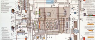
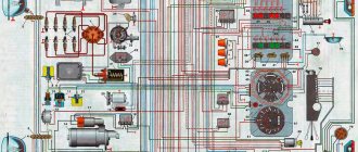
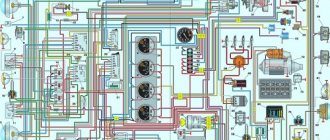
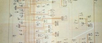
Color scheme GAZ 3309
The GAZ 3309 color diagram allows you to quickly and clearly read the electrical wiring diagram of the GAZ 3309 car.
- Side turn signal mounted on the right front fender.
- Front marker light (right).
- Right headlight.
- Connection strip.
- Left headlight.
- Low beam lamp installed in the headlight.
- High beam lamp.
- Side light bulb.
- Front marker light (left).
- Direction indicator lamp installed in the front position lamp.
- Side turn signal located on the left front fender.
- Coil.
- Spark pulse distributor.
- Candle.
- An additional resistor to eliminate radio interference in the spark plug tip.
- Starter.
- Battery.
- Starter control relay.
- Battery power switch.
- Indicator lamp for activated high beam headlights.
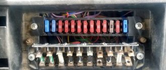
- Upper section of the interior fuse box.
- Klaxon.
- Gas valve solenoid. Installed only on trucks equipped with gas cylinder equipment.
- Electromagnetic element of the gasoline supply valve, used on vehicles with a combined fuel system (gas-gasoline).
- Fuel type switch.
- Ignition system switch.
- An auxiliary relay that turns on the starter.
- Central lighting mode switch.
- Generator.
- Control key for rear fog lamp operation.
- Plug connector.
- Control resistance.
- Additional fuse for autonomous heater. The unit is installed as a separate order.
- An electric motor that ensures the functioning of an independent engine heating system.
- Instrument cluster illumination lamp.
- Cabin lighting.
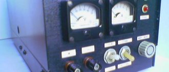
- Ammeter.
- Voltage regulator unit in the on-board network.
- Autonomous heater control panel.
- Fuel ignition switch in the heater boiler.
- Autonomous operating mode switch.
- An electromagnetic valve that regulates the supply of gasoline to the combustion chamber of an autonomous heater.
- Gas system pressure gauge.
- Coolant temperature sensor.
- Sensor for turning on a lamp warning of overheating of the power plant.
- A sensor that transmits information about the pressure in the lubrication system.
- A separate device that measures critically low pressure in oil lines.
- Ignition switch with built-in contact group.
- Bottom of the interior fuse box.
- A socket designed to connect additional equipment (portable lamp, etc.).
- Alarm control button.
- Starter heater spark plug.
- Second gas system pressure gauge.
- Gasoline level indicator in the fuel tank.
- A control device that displays engine temperature.
- Lubrication system pressure gauge.
- Electric motor to drive the windshield wiper blades.
- Control relay for the glass cleaning system.
- Washer pump drive motor.
- The steering column switch is responsible for selecting the operating modes of the headlights and direction indicators.
- An additional device is used to provide warning sounds.
- Key for turning on increased fan speed for the standard cabin heating system.
- A similar unit for lower frequency.
- Brake light limit switch.
- Toggle switch for determining the fuel level in different tanks.
- Steering column switch for windshield wiper operating modes.
- A separate indicator displaying the operation of turn signals on towed equipment.
- Indicator lamp for direction indicators on the tractor. When using a single vehicle, only this lamp is active.
- Indicator for turning on side lighting.
- Indicator of the state of the drive of the second circuit of the brake system.
- A similar lamp for the first circuit.
- Indicator lamp for activation of the parking brake and malfunctions in the main circuits.
- Signal unit housing.
- Limit switch for determining the position of the parking brake handle.
- Heater motor on the right side of the cab.
- A similar unit for the left side.
- Measuring fluid level sensor in the hydraulic brake drive.
- A sensor that measures the degree of vacuum in the first brake circuit.
- A similar device for the second circuit.
- Sensor for measuring the amount of fuel in the main tank.
- Switch plate.
- Limit switch in the crankcase box, used to connect the reverse light.
- A contact relay that provides operation of the hazard warning lights and direction indicators.
- Fuel level measurement sensor in the additional tank.
- Back light.
- Socket for connecting electrical equipment on the trailer.
- Fog light mounted on the rear of the truck.
- Reverse lamp.
- Brake warning lamp.
- Dimensional signal.
- Rear direction indicator.
Scheme of autonomous cabin heater GAZ 3309
The circuit diagram of an autonomous heater for a GAZ 3309 cab consists of an air intake, a heater radiator, two fans and a coolant. The autonomous heater maintains the specified temperature conditions in the GAZ 3309 cabin, as well as for blowing the windshield and door windows.
Diagram of the autonomous cabin heater GAZ 3309:
- 1 and 7 – nozzles for heated side windows
- 2 and 6 – windshield heating pipes
- 3 – air intake box
- 4 – air intake duct damper
- 5 – heater radiator
- 8 and 12 distributors
- 9 – radiator casing
- 10 damper
- 11 lever
- 13 facing
- 14 – air intake damper control handle
- 15 – heater tap control handle
GAZ 3309 GAZ 3309 diesel dump truck
GAZ-3307 is a medium-tonnage truck, produced since 1990 at the Gorky Automobile Plant. The machine is quite reliable, but sometimes some malfunctions occur, including electrical equipment for gas 3307. Any of its elements can fail. To find and fix problems, use the car's electrical diagram. Anyone can learn to read and understand it.
Truck GAZ 3307
Description
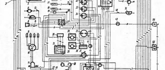
The electrical circuit of the GAZ-3307 is a drawing on which there are pictograms of the electrical elements of the car, connected to each other by switching lines indicating wires. The equipment is located approximately where it is when looking at the machine from above, although deviations (sometimes significant) are possible. On the left are usually the headlights and sidelights of the front of the car, to the right are the electrical equipment of the engine compartment, interior and rear lights.
Electrical circuits are available in black and white and color. The latter are easier to read; the colors of the lines are the same as those of the corresponding wires. Often electrical components are shown in the form of pictures (instrument panel, starter, headlights, etc.), they can be recognized without looking at the “legend” (the explanatory text under the diagram or on the side of it). An example of a color wiring diagram is shown below.
Black and white diagrams are usually more detailed and often provide additional information (for example, thin lines show current conductors inside devices). The color of the wires is indicated by a letter (H - black, Z - green, and so on). The numbers (2; 0.5 and others) in the breaks in the switching lines indicate the cross-sectional area of the wire in square millimeters. There are standard pictograms and conventional images of certain devices. Next to them (sometimes on a callout) is a number or letter with numbers. This is the designation of the element whose name is indicated in the “legend”.
Troubleshooting
If any device fails, using an electrical circuit it is easy to check whether it has failed or whether the electrical circuit has been interrupted somewhere.
Power supply circuit for a GZ-3307 car. To do this, you will need a test light with wires and clamps or a tester turned on in voltmeter mode (voltage detection). We connect one clamp of the light bulb (tester) to the input contact of the element being tested, the other to the “ground”, that is, the negative terminal of the battery or any part of the frame, body or engine (cleaned of paint).
...and beyond
We get stuck, we shake, but we crawl, and we can’t reduce the speed - there won’t be enough torque, and if we add more, we slip, but still, even if it’s just a gram or a millimeter, we’re still crawling. And why were we given this hill? Oh, yes, testing and photography... If you slow down, you’ll be afraid of stalling, and then you’ll definitely never move again without outside help, if you add, you’ll skid in vain, or worse, you’ll dig in. Where is the golden mean? Go and look... At this very moment, the new modern diesel engine with electronic control shows itself in all its glory: attempts to stall begin only when the speed approaches 500 min -1, and you can safely spin it up to slightly clear the tread of loose snow to the maximum permissible 2300 min -1, and only after a good forty minutes of such cruel cycles, when the transfer case was switched on in a low range, with complete blocking, the warning lamp of the starting overheating of the coolant blinked a couple of times. But as soon as you reduce the load a little and add heating, the temperature calmly drops to a safe 80º. Here it is, the treasured “hill”. Now the long-awaited photo shoot is taking place, and the car is on a smoke break. After such a “special stage”, out of old habit, I want to check the tightness of all threaded connections and the condition of other fasteners. This is our own gas car! But now it no longer stalls at idle, does not choke from lack of torque, does not throw black soot into the exhaust pipe and does not consume tons of expensive fuel. Well done keep it up!
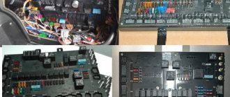
GAZ 3309 starter: where is it located, how to remove, replacement
GAZ 3309 is a popular truck that was produced in the USSR; later, another modification of the vehicle began to be produced in Russia; its main difference was that the gasoline engine was replaced with a diesel engine, which is labeled as MMZ D-245.7E4.
It has several modifications, the most popular version is an engine that produces 125 “horses” and complies with the Euro-4 environmental class. It is worth noting that there is another diesel engine, but it is less common.
The car is still in production, despite all its modern competitors, and the GAZ 3309 is still a frequent participant in road traffic in our country. The whole secret is the simplicity of the device and the reliability of spare parts. Of course, any mechanism has its own resource, and the GAZ 3309 also has breakdowns. Let's touch on the issue of the starter of this car in more detail.
Types of faults
Sometimes people mistakenly blame the starter, but in the end it turns out that it is not the fault. The thing is that the starter works in conjunction with other systems and components of the car (starting-charging circuit).
In general, all starter failures can be divided into two large groups:
- Mechanical faults,
- Electrical breakdowns.
Each group has its own nuances, so it is worth considering them in detail.
Electrical breakdowns
If the starter does not turn the engine at all or does so very slowly (with insufficient power to start the engine), you must first check the electrical circuit. This must be done from the battery to the starter.
The rechargeable battery (AB) should be given special attention in this matter. Need to check:
- Charge (the battery must be fully charged),
- Ground contacts (they must be reliable and well secured),
- Wire from the solenoid relay terminal (integrity and good contact),
- Wire from the battery to the starter (integrity and good contact),
- Contact group of the ignition switch (serviceability).
The above-mentioned problems occur when it is possible to turn the key in the ignition switch, but there is no activation of the retractor relay (the armature does not rotate) or there is a break in the winding of the traction relay, as well as a short circuit of the turns or to ground. In addition, slow turning of the flywheel may indicate problems with the electrical part of the starter.
If there are no visible visual faults with the starter, then you need to dismantle it in order to examine it more carefully. Thus, it is possible to determine whether the commutator is burning or to find a short circuit in its plate.
But the experience of studying the issue suggests that the most common electrical malfunction is wear or hanging of the brushes.
Now we can distinguish three main breakdowns from this category of faults:
- Poor contact between the brushes and the commutator,
- Broken traction relay,
- Armature commutator wear.
Mechanical problems
If the starter works, but the engine does not start, then the problem is from this category. In this case, you need to check the following details:
- Overrunning clutch lever,
- Clutch ring,
- buffer spring,
- Flywheel crown.
When the starter is running, the car engine does not start for the following reasons:
- Clutch slipping (failure of the release lever, its jumping off the axis, wear of the clutch drive ring or wear of the buffer spring). Defective parts should be replaced.
- If a grinding noise is heard during startup, this is wear on the flywheel ring teeth. The gear travel should be checked for any blockages, and the condition of the buffer spring should be checked for functionality.
- If a very strange noise is heard, then you should check from the “pit” and engine compartment for such faults as wear of the bearing sleeve, journals on the armature shaft, loosening of the starter mounting bolts and damage to the teeth. In addition, the pole inside the starter may become loose.
Diesel problems
Let's leave the topic of owners, shareholders, holdings, marketing and finance today. It’s just that now the production program of the GAZ plant from Nizhny Novgorod includes an all-wheel drive truck model GAZ-33088 “Sadko” with a new modern diesel engine model YaMZ-534 from the ancient Russian city of Yaroslavl. It was this version of the long-lived medium-tonnage conveyor vehicle, which received the index 33088, that I was invited to test at the factory test site in the vicinity of Nizhny. Of course, I happily agreed.
At the beginning of their careers, few of the road transport workers of my generation thought that foreign rolling stock would dominate modern road transportation. And it is all the more interesting to return to the roots again, to get acquainted again with cars that have survived the harsh conditions of the Russian market, have been produced for many years, but are still in demand today.
Attempts to equip off-road medium-duty trucks with a compact and economical diesel engine from GAZ OJSC have been made more than once. However, until recently, the only workable option remained the notorious obsolete Minsk D-245 engine, which had many complaints. The Yaroslavl motor offered today was created not under license, but from scratch, in collaboration with the Austrian engineering company AVL. The characteristics of power, toxicity and torque (134 hp at 2300 min -1 ; 417 N∙m in the range 1200–2100 min -1 ) are quite at the modern level, the increase in price of the base car compared to the Minsk power plant is no more than 50,000 rub. Very tempting, but how efficient is it?
Malfunctions of the ignition system of GAZ-3307
For example, let's find a fault in the ignition system, which is one of the most important in a car. Failure or poor performance of any of the elements is a serious problem, especially while traveling. The engine stalls or runs intermittently, it is advisable to quickly find and eliminate the cause.
First, make sure that the problem is in the ignition system (there may also be a fuel supply malfunction). Remove the wire from any spark plug and bring its end to ground at a distance of 6–9 mm. When the engine is cranked by the starter, a spark should appear. Be careful, the circuit is under high voltage; you should work with rubber gloves or use improvised objects that do not conduct current, for example, wooden ones, holding the wire with their help. If there is no spark, remove the central wire from the distributor cover and check it in the same way as a spark plug.
There is a spark - the problem is in the breaker-distributor (item 3), if not - let's continue the search. Make sure that current is supplied to the induction coil terminal (item 5). To do this, connect the clamps of the control light to the corresponding connector and ground: the light should light up (with the ignition on). Similarly, check the output of the switch (item 4) with the + sign. If there is current, connect a light bulb (with a power of no more than 3 W) to the short-circuit terminal and ground. It should flash when the starter is turned on. If this happens, the ignition coil is faulty.
If the light is on continuously or does not light up, the switch is faulty (unfortunately, a typical problem on the GAZ-3307).
If current is not supplied to the coil, we determine according to the diagram the next element in the circuit - the ignition switch (item 9). Both contacts must be energized (with the ignition on); if only the incoming one is energized, then the lock is faulty.
The next element in the circuit is the fuse (item 7). It must be checked if there is no voltage at the incoming terminal of the ignition switch. If a fuse is blown, try to find the cause before replacing it. Most likely, this is a short circuit; its sign is a dark spot at the breakdown site. The wire must be cleaned, the burnt ends connected (if necessary) and carefully insulated.
On road…
Before the assault on the virgin snow, “Sadko” and I decided to take a ride along a straight and deserted winter highway.
- My friend, even twenty years ago I remember your hood lifting up at speed, diagonal swing, yaw, transmission noise.
– Nothing, but the speeds are now switched on much better, especially low ones, without the characteristic “belching”; and the maximum and, mind you, artificially limited to 85 km/h is now not an example of correct adjustment of the ignition and power supply of the huge ZMZ, but just the usual capability of a compact four-cylinder “in-line” from Yaroslavl. And you can forget about strong vibration.
This is my dialogue with the “lawn” on the eve of an off-road start, and at the very end of winter, when the snow is hard and dense, the depth of cover is the maximum for the season, and skeptics always talk about utopia on the eve of their usual spring aggravation...
conclusions
We hope that in this material we were able to provide a detailed explanation of the features of the car. And the video in this article and detailed electrical diagrams will allow GAZ 3307 owners to independently detect faults in electrical circuits and restore their operating parameters (see also GAZ 3110 wiring diagram).
A collection of electrical circuits for various modifications of domestically produced GAZ cars. The collection contains wiring diagrams for such models as GAZ 3110, GAZ 3307, GAZ 31105, GAZ 2217 and other cars. Click on the diagram to enlarge and download it to your computer.
Electrical diagram Gas 21
1 — sidelight; 2 - headlight; 3 — connecting panel; 4 — spark plug; 5 - suppressive resistance; 6 — sensor for the warning lamp of the coolant temperature in the radiator; 7 — sound signals; 8 — signal switch; 9 — signal activation relay; 10 — engine compartment lamp; 11 — heater motor switch; 12 — heater electric motor; 13 — wiper motor switch; 14 — electric motor of the windshield wiper; 15 — engine coolant temperature indicator sensor; 14 — fuse block; 17 — plug socket; 18 — power supply and low-frequency radio amplifier; 19 — control lamp for coolant temperature in the radiator; 20 - loudspeaker; 21 — hours; 22 — cigarette lighter; 23 — ignition and starter switch; 24 — radio receiver; 25 — instrument cluster; 26 — instrument lighting lamp; 27 — door lamp switch; 28 — lamp Gas-21; 29 — manual lamp switch; 30 — rear light; 31 — license plate light; 32 — trunk lighting; 33 — fuel level indicator sensor; 34 — handbrake warning lamp switch; 35 — handbrake warning lamp; 36 - lighting circuit fuse; 37 — direction indicator switch; 38 — light switch “Stop”; 39 — central light switch; 40 — control lamp for high beam headlights; 41 — turn signal indicator lamp; 42 — turn signal switch; 43 — starter; 44 - battery; 45 — foot light switch; 44 - additional starter relay; 47 — reverse light switch; 48 — relay regulator; 49 — engine oil pressure indicator sensor; 50 - generator; 51 — ignition coil; 52 - ignition distributor Gas 21.
Wiring diagram GAZ 2705
1 – front direction indicator; 2 – headlight (side beam, low beam and main beam); 3 – spark plug GAZ 2705; 4 – interference suppression resistance; 5 – ignition distributor sensor; 6 – lampshade; 7 – engine compartment lamp; 8 – headlight lamp; 9 – side light lamp; 10 – windshield washer motor; 11 – turn signal repeater; 12 – voltage regulator: 13 – transistor switch; 14 – ignition coil; 15 – rear fog lamp switch; 16 – lower fuse block; 17 - sound signal; 18 – turn signal repeater; 19 – generator; 20 – fuse block; 21 – starter relay; 22 – additional resistor of the ignition coil; 23 – lighting switch; 24 – starter: 25 – ignition switch unloading relay; 26 – solenoid valve; 27 – EPHH system switch; 28 – EPHH control unit: 29 – battery; 30 – ignition switch; 31 – hand brake breaker; 32 – parking brake switch; 33-brake fault indicator sensor; 34 – coolant overheat indicator sensor; 35 – coolant temperature indicator sensor; 36 – oil pressure indicator sensor; 37 – emergency oil pressure indicator sensor; 38 – direction indicator switch; 39 – upper fuse block; 40 – driver signal buzzer; 41 – portable lamp socket; 42 – platform lamp; 43 – driver signal switch; 44 – hazard warning light switch; 45 – turn signal switch; 46 – instrument cluster; 47 – fuel remaining indicator; 48 – voltage indicator; 49 – fuel level indicator; 50 – coolant overheat indicator; 51 – indicator of malfunction of service brakes and activation of the parking brake; 52 – turn signal indicator; 53 – backup signaling device GAZ 2705; 54 – backup signaling device; 55 – high beam headlight indicator; 56 – side light indicator; 57 – backlight lamp; 58 – emergency oil pressure indicator; 59 – oil pressure indicator; 60 – coolant temperature indicator; 61 – tachometer; 62 – windshield wiper control relay; 63 – heater motor switch; 64 – cigarette lighter; 65 – brake signal switch; 66 – high-speed light switch; 67 – windshield wiper motor; 68 – wiper switch; 69 – heater motor resistor; 70 – heater electric motor; 71 – radio receiver; 72 – fuel level indicator sensor in the left tank; 73 - additional heater; 74- additional heater resistor*; 75 - auxiliary heater switch*; 76- rear light; 77 - fog lamp**; 78- license plate lamps; 79- brake signal lamp; 80 - tail light lamp; 81 - rear turn signal lamp; 82 - rear running light lamp; 83 - fog light lamp; 84- heating system electric pump switch*; 85 - electric pump of the heating system*.
Auto repair manual for GAZ 3308 in electronic form. The manual will always be at hand during car maintenance and repair; to do this, just download it for free to your tablet or phone in pdf format.
Before using the car manual, check the year of manufacture and engine of the car.
Russian language
Format: pdf
File size: 211.6 Mb
e-book in pdf format
- Warning
- Loading
Please remember that your vehicle may not include all the features described in the manual. The repair manual may contain discrepancies with the description of your specific vehicle, and you may also find descriptions of options and equipment that are not on your vehicle.
What will you find in the GAZ 3308 repair book?
Detailed information about the device of the car.
Algorithm for identifying faults, a system of daily and periodic checks, reference information on self-diagnosis of GAZ 3308.
Instructions for timely vehicle maintenance.
Step-by-step guide for self-repair of GAZ 3308.
Controls
The location of the controls is shown in Fig.
5.1. Rice. 5.1. Controls:
1 and 8 — nozzles for blowing the cabin glass;
2 — instrument panel;
3 - lever for switching direction indicators, headlights and sound signal. The lever has six fixed positions - I, II, III, IV, V and VI and four non-fixed positions “A” (Fig. 5.2 and 5.3).
* On some vehicles, the sound signal is turned on by the windshield wiper and washer switch (see Fig. 5.5).
If the switch lever is in position I and the central light switch is in position II, then the low beam headlights are on. By moving the lever to position II, the high beam headlights come on and the blue indicator light comes on.
When the switch lever is repeatedly moved from position I towards you along the steering column (non-locking position), the high beam headlights are signaled.
Rice. 5.2. Positions of the turn signal and headlight switch lever (with sound signal)
Rice. 5.3. Turn signal and headlight switch positions (without horn)
When you press the lever button (from any position) along the axis, a sound signal* is activated (without locking) - see fig. 5.2.
When the lever is moved from position I or II up to position VI or IV (right turn) or down to position V or III (left turn), the direction indicators turn on and a green flashing warning light comes on on the instrument panel. The switch has an automatic device for returning the lever to position I or II after the end of the turn. To briefly turn on the direction indicators, the switch lever must be moved to the corresponding non-fixed position “A”. When released, the lever returns to position I or II.
4 — steering wheel.
5 — switch lever for windshield wiper, windshield washer and horn*. When the lever is in position (Fig. 5.4): O - the windshield wiper is off; I — low speed windshield wiper is on; II — high speed windshield wiper is on; III - intermittent operation of the windshield wiper is turned on.
* On some vehicles, the sound signal is turned on by the windshield wiper and washer switch (see Fig. 5.5).
Rice. 5.4. Windshield wiper and washer switch positions (without horn)
Rice. 5.5. Windshield wiper and washer switch positions (with horn*)
When the lever is in position (Fig. 5.5):
0 — windshield wiper off; I — intermittent operation of the windshield wiper is on; II — low speed windshield wiper is on; III - high speed windshield wiper is on.
If the switch does not have a horn switch (Fig. 5.4), then moving the lever towards you (in the direction of the arrow) from position 0 briefly turns on the washer and wiper.
If the switch is equipped with a sound signal switch* (Fig. 5.5), then to turn on the washer and wiper for a short time, the switch lever must be moved from position 0 away from you (in the direction of the arrow “A”), and to turn on the sound signal* the lever must be moved (from any position) toward you (in the direction of arrow “B”).
The washer can be turned on from all positions of the lever.
* On some cars, the sound signal is turned on by the turn signal and headlight switch (see Fig. 5.2).
The windshield wiper only works when the ignition is on.
6 - removable fuse block panel. On the inside of the panel there are signs indicating the consumers protected by these fuses.
7 - glove box.
9 — knob for the control unit for electric headlight adjustment, depending on the vehicle load (Fig. 5.6).
Rice. 5.6. Handle of the headlight range control unit
When the corrector knob is in position:
0 – corresponds to an unloaded vehicle;
1 - corresponds to a fully loaded vehicle.
10 — control knob for air supply to the main heater. When the handle is in the upper position, only outside air enters the heater; when in the lower position, air from the cabin enters. At any intermediate position of the handle, a mixture of outside air and air from the cabin enters the heater.
11 — control knob for the main heater tap. When the handle is in the upper position, coolant from the engine cooling system flows into the cab heater radiator.
12 - battery switch.
13 — front axle activation lever.
14 — transfer case lever.
15 — gear lever.
The diagram of the positions of the gearbox and transfer case control levers is shown in Fig. 5.7.
16 — valve handle for controlling the tire pressure regulation system.
17 — parking brake lever.
18 — handle for manual control of the throttle valves (GAZ-3308).
Rice. 5.7. Lever position diagram:
A — front axle activation (I — off, II — on); B — transfer case (I — reduction gear is engaged, II — direct transmission is engaged); C - gearboxes
19 — push-button switch for starting glow plugs (for GAZ-33081 vehicles).
20 — switch for electrical equipment, starter and anti-theft device (GAZ-33081); — ignition switch, starter and anti-theft device (GAZ-3308).
Rice. 5.8. Key switch positions
The switch key has four positions (Fig. 5.8):
I - electrical equipment is turned on (GAZ-33081); ignition is on (GAZ-3308);
II - electrical equipment is turned on - GAZ-33081 (ignition is on - GAZ-3308) and starter;
III - electrical equipment is turned off - GAZ-33081 (ignition is turned off - GAZ-3308) and the anti-theft device is turned on when the key is removed. To turn off the anti-theft device, insert the key and, slightly rocking the steering wheel left and right, turn the key to position 0.
When turning off the devices - GAZ-33081 (ignition - GAZ-3308), turn the key from position I to the fixed position 0. To avoid failure of the contact part of the device switch, do not leave the key in an intermediate position.
21 — fuel supply control pedal.
22 — brake pedal.
23 — clutch pedal.
24 — handle for manual control of fuel supply (GAZ-33081); — air damper thrust handle (GAZ-3308).
25 — alarm switch. When the position is on, the direction indicator lamps and the indicator light (red) inside the switch button light up simultaneously in a flashing mode.
26 — radiator shutter control handle (GAZ-3308).
27 — hood lock drive handle.
28 - plug socket.
the GAZ-3308
car is shown in Fig. 5.9.
Rice. 5.9. Instrument panel of the GAZ-3308 car:
1 - indicator (red) of an emergency drop in oil pressure and clogged oil filter. Lights up at an oil pressure of 40–80 kPa (0.4–0.8 kgf/cm2).