Cars tend to break down and require periodic maintenance, like any equipment. Access to the lower part in garage conditions is often impossible due to the lack of a lifting device. Having all the necessary tools, a lift equipped and ready for work, it is possible to replace the consumables of the chassis, transmission, and engine. Despite the fact that the device is in demand when repairing cars with your own hands, purchasing it for use for your own needs is very expensive. Maintenance can be performed no more than twice a year, so it is better to make units and components yourself.
What types of lifts are there?
Lifts come in various designs, differing in the method of lifting the car and the type of drive. For vehicle repairs, three types of drives are mainly used:
- chain mechanisms;
- screw;
- hydraulic systems.
The method of lifting the car plays an important role in the design; a garage lift can be a fork, scissor, or platform design. The most popular are fork screw units, the basis of which is a long threaded shaft made of tool steel. The parts of the unit are able to withstand the load of an average car; it is almost impossible to make the mechanism with your own hands, due to the complex design of the forks.
Types of lifts for car repairs
The easiest way to make a platform lift with your own hands is using a screw mechanism.
Parallel beams attached to the mechanism are capable of lifting a car weighing up to 3 tons.
Types of lifts
Before installing a car gearbox lift on a pit in the garage, we study its main varieties in more detail. This will help you figure out what a pit lift can be like.
By drive type
Jacks for lifting cars differ in the type of drive that is installed in them. There are two main models in this classification:
- hydraulic jack;
- devices with manual mechanical drives.
Experts advise using hydraulic models, as they are more efficient. However, it is not easy to make such a device yourself, and that is why many people make manual car lifts.
By type of lifts
Another distinctive feature of car jacks is the type of lift used in them:
- Screw. To install such equipment, use two durable racks in which special screws are installed. They are responsible for raising and lowering the vehicle. The operation of the installed screws is controlled by an electric motor.
- Mini. In the manufacture of such models, hydraulic or mechanical drives are used. A special feature of the equipment is its small size. Therefore, mini-lifts are not used to lift freight vehicles.
Electromechanical Engineering
Some models use different electromechanical technology. Based on this, car lifts are produced:
- Single post. Experienced motorists advise using such models in small garages, as they are compact. They consist of an electric motor, a movable carriage, and a vertical support.
- Scissor. Scissor car lifts can be mobile or stationary. They are equipped with a strong frame for attaching hinges and a compressor device.
By number of plungers
Based on the number of plungers, multi-plunger, double-plunger and single-plunger models are distinguished. In models with several plungers, a special traverse is installed, which is responsible for the efficiency of the equipment.
Choosing a design
To make a vehicle lifting unit with your own hands, it is important to familiarize yourself with the designs on the market. The cost of finished equipment can be equal to the price of a car. In auto repair shops you can find the most common option - a screw two-post jack; the design can be made with a hydraulic or electric drive. The structure can be made using additional beams, depending on the expected loads. A scissor lift has a platform and is driven by a scissor-like mechanism. A homemade lift of this type is driven by mechanical force and is lifted by a hydraulic drive connected to an electric motor. Before making such structures, it is important not to forget about safety precautions. During operation, parts may spontaneously fall, which will lead to irreversible consequences. A homemade car lift must be made with a reserve of aggregate power; when using it, it is important to know the mass of the element being lifted.
In emergency situations with a garage lift, locking mechanisms allow you to hold the car. To avoid critical moments, it is necessary to check the condition of the electric motor and hoses. The main problem of making a screw lift with your own hands is the complexity of assembly and manufacturing of the mechanism. Hydraulic parts are expensive, purchasing a new design is impractical.
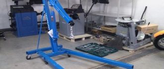
For garage use, a modification of the mechanism is suitable that allows you to lift the car from a certain side. With your own hands, you can make a hydraulic lift that lifts a car at an angle of up to 60 degrees; this design is called a tipper.
Hydraulic garage crane drive
There are several types of hydraulic drive:
- with hydraulic cylinders;
- with hydraulic cylinders and manual winches.
When the operator increases the pressure level in the cylindrical block, the oil fluid acts on the piston part, pushing out the telescopic rod, at which time the boom equipment rises.
Based on the nature of the movement of the output link of the hydraulic power unit, the following types of drives are distinguished:
- Rotational movement. The design of such a mechanism includes a hydraulic motor equipped with a driven link with unlimited rotational movement.
- Forward movement. In this case, a hydraulic cylinder is used with a reciprocating movement of a driven type link (piston rod, plunger).
- Rotary movement. The crane mechanism is equipped with a rotary hydraulic motor, the driven link of which makes a reciprocating movement at an angle of less than 270°.
- Adjustable. In this case, the speed of the output type link can be adjusted by changing the crankshaft speed of the power unit, which activates the high pressure pump.
- With a closed circuit of working fluid circulation. This means that the fuel is returned to the suction hydraulic line of the pump mechanism. This drive is lightweight and provides high rotor speeds without the risk of air getting into the system.
DIY garage lift
For use in the garage, it is possible to make a kit for lifting a car with your own hands. You will need the necessary components, tools and plumbing skills.
A homemade lift is made using the following parts:
- Steel corners measuring 8x8x1 cm, for making a stable structure.
- Worm type gearbox. A new product can be expensive; it is usually selected during disassembly or removed from a non-working mechanism. It is necessary to pay attention to the load capacity, the indicator starts from 350 kg, the transmission force indicator is 60 kg.
- A steel plate with a minimum thickness of 1 cm is removed from old equipment.
- Set of bolts, mounting hook, star-shaped keys.
- Several iron chains with a link diameter of 2 cm or more. Weak chains will not withstand the load, you should pay attention to the quality of the product, some materials can stretch during operation.
- Steel cable, 5 mm thick.
Assembly and installation of components occurs in the required sequence, following the proposed instructions. The steel corners are fastened to the walls in the opposite direction from the hood of the car. On top of the corners for the lift, a steel plate is installed with your own hands. The connection is made with prepared bolts. Next, you need to install the worm gear, securing it with a key on the drive shaft. A key of smaller diameter is installed on the output shaft of the gearbox.
DIY chain lift
Holes suitable for the diameter of the chain are made in the plate, after which the chain mechanism is installed. It is important to pay attention to safety; holes are made in the frame at a certain distance, and a locking mechanism is inserted with them.
Features of operation of such a lift
The use of a worm-type unit during operation is suitable for lifting a car engine or load-bearing parts. The procedure for using a self-made car lift is simple; you must follow these steps:
- Remove engine mounts, bolts, nuts.
- Afterwards, the steel cable loops are supplied and the structure is coupled.
- The drive shaft rotates by turning the chain; with a little effort you can slowly lift the part to the desired position.
Worm type garage lift
After lifting, it is necessary to remove the car from the work area by placing a table under the engine. It is possible to make a stand or table with your own hands; the design must be durable and withstand heavy loads. Convenient to use is a table on wheels, which allows you to move the part in the required directions.
If the car is too big
Repairing large vehicles is not uncommon; wheel size and ground clearance may not allow you to raise the necessary parts to the required height. The process takes place with an assistant, who pulls the part onto a pre-prepared table. The gearbox rotates with the opposite side to the installed element.
Choosing the most suitable design
First you need to decide what type of structure will be created. To do this, it is enough to pay attention to factory-made lifts - they become the main basis when creating a home-made structure.
The most widespread are:
- Lifting mechanisms with two posts. They are found in almost every car workshop. To create force, such a mechanism can have an electromechanical or electrohydraulic drive. A homemade version, as a rule, has an electromechanical drive, since it is easier to manufacture.
- There are versions with several racks. They only differ in that they better distribute the load.
- The scissor type of design is represented by a platform with a lever system. Such a lift can also have an electromechanical and hydraulic drive, through which force will be transmitted.
According to the method of lifting the car, the following types of construction are distinguished:
- Fork.
- Scissor.
- Platform.
The force can be transmitted from a screw, chain or hydraulic drive.
A homemade car lift with your own hands should be created taking into account the fact that the structure must be safe and securely fix the vehicle. Do not forget that when performing almost any work, the master is under a vehicle that weighs more than a ton.
For passenger cars
Often single-column models are chosen for working with passenger cars. The advantages of such car lifts include:
- ease of operation;
- compactness, thanks to which the equipment does not take up much space in the garage;
- a modern lubrication system that does not require constant maintenance;
- reliable protection aimed at preventing the car from tipping over during repairs.
Scissor-type equipment is also used to repair passenger cars. With its help, a car mechanic can quickly raise or lower the vehicle to the desired height.
For truck
The main feature of any truck is its size and weight. Due to the non-standard dimensions and large weight, not all lifts can lift such cars.
To repair such vehicles, they use cargo devices with a high carrying capacity. They can be movable, stationary and platform. They are used only in service stations that specialize in repairing tractors or trucks.
How to choose a drive
Drives for lifts are divided into electrical and hydromechanical. Electric models have a small carrying capacity and break down quite often.
Considering the costs of repairing the device, such drives are chosen less often; their cost is not recouped. Hydraulic drives include a cylinder, pump and motor.
This equipment has a large load capacity; such designs are much more reliable than electrical devices.
When choosing a drive, it is important to consider the following nuances:
- what cross-section the metal fasteners and beams will have;
- calculate cylindrical axes;
- depending on the required performance, select the cylinder according to the rod length;
- what power will the hydraulic pump have; organize a device control panel.
By dividing the equipment manufacturing process into several stages, it will be possible to minimize shortcomings and make the mechanism reliable and durable.
Where to get materials
All materials and tools are purchased either in the store, or you choose used technical equipment and consumables.
They are found, for example, at enterprises that own old equipment, or at metal collection points.
Prepare immediately:
- welding machine;
- angle grinder;
- drill;
- file.
The metal used is channels or sheet steel, the thickness of which is 1 centimeter. In addition, thick-walled metal pipes and rollers for the lifting mechanism are purchased.
Work order
After all calculations have been completed, assembly of the lifting device begins. Prepare one or two hydraulic cylinders, bushings of a suitable diameter, a pump and a distributor.
The lift platform, as well as its base, are made of U-shaped channels. Scissors are made from metal squares, I-beams or plates with a thickness of at least 10 mm.
For the lifting device, a station with an electric motor with a power of 2-5 kW is prepared.
Hydraulic cylinders are connected to this station, which will move the arms of the scissor structure; these cylinders will raise the platform.
A safety system must be provided to prevent the equipment from collapsing spontaneously.
So, having the knowledge and skills, you can assemble a scissor lift yourself.
If you have no experience in the field of electrical work, it is better to purchase a used lift.
Making a tipper yourself
The tipper is used to raise one of the sides of the car to the required degree. A simpler option that does not require special devices like a gearbox and chains.
Homemade car tipper
The process of making a do-it-yourself tipper includes several stages.
- The shoe is made to work as a support for the future jack. It is important to follow the dimensions prepared according to the drawing so that the movement is free.
- The lifting stand is made from 1.5 meter long corners, assembled in the form of squares, fastened with a welding machine. The racks are used in the amount of two pieces; it is important to take into account the distance through which the beam will travel.
- Holes are drilled to attach the support pipe, also required for the locking mechanism.
- The platform for the beam is made from a sheet of steel, the edges are bent, then the result is a box to which the sides are welded.
- Supporting the car on the opposite side by raising it is done using a self-made structure made of beams. The square profile is made from a long corner corresponding to the car.
If you don’t have time, you can contact specialists who will make a tipping mechanism in the garage if it meets the requirements.
Simple lift for turning the car over
For use in open spaces, it is possible to make a simple lift for turning over a car. The chassis of the car requires maintenance and repair in a timely manner; in the absence of a lifting device or inspection hole, this is not possible, and work will be stopped.
Using a mini lift in a garage will require the efforts of several people, which can result in the side of the car being damaged. Few dare to repair a car at a strong angle, but in the absence of other options, there is no way out. It can be made by using corners with a cable mechanism from an old winch.
How to make a homemade manual scissor lift for a car
The vast majority of homemade lifts can be classified as “scissor type”. This is the most convenient design both from the point of view of operation and from the point of view of maintenance. And, most importantly, it is easiest to make it at home. When assembled, these lifts are quite compact and do not take up much space.
The figure shows a kinematic diagram of a simple scissor lift. On a base welded from a durable profile (pipe, channel or angle), two U-shaped rectangular frames are installed, which can “swing” on the base. One frame is attached to the base with its lower edge through a hinge. Its upper end is also connected through a hinge to the upper end of the other frame.
The lower edge of the second frame moves along the base in special gutters. To do this, a nut is fixedly mounted on the frame, on the cross member. A threaded rod running along the longitudinal axis of the lift is screwed or unscrewed from a stationary nut during rotation. The far end of the rod is articulated with the lower edge of the movable frame.
During its horizontal movement, the rod moves horizontally the lower edge of the movable frame, which, with its lower edge on rollers, rolls along guides fixed on the sidewalls inside the base. At the same time, it rotates around the axis of the lower hinge. The top edge of this frame is raised or lowered.
Along with it, respectively, goes up or down the upper edge of the first frame and a platform installed at the junction of the two frames.
Another version of the scissor lift is shown in the figure. In this design, the base and loading platform are the bottom and top sides of the parallelogram, and the two swing frames are the sides. A jack is installed under the cross member welded to one frame. He changes its inclination, and the entire structure changes its height. The loading platform is raised or lowered.
Homemade scissor lift driven by a jack
Drawing
The principle of operation of the lift is explained by its kinematic diagram. The dimensions of the product as a whole and its parts are determined in specific conditions.
Kinematic diagram of a homemade lift
The illustration below shows a lift in which a drive from a handle or electric drill through separate gearboxes rotates two horizontal threaded rods. A nut moves along each of them, which is welded to the lower end of the movable frame. This design has a more uniform distribution of forces.
Homemade lift with screw drive
Drawings of a homemade lift with a jack
Drawings of any lift design show the principle of its operation. Drawings of all its parts, as well as assembly drawings, are also important for the master.
Since during the manufacture of devices they are guided by the size of their car, the actual availability of components and materials, as well as their skills, it is impossible to make a universal drawing.
We must adapt to realities and ensure that the relevant details fit together.
Drawing of a homemade car lift with a jack
Manufacturing instructions
The technology for performing basic plumbing and welding operations depends little on the design. Basically they are identical.
Sequencing:
- materials and tools are selected;
- parts are cut in accordance with the drawings;
- the upper platforms are welded;
- “scissors” are assembled on cotter pins;
- a jack is installed;
- The operation of the entire product is checked.
Work must begin by creating a drawing of the product. Then the necessary materials and tools are selected. Sometimes the drawing has to be adjusted depending on what materials and components were obtained.
The manufacture of these lifts should begin from the base. It must be welded in the form of a rectangle from profile pipes with a cross-section of approximately 60×80 mm or more. The width of the frame should be slightly larger than the width of the car for which the lift is being made. Then frames are welded from channels or profile pipes.
Their width is determined by the base, and their height is determined by the desired lifting height of the car. The threaded rod must be made from a quality steel bar with a diameter of at least 2 inches. The thread must be trapezoidal or persistent, since it will have to withstand great forces.
The corresponding thread is cut into the fixed nut.
This type of lift is not a “screw” lift. It has no vertical load along the screw axis.
This procedure can be applied to the manufacture of a device of any design option.
8 steps to assemble the lifting device
A homemade lift for a car service workshop is assembled quickly and easily. The workflow consists of 8 steps:
- bent steel corners must be secured to opposite flat walls of the room so that the hood of the car is under them;
- a steel plate must be installed on the corners and secured with M8 bolts;
- install the gearbox on the plate;
- secure the key to the drive shaft gearbox;
- drill a hole in the plate and pass the chain, close it in the shape of a ring;
- secure a smaller key to the output shaft of the gearbox;
- drill two holes in the plate, pass the second chain;
- Fix the first end of the drive chain on a small key, and equip the second with a hook.
Using professional drawings, a DIY scissor lift can be made very easily and quickly. A homemade garage lift has a lever transmission system in the form of scissors. Operating torques are carried out by a hydraulic drive powered by an electric motor.
A self-assembled garage lift must have a reserve load capacity and easily withstand the weight of the car for a long time.
During the manufacture of equipment, a locking mechanism should be installed, with the help of which a self-made car lift holds the load in the event of an emergency. Threaded shafts, load-bearing nuts, hoses and cylinders must be inspected and maintained periodically. Configuring the operating parameters of the device is carried out as follows:
- remove the fasteners securing the frame and engine of the car;
- bring the cable under the motor, throw the loops on the hook;
- moving the chain, tighten the cable, slowly raise the load to the desired height;
- move the engine to the repair table.
Difficulties in making a lift
The cost of a finished car lift is high, but a self-made version can damage a person working under it if the design is unreliable. The weight of the car should not exceed more than a ton; if the structure falls on a person, irreversible injuries can occur.
A homemade car lift is made according to prepared drawings, or versions of finished products are used. In the latter case, one has to rely on the author's high computational skills. Incorrect calculation of the base or one of the fastened units can lead to irreversible consequences, at best, damage to the lifted unit.
For a homemade kit, made with your own hands, you will need parts and components, without which assembly is impossible. You can find this type of component in large stores that sell construction equipment. If there are not enough funds for new parts, you need to go to scrap metal collection points and enterprises that write off old parts.
If you find an error, please select a piece of text and press Ctrl+Enter.
Today, overhead garage doors are very popular, and they are also convenient, reliable and practical protection for the garage, but at the same time, factory options are quite expensive. Opening using a special mechanism, they take a horizontal position under the ceiling and move forward a short distance, thereby forming a small shelter in the form of a canopy. As already mentioned, factory samples are quite expensive, but no one bothers you to study Internet resources to make such gates yourself, and, armed with the necessary tools and drawings, make them yourself.
Advantages and disadvantages of a lifting structure
The lifting structure perfectly fulfills its function and has a number of undeniable advantages over other types of garage doors, but at the same time it is not without its disadvantages.
Advantages:
- No additional opening space required. The unused space under the ceiling is used.
- The one-piece design of the canvas provides reliable protection against penetration.
- Any external finishing and decoration can be used.
- The door leaf can be additionally insulated with expanded polystyrene.
- It is possible to supply equipment for automatic opening.
- Can be used in both single and double garages.
The disadvantages are primarily due to the design features of the lifting mechanism and the inability to do it any other way.
Flaws:
- Installation is only possible in rectangular openings.
- When damaged, a solid canvas must be replaced, as it does not involve partial repair.
- When the gate is open, the height of the opening decreases.
- The gate mechanism is designed for a certain load and this should be taken into account when insulating.
- Some difficulty in installation.
Design features and operating principle
The hydraulic valve is made of durable metal and has a stable design. The main principle of the mechanism structure: stable support with low dead weight. This helps you lift loads of up to three tons with ease, but a maximum of two meters above the ground.
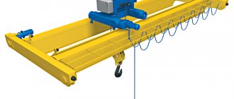
Garage crane is used for:
- removing the engine;
- lifting beams, bridges;
- movement of dimensional units.
The crane contains a hydraulic drive and operates through a system of communicating vessels. The method allows you to make the rise smooth.
Stationary
The stationary crane is installed in large car repair shops and is securely attached to a monolithic foundation. The mechanism has a boom with a rotating system and is equipped with a manual drive. Allows you to work on only one vehicle at a time.
It is important to calculate the installation location in advance, since it will not be possible to dismantle the structure without loss.
An integral advantage of a stationary crane is its large lifting capacity. It is provided by a monolithic support, which creates rigidity of the system.
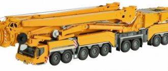
Portable
The hydraulic rolling crane has wheels on its base. The support is provided by the lower metal beams, which results in loss of load capacity readings. It is better to choose a faucet with a massive triangular support. By design they are divided:
- on cast solid supports with limited boom reach, but good load capacity;
- telescopic or folding - they have an increased boom reach, but reduce the load capacity by several times.
Important! Folding units need to strictly follow the instructions for lifting the permitted load. The arrow cannot withstand and, if the permitted standards are not observed, it breaks off.
Design and operating diagram of folding garage doors
The lifting (panel) gate system is a fairly simple mechanical device. The main and load-bearing elements are the frame, guides and a lever-spring mechanism that moves the sash. The mechanism can be controlled either manually or using an electric drive controlled by a remote control (remote control). When opening the gate, levers are used that are attached to the bottom of the sash, and two guides for the movement of rollers, fixed at the top at the ends of the sash. Opening is carried out by lifting the lower part of the door by the handle and is done quite easily, since the stretched springs of the lever mechanism help in opening the gate.
Scheme of operation of the lifting mechanism
There are two types of lifting gate mechanisms:
- Lever-spring is a fairly simple and reliable mechanism that is popular among garage owners. Installation features: precise adjustment of tension springs and high quality and precision installation of roller guides.
- With counterweights - used mainly on gates with a large leaf weight. The cable is attached to the lower corners of the sash and passes through the block to a counterweight mounted on the other edge of the winch.
Drawing of overhead garage doors
When preparing a drawing to suit your opening dimensions, you should use ready-made solutions, slightly adjusting them to your dimensions. Here is an example of drawings for making gates:
Drawing of lifting gates
Drawing of the frame, dimensions must be set to match your gate dimensions.
What is required for production
For the manufacture of the sash frame, rectangular profile pipes with dimensions of 40*20 and a wall thickness of 2 mm are most suitable. For transverse and longitudinal spars we also use profile pipes, but of smaller sizes - namely 20*20*2 mm, to reduce the weight of the structure. For sewing up the front and inner sides of the sash, a profile sheet is best suited, since it is already coated with an anti-corrosion compound from the factory. You can also use galvanized sheets.
For guides, it is ideal to use a channel up to 20 cm wide. The size of the channel shelf depends on the width of the rollers used in your particular case. The box to which the lever-spring mechanism is attached in the garage doorway can be made from a 100*50 mm wooden beam. For these purposes, you can also use a metal corner with a 50 mm shelf.
Support-sliding rollers and lever-spring rollers are purchased separately at a store specializing in sliding gates.
For thermal insulation of gates, for reasons of price and quality, it is advisable to use polystyrene foam with a thickness of 40 mm and a density of 15 to 25 kg/m 3.
Step-by-step manufacturing instructions
- The frame installed in the opening is the main strength element of the gate. It bears the main load of the entire garage door system. The box is made from a 100*50 mm wooden beam or a thick metal corner. The width of the corner shelf should be 1.5 times wider than the sash thickness, that is, if the sash thickness is 40 mm, then we take the corner with shelves of at least 60 mm. The box parts are installed in the letter P, two on the sides of the opening, one on top. If we use wood, we fasten it with 100 mm self-tapping screws into pre-prepared wooden embeds. In the case of using a corner, we fasten it using anchor bolts, however, they are perfect for the first case.
- Let's start assembling the frame for the gate leaf. We cut the profile pipe to size according to your drawing. We lay out the frame elements on a flat horizontal surface and, after checking the right angles, use a square to grab the joints. Before fully welding the joints, it is necessary to check the length of the frame diagonals with a piece of cord or tape measure. If necessary, you can adjust the product and begin fully welding the joints. We weld gussets at the corners of the frame, as shown in the drawing, to enhance the rigidity of the structure.
Welding joints of frame elements
We clean the weld seams from burrs and the entire frame from rust with a grinder.
- We coat the frame with an anti-corrosion primer and paint it with alkyd enamel in 2 layers with intermediate drying.
- We weld brackets with rollers to the upper corners at the end.
- We place it on the frame and fasten the profile sheet with self-tapping screws with a drill and a rubber washer in increments of 15–20 cm. We attach the sash opening handle to M8-M10 bolts. This operation can be done at the end of installation work, which significantly reduces the physical stress on workers when checking the operation of mechanisms.
- We attach guides for the rollers to the ceiling. We check their parallelism and perpendicularity to the opening.
- We temporarily install the sash in the opening to mark the place where the lever-spring mechanism is attached. We remove the sash and attach the levers along the marks to its ends with self-tapping screws.
Checking the correct operation of the gate
Gate leaf installation
How and with what to insulate
Classic insulation materials used for these purposes are mineral wool and polystyrene foam boards. Foam plastic compares favorably with mineral board in that it does not shrink over time. We will insulate the sash with polystyrene foam 40 mm thick and density 20. First, we insert the foam without fastening into the sash to cut all the necessary trims to size. Sheets of foam plastic are glued to the profile sheet from the inside between the side members using “liquid nails”. Next, we fasten the inner plane of the sash with a sheet of galvanized sheet using self-tapping screws and a drill.
Insulation of gate leaves with polystyrene foam
Exploitation
For ease of use of garage doors, you can install an electric drive with a control unit operating from commands coming from the remote control to the existing opening system. When purchasing a drive, make sure that it is suitable for your type of gate.
In winter, rubber seals must be periodically lubricated with silicone grease to avoid freezing of the leaf and damage to the seal when opening the gate. Also, periodically pay attention to lubricating the lever system and support rollers.
Video: homemade folding garage doors
Video: lift-and-swivel design
The overhead garage door system is easy to implement on your own, so almost any car owner with welding and metal working skills can do it, the main thing is to be more careful with the installation of such critical elements as guides. From the start of work to the complete installation of the gate, you can handle it in 2 days if you invite friends or acquaintances to help.
Homemade lifting devices are an indispensable tool for a garage where major car repairs are planned. With the help of such an auxiliary device, you can easily remove the car engine, lift the edge of the body, or even the entire car.
Easy-to-make homemade lifting mechanisms make work several times easier and faster not only in the garage, but also near the house. They are indispensable for construction and repair, moving construction waste, and unloading heavy loads.
It is necessary to raise the garage - the reason is deformation of the foundation
In garage cooperatives, which were formed back in Soviet times, they did not particularly care about the quality and reliability of the foundation. Nowadays, such “islands” of metal garages are often located next to new microdistricts.
And with large construction and deep pits for high-rise buildings, soil deformation is inevitable. Therefore, the problem often arises - how to raise a metal garage if the foundation has sagged or skewed.
Causes of foundation deformation
Reasons for deformation of the strip foundation or subsidence of the soil under the garage:
- uneven weight of metal garage walls. Often homemade welded structures are made from sheets of metal of different thicknesses;
- Along the walls of the garage there are always shelves with tools and other little things necessary for a garage owner. They also add stress to a weak foundation;
- if there is a large-scale construction project nearby, then soil deformation is inevitable, so the foundation “floats” and needs to be strengthened;
- seasonal rainwater or rising groundwater can also cause soil heaving and deformation of the foundation and ground under a metal garage;
- weak soil - clay, loam and sandy loam with sudden temperature changes also pushes out the old foundation strip during seasonal heaving if the foundation is located above the freezing point of the soil.
You must first find out why the garage is warped and only then begin lifting and repairing it.
Types of lifting mechanisms
Before you start assembling a garage faucet with your own hands, you should choose which mechanism will suit you best. Load lifting machines belong to a fairly important category of industrial and household equipment. They are designed to move various loads in a vertical or inclined direction. A useful feature for motorists is the ability to move a load suspended on a hook to the side, thereby freeing up space for work. When designing a car lift, it is advisable to supplement it with a similar option - this way you can expand the list of actions performed in the garage.
What characteristics should a garage lift have?
Since the device will be used in the rather cramped conditions of a standard garage, certain requirements are put forward for it. Firstly, it should not be too large - such a car lift, despite its high power, takes up a lot of space, which is very undesirable in such a small area. Secondly, it is recommended to give preference to mechanisms with a small vertical stroke, otherwise you risk running into the ceiling.
The second requirement is carrying capacity. It is calculated based on the types of work for which the car lift is being developed. The dimensions of the mechanism also depend on the purpose. If a regular jack is suitable for regular wheel replacement, then for larger-scale work you will need a car lift with a platform, although for such important actions it is recommended to resort to the help of professional equipment.
Materials and tools
When constructing a garage lift with your own hands, you need to have in your arsenal not only drawings of the future device, but also arm yourself with a set of tools and high-quality, load-resistant materials. First of all you will need:
As the planned homemade garage winch becomes a reality, the list of components for it may change slightly, depending on your specific requirements for the mechanism.
How to assemble a simple faucet
Before assembling the lift with your own hands, you should create a detailed drawing indicating the dimensions of all parts and the method of attaching them to each other. At this stage, the type of mechanism is determined - it could be a beam crane for a garage, a regular winch suspended from the ceiling, a powerful jack with manual, electric or hydraulic control. Often, craftsmen even construct such complex devices as a two-post lift that can withstand the weight of a passenger car.
One of the simplest models, which includes a homemade winch for a garage, consists of a cantilever fixed boom mounted on a vertical stand made of steel pipe. A trolley with a winch is mounted on the boom. The vertical pipe is welded to the base. This could be a massive steel plate or the garage foundation itself. A homemade garage winch will be more reliable if you secure the upper end of the rack to the ceiling of the room.
The working part of the mechanism is a small winch. If it is homemade, the faucet will lose some reliability, so it is better to purchase a factory-made device.
A steel cable is passed through a groove in the winch block, at the end of which a hook is installed. By rotating the winch handle, you will set the block with the cable in motion, lifting the load to a given height.
Lift operating rules
To make a lift yourself, you need to put in a lot of effort. But in order for this unit to work more efficiently, it is necessary to follow all the rules for its operation:
- Before using the lift, be sure to remove the bolts that hold the engine and vehicle frame together.
- A loop of steel cable is placed under the engine. A lift hook is placed on its end.
- Search the circuit.
- Over time, the movement will transfer to the drive shaft, which will transmit force to the cargo, which will lead to tension in the cables.
- The power unit is lifted slowly and carefully to avoid damage.
- After removing the engine using a lift, it is necessary to stop its operation. The load will now be held by the gearbox.
- The vehicle can be moved away and a sturdy table can be installed in its place to support the load from the engine.