Having an autonomous source is perhaps the most optimal and profitable way to solve the water supply problem. Moreover, it is extremely necessary if the process of hydrodrilling a well is used during construction. Using this technological process, well development will be quick and inexpensive, especially if you involve the MBU 125 drilling rig in the work.
Drilling rig MBU-125
The MBU 125 drilling rig is used when carrying out workover work, drilling exploration and production wells with downhole motors and a rotor, and in existing wells for kicking off the second table. This installation is capable of drilling a well to a depth of 2.7 kilometers.
A special feature of the MBU 125 mobile unit is that it can be used in temperate climates with a temperature range from -45° to +45°, in areas of those deposits where the hydrogen sulfide content is less than six percent.
The presented mobile drilling rig is produced in several cities of Russia, including Kostroma, Kungur and Petropavlovsk. The average price of a factory-installed installation that has passed factory tests and is fully ready for operation is about forty million rubles.
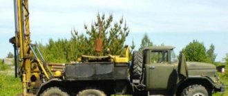
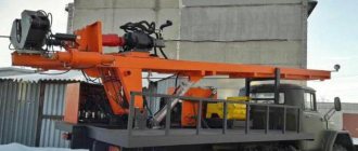
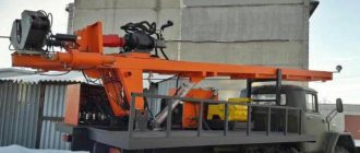
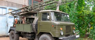
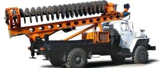
Photo of drilling rig MBU 125
Mobile Drilling Rig MBU 125 (Full set), Moscow
Mobile Drilling Rig MBU 125 (modernized) - a modified MBU-125 complex for carrying out work in tropical conditions
The MBU125 mobile unit is designed for drilling production and exploration wells with a rotor and downhole motors.
The conditional depth of drilling wells is 2700 m (when drilling with a column of 28 kg/m).
The installation consists of the following main blocks: – a lifting unit on a BAZ-69096 all-wheel drive chassis with increased load capacity – a mobile unit of a drilling base and receiving walkways on a three-axle trailer OZTP-84703
MBU-125 rigs are quite well-known all over the world, well-proven in operation in any conditions, mobile drilling complexes. The simplicity of their installation and operation puts them at the forefront in the segment of mobile drilling equipment, first of all, not forgetting the most important price-quality ratio.
For a long time, the main problem of the MBU-125 complexes was the need to modify the drilling complex on site, in light of problems that arose and the inconsistency of some components with drilling conditions. Our company managed to solve this problem. At the moment, we are ready to provide a complex that has been clearly tested over the years, modernized taking into account all the errors and inaccuracies in the standard installation.
Thanks to a number of engineering solutions, our company has managed to significantly increase the reliability of drilling equipment, which has a striking impact on the subsequent cost of service.
And finally, the most important thing: Our company offers not only installation, but a full range of services, starting with the manufacture of the installation and its infrastructure, ending with all issues related to its subsequent operation.
Equipment of the improved MBU-125 The equipment is complete and does not require any additional elements, structures or units to start drilling.
The package includes 14 unique items, each of which is modified taking into account the experience of drilling MBU-125 in various climatic conditions and in different operating conditions.
1. Mobile drilling rig MBU-125 in its standard factory version on the BAZ-69099 chassis 2. Pump-power unit with UNB-600 pump 3. Power drive with SA-25 diesel engine 4. Circulation system 120 m3 5. Blowout prevention equipment OP 5 -230/80-35 6. Diesel power plant 100 kW 7. Drilling key AKB-3M2 8. Spider 125 tons 9. Compressor 4VU 10. Receiver 2.7 m3 11. Drilling rope drum for bypass 12. Universal key 13. Capacity for fuels and lubricants 25 m3 PTMU in the amount of 2 pieces 14. Welding transformer 400 A 24x30
At the moment there are 2 units available in this configuration!!!
Device
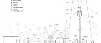
The MBU 125 installation is a tractor consisting of the following blocks:
- Lifting unit located on an all-wheel drive chassis with increased load capacity BAZ – 69099;
- A mobile unit of receiving walkways and drilling base placed on a three-axle trailer.
In addition, the installation is equipped with the following safety devices:
- Hook block stroke limiter;
- Hook load limiter;
- Sound signal when the mast is extended;
- Limitation of air pressure of a pneumatic installation;
- Hydraulic oil pressure limitation;
- Air and oil filters;
- Temperature indicator light;
- Emergency and warning lamps for engine operation located on the driller's console.
MBU 125 in working position
Mechanization devices and mechanisms:
- Auxiliary hydraulic winch;
- Leveling the horizontal position;
- Four hydraulic jacks;
The MBU 125 drilling rig provides automatic removal of moisture from the pneumatic system.
To work in the dark, the following equipment is used:
- Installation lighting;
- Lighting of the working platform and winch;
- Illumination of the horseback worker's balcony;
- Signaling red lamps located on the frame of the crown block;
- Lighting of the hook block and mast route.
Components for the MBU 125 drilling rig:
| Device | Characteristics |
| Drilling rotor RUP 560: | |
| Mechanical: | |
| - through hole | 1226 mm |
| - drive unit | 560 |
| - maximum torque | 20 kn*m /2000 kgf*m |
| — permissible load on the wedge grip and table | 180 kN/ 240 tf |
| — maximum rotation speed | 150 rpm |
| Hydraulic: | |
| - through hole | 1226 mm |
| - drive unit | 560 |
| - maximum torque | 160 kN*m /1600 kgf*m |
| — permissible load on the wedge grip and table | 120 kN/ 160 tf |
| — maximum rotation speed | 360 rpm |
| Drill swivel brand VB 100: | |
| — maximum rotation speed | 360 rpm |
| — bore diameter | 1226 mm |
| — diameter of logging cable | 8…11 mm |
| Block of walkways and drilling base: | |
| - permissible load | 1226 kN/ 125 tf |
| — distance between the ground and the rotor beams | 4500 mm |
| — maximum load on candlesticks | 80 tf |
| Number of axes | 6 |
| Maximum load | 10 tf |
| Chassis engine: | |
| - quantity | 1 |
| - type | YaMZ-8424 |
| - power | 330 (450) |
| - transmission | mechanical |
| Hydraulic release: | |
| — developed force | 49 kN/5 tf |
| — stroke of the rod | 950 mm |
| Hook block: | |
| — number of rollers | 4 |
| — maximum workload | 125 tf |
Mobile drilling rig MBU-125 on BAZ-69099 chassis
The MBU-125 installation is designed for drilling production and exploration wells with a rotor and downhole motors.The conditional depth of drilling wells is 2700 meters (when drilling with a column of 28 kg/m).
The installation consists of the following main blocks:
— a lifting unit on a BAZ-69099 all-wheel drive chassis with increased load capacity;
— mobile unit of the drilling base and receiving walkways on a three-axle trailer OZTP84701A;
SPECIFICATIONS
LIFTING BLOCK
Permissible hook load, Kt(tf)
| 1226(125) | |
| Drive mechanisms | Chassis drive motor YaMZ-8424 |
| Drive power, kW(hp) | 330(450) |
| Tower: | |
| — distance from the ground to the axis of the crown block, mm | 37000 |
| — length of the lifted candle, mm | 24000 |
| Capacity of the magazine of the riding platform, m | |
| — drill pipes with a diameter of 114 and 127 mm | 2700 |
| — drill pipes with a diameter of 73 and 89 mm | 3000 |
| Travel system: | |
| - equipment | 4 x 5 |
| — diameter of the traveling rope, mm | 28 |
| Drilling winch: | |
| — traction force, kN(tf) | 191(19,5) |
| — lifting speed of the traveling block, m/s | 0,15…1,5 |
| Hydrodynamic brake: | |
| - inclusion | Operative, disc pneumatic clutch |
| — lowering speed of the hook block with a load weighing 75 tons, m/s | 0,9 |
| Auxiliary hydraulic winch: | |
| — permissible load, kN(tf) | 29,5(3) |
| Manifold (riser with drilling sleeve): | |
| — flow area, mm | 76 |
| — working pressure, MPa (kgf/cm2) | 19,6(200) |
| Emergency electric drive: | |
| — electric motor power, kW | 30 |
| — hook block lifting speed at permissible load, m/min | 0,8 |
| — maximum lifting speed of the hook block, m/min | 2,9 |
| Lighting, V | 220, (emergency 24) explosion-proof |
| Overall dimensions of the lifting block (transport), mm | 28000 x 3100 x 4500 |
| Weight of the lifting unit in transport position, kg | 60000 |
ACCESSORIES
| Drilling rotor RUP560: | ||
| - drive unit | Mechanical | Hydraulic |
| — through hole, mm | 560 | 560 |
| — permissible load on the table and wedge grip. kN(tf) | 1226(125) | 1226(125) |
| — drive power, kW(hp) | 180(240) | 120(160) |
| — maximum torque, kN-m (kgf-m) | 20(2000) | 16(1600) |
| — highest rotation speed, s-1 (rpm) | 2,5(150) | 1,66(100) |
| Drilling swivel VB125: | ||
| — permissible load, kN(tf) | 1226(125) | |
| — bore diameter, mm | 75 | |
| — highest rotation speed, s-1 (rpm) | 6(360) | |
| — diameter of the short-circuit cable, mm | 8…11 | |
| Drilling base and walkway block: | ||
| — distance from the ground to the rotor beams, mm | 6000 | |
| — permissible load, kN(tf) | 1226(125) | |
| The order stipulates: A) Method of rotor drive R-560 (mechanical or hydraulic) B) Standard sizes of rotor wedges R-560 - 60, 73, 89,102, 114, 127, 140, 146, 168, 178, 194, 219, 245, 273, 299, 324, 340 (for an additional fee) | ||
Specifications
Technical characteristics of the MBU 125 drilling rig:
| Characteristics | Indicators |
| Lifting block | 1126 kN/125ts |
| Tower: | |
| - length of the raised candle | 24000 mm |
| — distance between the ground and the axis of the crown block | 37,000 mm |
| — maximum workload | 125 tf |
| — device type | retractable |
| — maximum statistical test load | 156 tf |
| Capacity of stores of horse worker's beds | |
| — Tubing, as well as drill pipes with a diameter of 89 and 73 mm | 3000 |
| — drill pipes with a diameter of 127 and 114 mm | 2700 |
| Travel system: | |
| — diameter of the traveling rope | 28 mm |
| - equipment | 4x6 |
| Drilling winch | |
| — traveling block: lifting speed | 0.15… 1.5 m/sec |
| — tractive force of the drill drum | 191 kN/19.5 tf |
| Hydrodynamic brake: | |
| — hook block with load: descent speed | 0.9 m/sec |
| - inclusion | operational, performed using a pneumatic disc clutch |
| Auxiliary hydraulic winch: | |
| - permissible load | 29.5 kN/3 tf |
| Manifold: | |
| — developed pressure | 19.6 MPa/200 atm |
| — flow area | 76 mm |
| Emergency electric drive | |
| — hook block lift: max. speed | 2.9 m/min |
| - engine power | 30 kW |
| — lifting the hook block from max. load: speed | 0.8 m/min |
| Lighting | 220, explosion-proof |
| Weight in transport position | 60,000 kg |
| Transport dimensions | 28000х3100х4500 mm |
Video review of the mobile drilling rig MBU 125:
Mobile drilling rig MBU125
- Purpose
The mobile drilling rig MBU125 is designed for drilling production and exploration wells with a rotor and hydraulic downhole motors, drilling sidetracks, repair and restoration of oil and gas wells in macroclimatic areas with moderate and cold climates at ambient temperatures from minus 45°C to plus 45°C . Placement category 1 according to GOST 15150.
MBU125 allows you to perform the following operations (with the appropriate configuration): - drilling wells with a rotor or hydraulic downhole motors; - drilling lateral wellbores; - tripping operations with drilling and tubing pipes, sucker rods; - mechanized make-up of drill and tubing strings ;- drilling out sand plugs and cement bridges with a rotor or hydraulic downhole motors; - setting up cement bridges in wells through the tower manifold; - flushing wells through the tower manifold; - various emergency response works; - development of wells after completion of drilling operations; - installation and dismantling installation and other equipment at the well; - movement on roads of all categories.
2. Delivery set (basic):
- lifting block on an all-wheel drive chassis - drilling base - receiving bridge - ramp - drilling rotor complete with a wedge grip - drilling swivel - driving pipe VBT - drilling sleeve - sling - drilling parameters control devices (for 3 parameters) - spare parts - accompanying documentation and operational - tackle rope
The installation can be equipped with additional equipment as agreed with the Customer: top power drive, pumping units, drilling fluid preparation and storage units, energy unit, top-up tank, drilling parameters monitoring devices with an expanded number of controlled parameters and other equipment.
3. The design of MBU125 provides:
1. load limiter on the hook;2. hook block lifting height limiter;3. blocking the drive when the guards are removed;4. blocking the inclusion of the rotor drive when the wedge grip wedges are raised;5. device for belaying a worker on horseback with a counterweight;6. emergency evacuation device for the riding worker;7. signaling between the driller and the riding worker;8. foldable tunnel-type fencing (on the lower section of the tower)9. the emergency drive of all mechanisms and systems MBU125 is capable of maintaining the operation of the installation with loads on the hook of up to 125 tons;10. 12V lighting system (main and emergency);11. auxiliary hydraulic winch - 2 pcs.;12. backup control panel for auxiliary winch13. modernized rotor RUP-560M, in relation to RUP-560, with increased safety factors of individual elements by 25...30%;14. device for transporting a drum with a 1000m traveling rope.
4.Specifications
| Permissible load on hook, kN (tf) | 1226 (125) | |||||
| Maximum test load on hook, kN (tf) | 1533 (156) | |||||
| Conditional drilling depth (drill string weight 28 kg/m), m | 2700 | |||||
| Conditional depth during repair and development (tubing string mass 14 kg/m), m | 5400 | |||||
| Mounting base – self-propelled all-terrain chassis*: | ||||||
| — Developer and manufacturer: Kungur Machinery Plant, Minsk Wheel Tractor Plant, Bryansk Automobile Plant | PS6MZKT-7003BAZ-69099 | |||||
| — Wheel formula | 12x12 | |||||
| — Brand and drive power of the self-propelled chassis, kW (hp): TMZ-8431.10 or Caterpillar C15 with Allison 4700 OFS GMT | 346 (470) 354 (480) | |||||
| Tower: | ||||||
| — telescopic, two-section, inclined with an open front edge, assembled with a crown block, with the possibility of installing a top drive system | ||||||
| — distance from the ground to the axis of the crown block, m | 37 | |||||
| — lifting the tower using one or two hydraulic cylinders | ||||||
| — extension of the upper section using a hydraulic cylinder | ||||||
| — control of lifting the tower and extending the upper section | remote control | |||||
| Horse worker's balcony: | ||||||
| — automatically unfolds when the upper section of the tower is extended | ||||||
| — magazine capacity of the riding worker’s balcony, m: — for drill pipes ø 114 mm — for tubing and drill pipes ø 73 and 89 mm | 27005400 | |||||
| — drill stand length, m, no more | 21 | |||||
| Travel system: | ||||||
| — tackle system equipment | 4x5 | |||||
| — diameter of the traveling rope, no more, mm | 28 | |||||
| — with a hoisting rope bypass device | ||||||
| Winch: | ||||||
| — single-drum, two-speed, with disc pneumatic clutches, two-pulley band brake | ||||||
| — traction force, kN (tf) | 191 (19,5) | |||||
| — hook block lifting speed, m/s | 0,15…1,5 | |||||
| Hydrodynamic brake: | ||||||
| — operational activation, with a pneumatic disc clutch; lowering speed of the hook block with a load weighing 84 tons, m/s | 0,9 | |||||
| Working/installation hydraulic system: | ||||||
| - pump model | 310.4.112 – 2 pcs./NSh-50M4 – 1 pc. | |||||
| — nominal pressure, MPa (kg/cm2) | 19,6 (200)/17,6 (180) | |||||
| — nominal flow, l/min | 380/113,7 | |||||
| Hydraulic release 2 pcs.: | ||||||
| — rod stroke, mm | 950 | |||||
| — developed force, kN (tf) | 49 (5,0) | |||||
| Auxiliary hydraulic winch, 2 pcs.: | ||||||
| Permissible load on hook, kN (tf) | 29,5 (3,0) | |||||
| Manifold (riser with drilling sleeve): | ||||||
| — flow area, mm | 75 | |||||
| — working pressure, MPa (kgf/cm2) | 24,5 (250) | |||||
| Emergency electro-hydraulic drive: | ||||||
| — electric motor power, kW | 30 | |||||
| — permissible load on the hook (quiet running), kN (tf) | 1226 (125) | |||||
| — speed of lifting the hook block at low speed, m/min, no more | 0,7 | |||||
| — speed of lifting the hook block at high speed, m/min, no more | 2,9 | |||||
| Main and emergency lighting, V | 12 | |||||
| Drilling base: | ||||||
| - foldable (parallelogram) | ||||||
| — clearance from ground level to rotor beams, m* | 4,7/6,0 | |||||
| — permissible load, kN (tf) | 1226 (125) | |||||
| Drilling swivel VB-125: | ||||||
| — permissible load, kN (tf) | 1226 (125) | |||||
| — bore diameter, mm | 75 | |||||
| — highest rotation speed, s-1 (rpm) | 6 (360) | |||||
| Drilling rotor complete with pneumatic wedge grip: | ||||||
| — type, drive* | RUP-560M, mechanical | RUP-560, hydraulic | ||||
| — through hole, mm | 560 | 560 | ||||
| — permissible load on the table and wedge grip, kN (tf) | 1226 (125) | 1226 (125) | ||||
| — drive power, kW (hp) | 150 (200) | 120 (160) | ||||
| — torque, kN*m (kg*m) | 19,5 (2000) | 15,7 (1600) | ||||
| — highest rotation speed, s-1 (rpm) | 2,5 (150) | 1,66 (100) | ||||
| — ø pipes held by wedge suspension, mm* | 60-340 | |||||
| Drill pipe VBT: | ||||||
| — size of the square part, mm* | 89x89, 112x112, 133x133, 140x140, 80x80 | |||||
| — length, mm | 11300 | |||||
| Reception bridge with racks *: | Transportable or wheeled | |||||
| Ramp, height, mm | 300 | |||||
| Weight of the lifting unit in transport position, no more than, kg | 65000 | |||||
| Service life, years | 9 | |||||
* - according to the Customer’s technical specifications
The mobile drilling rig MBU125 complies with the Federal norms and regulations in the field of industrial safety “Safety Rules in the Oil and Gas Industry” dated March 12, 2013 (as amended by Rostechnadzor Order No. 1 dated January 12, 2015).

