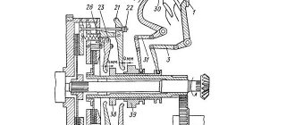
The clutch of the YaMZ-238 model is double-disc, dry, friction type, with a peripheral arrangement of cylindrical springs
The clutch housing 16 (Fig. 1), stamped from sheet steel, with the pressure disk 19 assembly is installed on the engine flywheel 20, and the driven disks 21 are installed on the splined part of the gearbox input shaft.
The front and rear driven discs are installed in a specific position, as shown in the figure.
The driven clutch discs are clamped by a constant force of cylindrical pressure springs 17 between the engine flywheel, the middle and pressure discs.
Thermal insulating gaskets 18 are placed under the springs on the pressure plate side. The pressure and middle drive disks are connected to the flywheel by four tires located on the outer surface of the disks.
When clamped, the driven disks transmit engine torque to the transmission input shaft.
The clutch is released using clutch 11.
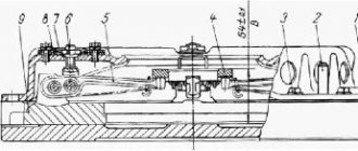
The clutch with the bearing, moving towards the engine, moves the pressure disk away from the driven disk, transmitting force through four rigid pull-out levers 5. The working stroke of the clutch release clutch, taking into account free play, must be at least 18.2 mm (size “D”) .
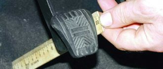
The amount of free play is regulated by the clutch release mechanism. The thrust ring of the pull-out levers moves towards the gearbox by 27 mm due to the permissible wear of the friction linings.
Guaranteed clearances between the driven disks and the friction surfaces of the flywheel, middle drive and pressure disks when the clutch is disengaged as the linings wear are ensured by a mechanism for automatically adjusting the withdrawal of the middle disk, which consists of rods 1 fixed in each of the four spikes of the middle drive disk, split rings 2, to move along the rod which requires a certain force, thrust bars 4, which are bolted to the flywheel with the clutch casing, and disc springs 3 installed on the rod between ring 2 and bar 4.
When the clutch is released, the pressure plate 19 moves back at least 2 mm and releases the rear driven disk 21.
The middle drive disk 22, under the action of the spring 23, also moves back, until the ring 2 stops in the bar 4 through a disc spring, by an amount of 1.2+0.1 mm, freeing the front driven disk.
As the clutch friction linings wear out, the middle drive disk, under the action of the pressure springs of the pressure disk, moves to the flywheel, the rings 2 rest against the clutch housing, moving along the rods 1 and maintaining the size between the rings and the disc springs.
When the driven disc linings wear out, the end of the clutch release clutch will rest against the end of the gearbox input shaft bearing cover; in this case, replace the worn linings of the driven discs with new ones.
Installing the clutch on the engine
Installing the clutch on the engine is carried out in the following order:
1. install the front driven disk;
2. install the middle drive disk with rods;
Z. install the rear driven disk;
The following clutch discs can be installed: front 238-1601130-B, rear 238-160113 1 (not interchangeable); or two disks 238-1601 130-G2 (interchangeable).
Two disks 238-1601130-G2 can be installed instead of the front disks 238-1601130-B and rear 238-160113 1. And vice versa.
The end of the extended part of the disk hub 238-1601130-G2 is marked 238-1601130-G2.
When installing them, the following conditions must be met:
— disk to the flywheel — the marked side of the hub to the engine;
— disk to pressure plate — marked side of the hub to the gearbox.
4. install the pressure plate with housing assembly, securing it to the flywheel using eight short bolts;
5. put split rings 2 on rods 1 until they stop at the clutch housing;
6. put on four. Belleville springs with the convex side to the split rings:
7. Install four thrust bars and secure them with the casing to the flywheel using eight long bolts.
After installing the clutch on the flywheel, make sure that the rings on the rods rest against the housing, providing a gap of 1.2+0.1 mm between the rings and the disc springs when the clutch is engaged.
Adjust the clutch free play.
Attention! Lack of free play of the clutch will lead to failure of the pressure bearing and slipping of the discs.
After adjustments, check the clutch for lack of “driving”. Carry out this check with the engine running with first gear engaged and the clutch disengaged.
Clutch T-150/T-150K: diagram, principle of operation, adjustment
The clutch on the T-150 and T-150K tractors is responsible for smooth starting. The serviceability of the module and its correct adjustment play an important role in this. How the clutch on the wheeled and tracked T-150 works, what parts it consists of, how to replace spare parts and make adjustments - we will answer these and other questions in this article.
The role of clutch on T-150 and T-150K
The clutch is one of the key elements of the transmission. It takes on most of the energy when selecting speeds and protects the tractor from overloads by damping vibrations.
The operating principle of this module on the T-150 and T-150K tractors is no different from the mechanics of its functioning on passenger cars. It disconnects the motor from the transmission and also connects them when it is necessary to change gears. The need to install a clutch is due to the fact that the engine runs continuously, but the wheels do not. If the T-150 didn't have a clutch, you'd have to turn off the engine every time the tractor stopped. When starting, this unit again combines the rotating engine and the static box, carefully connecting the shafts to each other. Due to this, the tractor moves off smoothly.
Clutches T-150 and T-150K: what they have in common and how they differ
The clutch design on the tracked T-150 and the wheeled T-150K is as similar as possible, but there are still differences - in the details of the drive mechanism. The clutch housing of a crawler tractor is indirectly connected to the transmission housing. For the wheeled modification, a spacer housing is mounted between them. Because of this difference in installation, the T-150K clutch shaft is longer than the T-150.
Another difference in the design of the clutches of wheeled and tracked tractors lies in the servo mechanism, which is installed to reduce the energy expended to disengage the clutch. Depending on the modification, the amplifier is mounted:
- on pneumatics (on the wheeled version);
- on mechanics (on the version with tracks).
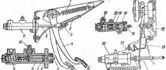
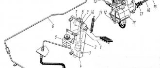
Diagram of the mechanical servomechanism of the T-150 clutch
The clutch release drive is shown schematically in this figure. The numbers indicate the following details:
- pedal;
- double arm lever;
- earring;
- craving;
- spring element;
- conn. craving;
- support part;
- release housing bearing;
- nut for adjustment;
- stopper;
- spring stop bolt;
- fork;
- ring of levers for spinning;
- thrust element;
- lever arm.
The spring of the mechanical servomechanism, when the clutch of the T-150 tractor is engaged, moves the pedal as far back as possible. The foot pedal is held by pressing the amplifier earring on the smaller protrusion of the two-arm lever. When the pedal is pressed, the spring stretches. After this, the spring is compressed, which leads to rotation of the two-arm lever. The consequence of this is that the clutch of the tracked T-150 is disconnected.
Diagram of the pneumatic servomechanism of the T-150K clutch
The following digital symbols are marked on the wheel tractor clutch release drive diagram:
- pedal;
- lever arm;
- linkage;
- tracking device;
- drain hose;
- release bearing;
- nut for adjustment;
- spring stop;
- spring stop bolt;
- fork;
- release stop bearing;
- ring of release levers;
- lever arm;
- supply hose
The housing of the tracking device of the pneumatic servomechanism of the clutch of the T-150K tractor is connected to the rod. There is a pneumatic chamber located on the coupling body, which is connected to a tracking device using pipelines.
Clutch basket for T-150/T-150K tractors
When the pedal is depressed, the plunger moves along its axis, opening the valve. Through the resulting hole, air under pressure enters the air-compression chamber. This leads to movement of the chamber rod, which in turn stops the T-150K clutch. If you release the pedal, the plunger stops pressing on the valve, and it closes the hole, moving to its original position.
Features of the clutch design on different modifications of the T-150/T-150K
Over the years of production of tracked and wheeled tractors, many different modifications have been produced. And for different variations of special equipment, excellent clutch options were offered.
Most T-150 series tractors were equipped with dry-type friction double-disc clutches that were permanently closed. But you can also find a single-plate clutch. Initially, the discs were made from alloys with a high asbestos content, but in recent years the composition of the material has changed.
Types of clutches and parts with catalog numbers for T-150/T-150K with SMD-60, YaMZ-236, YaMZ-238, Deutz, MAZ engines
To make it easier to navigate the variety of parts and their purposes, we offer the following table.
| Part number | Part name | Which engine are they suitable for? | Peculiarities |
| 151.21.021-3 | Clutch body | installed with SMD-60 motor | |
| 150.21.022-2A | Basket | ||
| 150.21.222 | Squeeze glass bearing | ||
| 01M-2126 | Including plug | suitable for Deutz engine | |
| 01M-21C9 | Clutch off | ||
| 151.21.034-3 | Clutch shaft | suitable not only for SMD engine, but also for YaMZ | |
| 150.21.0243A | Driven disk with linings | ||
| 172.21.021 | Clutch housing | spare parts are supplied with the YaMZ-236 engine, double-disc clutch | it also fits the Deutz engine |
| 236T-150-1601090 | Basket | for two disks | |
| 150.21.222 | Squeeze glass bearing | the same as for the T-150 clutch with SMD-60 | |
| 01M-21 S9 | Clutch off | ||
| 151.21.034-3 | coupling shaft | ||
| 150.21.024-3A | Driven disk (thickness 17) with linings | ||
| 172.21041 | Clutch body | YaMZ-236, single-disc petal clutch | |
| 181.1601090 | Petal clutch basket | for one disk | |
| 171.21.222 | Release bearing cup | ||
| 172.21121 | Power plug | ||
| 172.21.032/034 | Clutch in clutch release assembly/shaft | ||
| 172.21.024 | Driven disk with linings (thickness 24) |
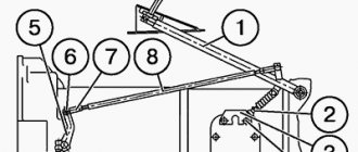
Adjusting the position of the thrust ring of the pull-out levers
When assembling the pressure plate and housing assembly, adjust the position of the thrust ring.
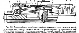
This adjustment is made in a device having an installation size of 27 ± 0.1 mm (Fig. 2) with adjusting nuts 6 pull-out levers with the casing and pressure disk in a fixed position.
By adjusting, ensure dimension “B” is equal to 64 ± 0.1 mm, while the thrust surfaces of all four release levers 5 must simultaneously touch the thrust ring 4. A misalignment of the thrust ring will lead to uneven release of the pressure plate when the clutch is disengaged or its abnormal operation.
After adjusting the position of the thrust ring using the adjusting nuts 6, install the locking 7 and support plates 8 of the adjusting nuts. Tighten all eight bolts securing the locking and support plates, installing spring washers under the bolt heads.
In the case of using a pressure plate with a casing complete with driven disks after repair, on which friction linings with a thickness of 4.15 mm are installed, when adjusting the position of the thrust ring, set dimension “B” to 67+0.1 mm.
Composition of the unit
Clutch
The double-disc clutch on a MAZ car is a complex mechanism that consists of the following components:
- Main flywheel with crater equipment;
- Release spring;
- Spring pressure;
- Split ring;
- Special rod;
- Stop bar;
- Lever pull mechanism equipped with a fork;
- A thrust ring connected to a pull-out lever;
- Adjusting nut;
- Support plate;
- Clutch release fork mounted with a roller;
- Clutch release device equipped with a bearing. It is attached to the bushing via a flange mounted to the gearbox housing;
- Special casing;
- Simple lever;
- Thermal insulation washer;
- Pressure disc;
- Middle drive type disc;
- Pressure type disc;
- Drive medium type drive;
- Discs: rear and front driven type.
From the last paragraph of this listing, the name of this type of clutch for Masks becomes clear.
Clutch Maintenance
Maintenance of the clutch is carried out similarly to the maintenance of the YaMZ-182 clutch (see above) with the addition:
Check each TO-1 and, if necessary, adjust the free play of the clutch release clutch.
The free play of the clutch release clutch, determined by the gap between the thrust ring and the clutch bearing (dimension “A” in Fig. 1. 3.2-4.0 mm), is achieved by adjusting the clutch release mechanism in accordance with the instructions in the vehicle operating instructions.
After adjustments, check the clutch for lack of “driving”. Carry out this check with the engine running with first gear engaged and the clutch disengaged.
Adjusting the free play of the clutch release clutch using the adjusting nuts of the release levers is strictly prohibited.
How to adjust the double-disc clutch of a MAZ car
Structure and functions of the clutch Malfunctions, causes and actionsAdjusting the clutch and drive
The MAZ double-disc clutch is a transmission element. When it functions correctly, the machine behaves calmly. However, in the event of a breakdown or other malfunction, malfunctions occur in the MAZ. In order for the truck to function properly, the clutch must be adjusted regularly. How to do this will be discussed further.
Torsional vibration damping and power take-off mechanism
Power units can be equipped with a mechanism for damping torsional vibrations and power take-off (Fig. 3), designed to dampen resonant torsional vibrations and protect transmission systems from destruction.
The mechanism is installed on the engine flywheel and consists of a pressure flange 1, a driven disk 2 with friction linings and a mechanism for damping torsional vibrations, packages of disc springs 5 and stepped bolts 6.
Driven disk 2 is constantly pressed to flywheel 3 through flange 1 by packages of disc springs 5 assembled on stepped bolts 6.
The step bolts are screwed into the flywheel until they stop. When installing stepped bolts, sealant UG-6 TU 6-01-1285-84 is applied to their threaded part, tightening is carried out with a force of 49-59 Nm (5-6 kgcm).
The number of packages of disc springs and bolts is selected so that the friction moment they create allows the transmission of torque from the flywheel to the power take-off shaft up to 1700 Nm (170 kgcm).
When the driven disk is loaded with a torque of more than 1700 Nm (170 kgcm), the force of the springs is not enough to hold the driven disk and it rotates relative to the flywheel and thereby protects further kinematic connection from destruction.
During operation, the mechanism does not require maintenance.
Possible malfunctions of the driven disk during operation are similar to malfunctions of the clutch driven disk.
Premature slipping of the driven disk can be eliminated by installing additional packages of disc springs together with the bolt and further checking the friction torque in the following order:
1. Lock the engine flywheel.
2. Load the driven disk of the mechanism with a torque of less than
1700 Nm (170 kgcm). the disc should not rotate relative to the flywheel.
3. Load the driven disk of the mechanism with a torque of 1700... 1900 Nm (170... 190 kgf). The disk must rotate relative to the flywheel.