Overview of the MAZ 5440 electrical circuit design
A separate part is allocated to indicate light signaling and lighting equipment: flashlights, spotlights, headlights, fog lights, lighting in the cabin.
Power supply is required for instruments located on the driver's panel, as well as an audible alarm that informs about problems with pressure in the brake system.
A significant part of MAZ electrical equipment is the mounting block, which contains fuses.
The device includes a multilayer printed circuit board, and if there is a short circuit in the MAZ electrical wiring and current-conducting harnesses, the unit fails. Sometimes the unit can be repaired, but more often it needs to be replaced.
When removing and installing the unit, it is important to carefully monitor compliance with the connection rules.
Current-consuming devices should be connected in accordance with the Euro MAZ electrical diagram.
Do not forget that electrical diagram drawings do not reflect the actual location of elements.
The graphic representation shows the connection of the components with each other.
The nodes can be connected in series or in parallel, the components are located in the circuit in a certain order established by the manufacturer.
However, before repairing the system, we advise you to carefully study the MAZ diagram, because if the elements are connected incorrectly, a significant breakdown of the system may occur.
Spare parts for electrical wiring MAZ 5440
On the website of the official dealer of the Minsk Automobile Plant you can select components for the electrical equipment of the MAZ 5440.
If you don’t know how to choose components, call the store manager. We will select the necessary spare parts, place an order and help organize delivery to any city in Russia.
Source
TRUCKS GAZ, ZIL, KAMAZ, URAL, MAZ, KRAZ
_________________________________________________________________________________________
Rear axle design MAZ-5551, 5335
Design and details of the rear axle Maz-5551, 5549, Maz-5335, 5336, 5337 The rear axle Maz-5551, 5549, Maz-5335, 5336, 5337 (Fig. 46) transmits torque from the engine crankshaft through the clutch and gearbox and the driveshaft to the drive wheels of the car and with the help of a differential allows the drive wheels to rotate at different angular speeds.
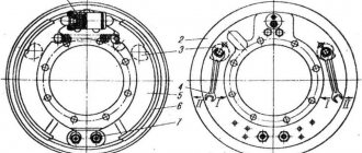
Rice. 46. Rear axle Maz-5551, 5549, Maz-5335, 5336, 5337 1 - wheel drive; 2 — rear wheel hub; 3 — rear wheel brakes; 4 - axle housing locking pin; 5 — guide ring of the axle shaft; 6 — axle housing; 7 — axle shaft; 8 - central gearbox; 9 — twin axle shaft seal; 10 — adjustment lever; 11 — brake expansion knuckle. The adopted structural and kinematic schemes for transmitting torque make it possible to divide it in the central gearbox, directing it to the wheel gears, and thereby unload the differential and axle shafts from the increased torque, which is transmitted with a two-stage final drive scheme of the rear axle Maz-5551, 5549, Maz-5335, 5336, 5337. The use of wheel gears allows, in addition, by changing only the number of teeth of the cylindrical gears of the wheel reducer and maintaining the center-to-center distance of the wheel gears, to obtain different gear ratios, which makes the rear axle suitable for use on different modifications of cars.
Rear axle gearbox Maz-5551, 5549, Maz-5335, 5336, 5337
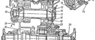
The rear axle gearbox Maz-5551, 5549, Maz-5335, 5336, 5337 (Fig. 47) is single-stage, consists of a pair of bevel gears with spiral teeth and a cross-axle differential. The gearbox parts are mounted in the crankcase 21, made of ductile cast iron. The position of the crankcase relative to the beam is determined by the centering collar on the mounting flange of the gearbox housing and, in addition, by the alignment pins. The drive bevel gear 20, made as one piece with the shaft, is not mounted on a cantilever, but has, in addition to two front tapered roller bearings 8, an additional rear support, which is a cylindrical roller bearing 7. Design of the Maz-5551, 5549, Maz-5335 gearbox , 5336, 5337 with three bearings is more compact, while the maximum radial load on the bearings is significantly reduced compared to a cantilever mount, the load capacity of the bearings and the stability of the bevel gear mesh adjustment are increased, which significantly increases their durability. In this case, the possibility of bringing the tapered roller bearings closer to the ring gear of the drive bevel gear reduces the length of its shank and thereby makes it possible to increase the distance between the gearbox flange and the gearbox flange, which is very important for a small vehicle base for a better location of the driveshaft. The outer rings of the tapered roller bearings are located in the crankcase 9 and are pressed all the way into the collar made in the crankcase. The bearing housing flange is attached with studs to the rear axle gear housing. These bearings support both radial and axial loads that occur in the mesh of a pair of bevel gears when transmitting torque. Rice. 47. Rear axle gearbox Maz-5551, 5549, Maz-5335, 5336, 5337 1 — bearing cover; 2 — bearing nut stopper; 3 — left bearing nut; 4 — axle gear; 5 — differential satellite; 6 — differential crosspiece; 7 — cylindrical bearing of the drive gear; 8 — tapered bearing of the drive gear; 9 — drive gear bearing housing; 10 - spacer ring; 11 — adjusting washer; 12 — oil deflector; 13 — oil seal cover; 14 - flange; 15 — flange nut; 16 — washer; 17 — oil seal; 18 — adjusting shims; 19 — gasket; 20 - drive gear; 21 — gear housing; 22 — driven gear; 23 - cracker; 24 - lock nut; 25 — driven gear limiter; 26 — right differential cup; 27 — dismantling bolt of the gearbox housing; 28 — thrust ring of the bushing; 29 — right bearing nut; 30 - tapered bearing; 31 — left differential cup; 32 — steel washer; 33 - bronze washer. The inner bearing has a tight fit on the shaft, and the outer one has a sliding fit, which allows you to adjust the tension in these bearings. A spacer ring 10 and an adjusting washer 11 are installed between the inner rings of the tapered roller bearings. By selecting the thickness of the adjusting washer, the required preload in the tapered roller bearings is determined. The cylindrical roller bearing 7 of the drive bevel gear is installed in the bore of the housing of the rear axle gearbox of Maz-5551, 5549, Maz-5335, 5336, 5337 along the running fit and is secured against axial displacement by a retaining ring that fits into a groove on the cylindrical part of the end of the drive gear. This bearing absorbs only the radial forces that appear when the bevel gears transmit torque, and reduces the deformation of the drive gear that occurs. On the front part of the drive bevel gear shaft, a thread is cut on a surface of a smaller diameter, and on a surface of a larger diameter there are splines on which an oil deflector 12 and a flange 14 of the propeller shaft are installed. All parts located on the drive gear shaft are tightened with a castle nut 15. To facilitate removal of the bearing housing, there are two threaded holes in its flange into which removal bolts can be screwed; when screwed in, the bolts rest against the body of the gearbox housing of the rear axle MAZ-5551, 5549, MAZ-5335, 5336, 5337, as a result of which the bearing housing comes out of the gearbox housing. Bolts of the same purpose, screwed into the gearbox housing flange, can be used as dismantling bolts. Driven bevel gear 22 is riveted to the right differential cup of Maz-5551, 5549, Maz-5335, 5336, 5337. Due to the limited space between the gear and the boss in the gearbox housing for additional support of the drive gear of the rear axle, rivets connecting the driven gear to the differential cup on the inside, they have a flat head. The driven gear is centered on the outer surface of the differential cup flange. During operation, the driven gear may be pressed away from the drive gear as a result of deformation, as a result of which the meshing of the gears will be disrupted. To limit such deformation and maintain proper contact in the meshing of the bevel gears, a driven gear limiter 25 is installed in the gearbox housing, made in the form of a bolt into the end of which a brass cracker is inserted. The limiter is screwed into the gearbox housing of the Maz-5551, 5549, Maz-5335, 5336, 5337 axles until its nut touches the end of the driven bevel gear, after which the limiter is unscrewed to create the required clearance and the nuts are locked. The mesh of the final drive bevel gears can be adjusted by changing a set of shims 18 of varying thickness, made of mild steel and installed between the bearing housing and the rear axle gear housing. During factory assembly, a bevel gear pair undergoes preliminary selection (mating) based on contact and noise. Therefore, if one gear is replaced, the other gear must also be replaced.
Differential and rear axle housing Maz-5551, 5549, Maz-5335, 5336, 5337
The rear axle differential of Maz-5551, 5549, Maz-5335, 5336, 5337 is conical, has four satellites 5 and two semi-axial gears 4. The satellites are mounted on the spikes of a cross made of high-strength steel and heat-treated to high hardness. The precision manufacturing of the crosspiece 6 ensures the correct relative position of the satellites on it and their correct engagement with the semi-axial gears. The differential satellites of the rear axle Maz-5551, 5549, Maz-5335, 5336, 5337 rest on the journals of the crosspiece through rolled bushings made of bronze tape. Between the satellites and the bases of the crosspiece tenons, steel thrust rings 28 are installed, which reliably fix the satellite bushings. The outer end of the satellites, adjacent to the differential cup, is ground on a spherical surface. The support for the satellites in the cup is a stamped bronze washer, also spherical. The satellites are bevel spur gears made of high-strength case-hardened alloy steel. The crosspiece with four tenons fits into the cylindrical holes formed in the parting plane of the cups when they are processed together. The joint processing of the cups ensures the exact location of the cross in them. Centering of the cups is achieved by having a collar on one of them, and a corresponding groove and pins on the other. A set of cups is marked with the same numbers, which must be combined during assembly to preserve the accuracy of the holes and surfaces obtained during joint processing. If it is necessary to replace one differential cup, the second one should also be replaced, i.e., as a complete set. Differential cups Maz-5551, 5549, Maz-5335, 5336, 5337 are made of malleable cast iron. Spur-cut bevel axle gears are installed in the cylindrical bores of the differential cup hubs. The internal surfaces of the axle gear hubs are made in the form of holes with involute splines for connection with the axle shafts. There is a gap between the side gear and the cup corresponding to a wide-stroke fit, which is necessary to maintain an oil film on their surfaces and prevent scuffing of these surfaces. In addition, two washers are installed between the supporting surface of the ends of the semi-axial gears and the cups: steel 32, fixed against rotation, and bronze 33, floating type. The latter is located between the steel washer and the semi-axial gear. Scoops are welded to the differential cups of the rear axle Maz-5551, 5549, Maz-5335, 5336, 5337, providing an abundant supply of lubricant to the differential parts. Tapered roller bearings 30 are installed on the outer machined surfaces of the differential cup hubs, with the help of which the differential rests on the holes in the gearbox housing, formed by bosses in the crankcase and two detachable covers. To ensure their correct position relative to the gearbox housing, the covers are centered in it using bushings and secured to it with studs. The holes in the crankcase and covers under the differential bearings are processed together. The preload of the tapered roller bearings of the differential is adjusted with nuts 3 and 29. The adjusting nuts, made of ductile cast iron, have protrusions on the inner cylindrical surface for a wrench, with the help of which the nuts are screwed and fixed in the desired position by inserting a stopper 2 into the cavity between the protrusions, attached to machined end plane of the bearing cover. The parts of the rear axle gearbox Maz-5551, 5549, Maz-5335, 5336, 5337 are lubricated with oil sprayed from the ring gear of the driven bevel gear. An oil pocket is cast in the gearbox housing, into which the oil sprayed by the driven bevel gear is thrown away, and the oil drained from the walls of the gearbox housing settles. From the oil pocket, oil is supplied through a channel to the drive gear bearing housing. In the shoulder of this crankcase, which separates the bearings, there is a hole through which oil flows to both tapered roller bearings. The bearings, installed with cones facing each other, are lubricated by the incoming oil and, due to the pumping action of the tapered rollers, pump it in different directions: the rear bearing returns the oil to the crankcase, and the front bearing returns the oil towards the driveshaft flange. Between the flange and the bearing on the rear axle of Maz-5551, 5549, Maz-5335, 5336, 5337, an oil deflector washer made of low-carbon steel, cyanidated and hardened, is installed. On the outer surface, the washer has a left-hand thread with a large pitch, that is, the direction of the thread is opposite to the direction of rotation of the gear; In addition, the washer is installed with a small gap in the bore of the oil seal cover. All this prevents the flow of lubricant from the bearing to the oil seal that seals the outer surface of the flange. On the flange side, the bearing housing is closed with a cast iron cover, into which a reinforced self-clamping rubber seal with two working edges is pressed flush with the outer end. A groove is made in the landing collar of the cover, which is aligned with the inclined hole in the bearing housing. The sealing gasket between the cover and the bearing housing and the adjusting shims 18 are installed so that the cutouts in them coincide, respectively, with the groove in the cover and the hole in the bearing housing Maz-5551, 5549, Maz-5335, 5336, 5337. Excess oil penetrated into the cavity of the cover it returns through the groove in the cover and the inclined valve in the bearing housing to the gearbox housing. The reinforced rubber oil seal is pressed by its working edges against the surface of the flange 14, polished and hardened to high hardness, made of carbon steel. The cylindrical roller bearing of the secondary pinion support is lubricated only by spray oil. The tapered roller bearings of the differential cups are lubricated in the same way. The presence of wheel gears, although it reduced the load on the differential parts of Maz-5551, 5549, Maz-5335, 5336, 5337, but led to an increase in the relative rotation speeds of the gears when turning or slipping the car. Therefore, in addition to the measures taken to protect the rubbing surfaces (introduction of support washers and bushings), an improvement in the lubrication system of differential parts is also provided. Scoops welded to the differential cup Maz-5551, 5549, Maz-5335, 5336, 5337 capture lubricant from the gearbox housing and direct it to the parts located in the differential cups. The abundance of incoming lubricant helps to cool the rubbing parts and penetrate into the gaps, which reduces the possibility of jamming and wear of parts. For better supply of lubricant to the pinion bushings, flats are made on the spider spikes, and for better lubrication of the support washers of the semi-axial gears, holes are drilled in the cavities of their teeth. The fully assembled central gearbox is installed in the large hole in the rear axle housing and secured with studs and nuts to its vertical mating plane. The mating flanges of the central part of the rear axle housing and the gearbox housing are sealed with a gasket. In the rear axle housing, the threaded holes for the gearbox housing mounting studs are made blind, which improves the tightness of this connection. Rear axle housing Maz-5551, 5549, Maz-5335, 5336, 5337 - steel, cast. The presence of holes in the vertical plane has virtually no effect on the rigidity of the rear axle housing. Its connection to the gearbox is rigid and is not disturbed during vehicle operation. Such fastening in a vertical plane has a great advantage compared to connecting the gearbox to the rear axle housing in a horizontal plane, where significant deformations of the crankcase open at the top disrupted its connection to the rear axle housing. The rear axle housing of Maz-5551, 5549, Maz-5335, 5336, 5337 ends at both ends with flanges to which the rear wheel brake calipers are riveted. On the upper side, spring platforms are cast as one piece, and against these platforms from below, bosses are made, which are guides for the stepladders of the rear springs and support for the nuts of these stepladders. Near the spring platforms there are small areas for rubber spring travel limiters. Inside the crankcase, there are two partitions on each side; into the bores of these partitions of the cylindrical ends of the crankcase, the housing 6 (see Fig. 46) of the axle shafts 7 is pressed. The housings of the axle shafts Maz-5551, 5549, Maz-5335, 5336, 5337 due to the presence of wheel gears, in addition to the bending moment from the forces of the weight of the load and of the car's own weight, are also loaded with reactive torque perceived by the wheel drive cup, fixedly mounted on the splined end of the casing. As a result, increased demands are placed on the strength of the casing. The casing is made of thick-walled alloy steel tube, heat treated to ensure high strength. The force of pressing the casing into the rear axle housing of Maz-5551, 5549, Maz-5335, 5336, 5337 is not enough to keep it from turning, so the casing is additionally locked in the rear axle housing. In the crankcase partitions located near the spring pads, after pressing the casing, two holes are drilled, passing simultaneously through the rear axle casing and the axle casing. Hardened steel locking pins 4 are inserted into these holes and welded to the rear axle housing. The locking pins prevent the casing from turning in the rear axle housing. In order not to weaken the crankcase and casing of Maz-5551, 5549, Maz-5335, 5336, 5337 under the action of vertical bending loads, the locking pins are installed in the horizontal plane. At the outer ends of the axle housings, involute splines are cut, onto which the wheel drive cup is placed. On the same side of the casing there is a thread for attaching the wheel hub bearing nuts. At the inner ends of the casings, borings are made for the seals 9 of the axle shafts 7 and the guide centering rings 5. The centering rings guide the axle shaft during its installation, protecting the axle shaft seals from damage. The axle shaft seals are two separate rubber reinforced self-clamping seals installed in a stamped steel cage with their working edges facing each other. Installing a double oil seal on the axle shafts of Maz-5551, 5549, Maz-5335, 5336, 5337 prevents the flow of lubricant from the wheel drive housing to the central gear housing and vice versa. To eliminate the possibility of an increase in pressure in the cavities of the central gearbox of the wheel drive when the oil heats up, three valve breathers are installed on top of the rear axle housing - one on the left side of the upper part of the middle expansion of the rear axle housing and two near the spring pads. As the pressure in the crankcase cavities increases, the breather valves open and communicate these cavities with the atmosphere.
Wheel drive of the rear axle reducer Maz-5551, 5549, Maz-5335, 5336, 5337
The wheel drive (Fig. 48) is the second stage of the rear axle gearbox MAZ-5551, 5549, MAZ-5335, 5336, 5337. From the drive bevel gear of the central gearbox through the driven bevel gear and differential gears, torque is transmitted to axle shaft 1 (Fig. 49 ), which supply torque to the central, so-called sun gear of the 2nd wheel drive. From the sun gear, rotation is transmitted to three satellites 3, evenly spaced in a circle around the sun gear. The satellites of the wheel transmission of the rear axle gearbox Maz-5551, 5549, Maz-5335, 5336, 5337 rotate on axles 4, fixed in the holes of the fixed carrier, consisting of an outer 5 and an inner 10 cups, in the direction opposite to the direction of rotation of the sun gear. From the satellites, rotation is transmitted to the internal ring gear 6, attached to the rear wheel hub. Ring gear 6 rotates in the same direction as the satellites. The gear ratio of the kinematic diagram of the wheel transmission of the rear axle gearbox of Maz-5551, 5549, Maz-5335, 5336, 5337 is determined by the ratio of the number of ring gear teeth to the number of sun gear teeth. The satellites freely rotating on the axles do not affect the gear ratio, therefore, by changing the numbers of teeth of the wheel gears while maintaining their interaxle distance, a series of gear ratios can be obtained, which, even with the same bevel gears of the central gearbox, can provide greater selectivity for the rear axle gear ratios. Rice. 48. Wheel drive Maz-5551, 5549, Maz-5335, 5336, 5337
1 — crown (driven) gear; 2 — filler plug; 3 — locking bolt of the satellite axis; 4 — satellite bearing; 5 — satellite axis; 5 — satellite; 7 — small cover; 8 - thrust block of the axle shaft; 9 — retaining ring; 10 — hairpin; 11 — sun (drive) gear; 12 - sealing ring; 13 — outer cup carrier; 14 - large cover; 15 — bolt of the large cover and ring gear; 16 — gasket; 17 — carrier cup bolt; 18 - nut; 19 — wheel hub; 20 — outer hub bearing; 21 — inner cup carrier; 22 — axle shaft; 23 — drive gear stop; 24 — axle shaft casing; 25 — hub bearing nut; 26 — retaining ring; 27 — lock nut of the hub bearings. Structurally, the wheel transmission of the rear axle gearbox of Maz-5551, 5549, Maz-5335, 5336, 5337 is designed as follows. All gears are cylindrical, straight-cut. Sun gear 11 (see Fig. 48) and satellites 6 are of external gearing, the ring gear is of internal gearing. The sun gear has a hole with involute splines that mate with the splines of the corresponding end of the axle shaft. The opposite, inner end of the axle shaft also has involute splines that mate with the splines in the hole of the differential gear axle shaft hub. The axial movement of the sun gear on the axle shaft of Maz-5551, 5549, Maz-5335, 5336, 5337 is limited by the spring lock ring 9. The axial movement of the axle shaft 22 towards the central gearbox is limited by the sun gear attached to it. The movement of the axle shaft in the opposite direction is prevented by a persistent block 8, pressed into the socket of the small cover 7 of the wheel drive. The satellites are mounted on axles fixed in a detachable carrier consisting of two cups. The inner cup 21 is forged from carbon steel, has a hub, the outer part of which is cylindrical, and the inner part is a splined hole. The outer cup 13 has a more complex configuration and is made of cast steel. The carrier cups are connected to each other by three bolts.
Rice. 49. Diagram of the wheel drive of the rear axle gearbox Maz-5551, 5549, Maz-5335, 5336, 5337 and its parts 1 - axle shaft; 2 — sun gear; 3 — satellite; 4 — satellite axis; 5 — outer cup carrier; 6 - ring gear; 7 — locking bolt of the satellite axis; 8 — coupling bolt of the carrier cup; 9 — satellite bearing; 10 — inner cup carrier. In the assembled carrier cups, three holes for the satellite axes are simultaneously machined (bored), since the correct engagement of the gear train, as well as the durability of the gears, depend on the accuracy of the relative position of the satellites relative to the sun and ring gears. The jointly processed cups of the wheel transmission of the rear axle gearbox Maz-5551, 5549, Maz-5335, 5336, 5337 are not interchangeable with other cups, and therefore they are marked with a serial number. In the bosses of the outer cup for the borings for the satellite axes, there are threaded holes for the locking bolts of the 3 satellite axes. The surfaces of the cups on the side of the satellites near the bores under the axis of the satellites are hardened. hours to reduce wear during friction of these surfaces with the ends of the satellites. The assembled cups (wheel carrier) are installed on the outer splined part of the axle housing. Before landing the carrier, the hub 19 of the inner wheel is installed on two bearings on the axle housing. The inner double tapered roller bearing of the hub is mounted directly on the axle housing, and the outer cylindrical roller bearing is mounted on the wheel carrier. A cast spacer is installed between the double tapered roller bearing and the wheel carrier. Then the assembled carrier is secured to the axle housing with a nut 25 and a lock nut 27. A locking ring 26 is installed between the nut and the lock nut, which with its internal protrusion should fit into the groove on the axle housing. The assembled cups of the wheel transmission of the rear axle gearbox Maz-5551, 5549, Maz-5335, 5336, 5337 form three holes into which the satellites are freely inserted. The satellites have carefully machined cylindrical holes for installing cylindrical roller bearings 4, which have neither outer nor inner rings. Therefore, the inner cylindrical hole of the satellite is a treadmill for the bearing rollers. Similarly, the surface of the satellite axis plays the role of the inner ring of the bearing. Considering that the durability of bearings is directly dependent on the hardness of the raceways, the pinion axles are made of alloy steel and heat treated to obtain a high hardness of the surface layer (HRC 60-64). The surfaces of the holes in the satellites also have high hardness. When assembling the wheel drive of the rear axle gearbox Maz-5551, 5549, Maz-5335, 5336, 5337, first, bearings are installed in the satellite hole, and then, lowering the gear into the hole formed by the cups, the satellite axis is inserted into the bearing. The satellite axis is installed in the cups according to the running fit and is secured in them from rotation and axial displacement with a locking bolt 3, the tapered shank of which fits into the conical hole at the end of the satellite axis. To facilitate the dismantling of this axis, there is a threaded hole at its end. By screwing a bolt into this hole through some bushing while resting it on the outer cup of the carrier, you can easily remove the satellite axis. On the inner and outer cups of the carrier at the ends of the bearings, radial slots are made to improve the supply of lubricant to the bearings. The satellite wheels of the rear axle gearbox Maz-5551, 5549, Maz-5335, 5336, 5337 mesh with both the sun and ring gears. Torque is transmitted to the main gear by all three satellites in mesh with it, so the teeth of the ring gear are less loaded compared to the teeth of the wheel gears. Operating experience also shows that internal ring gear engagement is the most durable. The ring gear is installed and centered with its shoulder in the groove of the rear wheel hub. A gasket is installed between the gear and the hub. On the outer side, a large cover 14 is centered on the collar of the ring gear, covering the wheel drive. A sealing gasket is also installed between the cover and the gear. The cover and the ring gear are screwed with common bolts 15 to the rear wheel hub, which is mounted on a bearing mounted on the wheel drive carrier, ensuring the necessary mutual accuracy of the location of the satellites resting on the axles placed in precisely machined holes of the same carrier, and the correct engagement of the satellites with the ring gear gear. On the other hand, the sun gear does not have a special support, i.e. it is “floating”, and is centered on the teeth of the satellites, due to which the load on the satellites is equalized, since they are evenly located around the circumference with sufficient accuracy. The sun gear of the wheel transmission of the rear axle gearbox MAZ-5551, 5549, MAZ-5335, 5336, 5337 and satellites are made of high-quality alloy steel 20ХНЗА and heat-treated. The surface hardness of the gear teeth reaches HRC 58-62, and the core of the teeth remains tough with a hardness of HRC 28-40. The ring gear, being less loaded, is made of 18ХГТ steel. The gears and bearings of the wheel drive are lubricated by sprayed oil poured into the cavities of the wheel drive. Since the cavity of the wheel drive of the rear axle gearbox MAZ-5551, 5549, MAZ-5335, 5336, 5337 is formed by a large cover and the rear wheel hub rotating on tapered bearings, the oil in the cavity of the wheel drive is constantly mixed, which ensures the supply of lubricant to all gears and wheel bearings. Oil is poured through a small cap 7, attached to the large wheel drive cover with three pins and sealed along the centering collar with a rubber o-ring 12. With the small cover removed, the lower edge of the hole in the large cap determines the required oil level in the wheel drive. The large oil drain cap has a hole closed with a cylindrical plug. To prevent oil from flowing from the wheel drive cavity to the central gearbox, as noted above, a double oil seal is installed on the axle shaft. Oil from the wheel drive cavity also enters the rear wheel hub cavity to lubricate the cylindrical and double tapered roller bearings of the wheels. From the inside of the hub Maz-5551, 5549, Maz-5335, 5336, 5337, an oil seal cover is screwed to its end through a rubber sealing gasket, in which a rubber-reinforced self-clamping oil seal is located. The working edge of the oil seal seals the hub cavity along a removable ring pressed onto the axle housing. The surface of the ring is ground to a high degree of purity, hardened and polished. The oil seal cover in the wheel hub is centered along a shoulder, which simultaneously abuts the outer ring of the double tapered bearing, limiting its axial movement. In the oil seal cover, a flange of considerable size serves as an oil deflector, since there is a small gap between it and the removable oil seal ring. In addition, oil removal grooves are cut on the cylindrical surface of the flange, which are inclined in the direction opposite to the direction of rotation of the hub. To prevent lubricant from entering the brake drums, the oil seal is covered with an oil deflector.
_________________________________________________________________________________________
- GAZ-3307 clutch maintenance
- Steering system GAZ-3307
- Gearbox parts for GAZ-3307
- Maintenance of the rear axle GAZ-3307
- Maintenance of the fuel system of the D-245 diesel engine
- Clutch GAZ-3309 with a diesel engine
- Operations for disassembling the GAZ-3309 gearbox
- GAZ-3309 front axle service
- Repair of cardan shafts of GAZ-3309 cars
_________________________________________________________________________________________
_________________________________________________________________________________________
- Operations for assembling basic components of the ZIL-130 engine
- Service and repair operations for the ZIL-130 gearbox
- Maintenance and repair of ZIL-130 clutch
- Repair and adjustment of the rear axle ZIL-130
_________________________________________________________________________________________
- KAMAZ-4310, 43118, 43114
- KAMAZ-5320, 55111, 53212, 5511, 55102
- KAMAZ-65115, 6520, 65117
- KAMAZ-4308
- Engine KAMAZ-740
_________________________________________________________________________________________
- Parts of the cylinder block and head of the YaMZ-236 engine
- Service maintenance of the YaMZ-236 piston group and crankshaft
- Diagnostics and technical adjustments of the YaMZ-236 engine
- Design and adjustment of fuel injection pump and injectors of the YaMZ-236 engine
- Cylinder block and piston YaMZ-238
- Components of the YaMZ-238 diesel fuel supply system
- Design and adjustment of the fuel injection pump of the YaMZ-238 diesel engine
- Technical design of the YaMZ-239 gearbox
_________________________________________________________________________________________
- Components of the front axle and steering rods of the Maz-5516, 5440
- Steering system of Maz-5516, 5440 cars
- Clutch and gearbox parts Maz-5516, 5440
- Maintenance of drive axles of MAZ-5516, 5440 vehicles
- Power steering for Maz-5551, 5335 cars
- Maintenance of cardan transmission of Maz-5551, 5335 cars
- Maintenance and adjustment of clutch MAZ-5551, 5335
- Repair and service of the rear axle of MAZ-5551, 5335 cars
_________________________________________________________________________________________
- Gearbox Ural-4320
- Construction and adjustment of Ural-4320 bridges
- Maintenance of transfer case Ural-4320
- Steering components Ural-4320
_________________________________________________________________________________________
- Servicing the KRAZ-255, 260 gearbox
- Steering mechanism and power steering Kraz-255, 260
- Adjustments and repairs of the power steering cylinder and steering rods of the Kraz car
- Drive axle components and drive shafts Kraz-255, 260
Maz 5440 / 6430 euro - fuses and relays
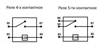
Maz 5440 and Maz 6430 are the general designations for two series of truck tractors of the Minsk Automobile Plant produced from 1997 to the present with various modifications and changes (643008, 6430A8, 643005, 6430A5, 6430A4, 631208, 6312A8, 544009, 5440A9 , 544008, 5440A8, 544005, etc.) and generations (Euro 3 4 5 6). In this article you will find a description of the most popular fuse and relay blocks Maz 5440 and Maz 6430 with diagrams and their locations.
Block in the cabin
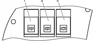
The main fuse and relay box is located in the passenger compartment, in the middle of the dashboard, on the passenger side and is closed with a protective cover.
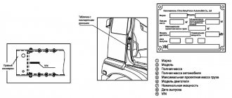
The design of the block and the purpose of the elements in them depend on the year of manufacture and the level of equipment of the MAZ. The current designation for your vehicle will be printed on the back of the protective cover. Check the purpose, and in case of difficulty, contact your dealer.
Option 1
Description of fuses
p, blockquote 8,0,0,0,0 —>
- 16A refrigerator
- 16A (+) from the lock for ABS brakes
- 16A air dryer, heaters
- 16A (+) from the generator for ABS brakes
- 16A from generator for engine electronics
- 8A turns
- 8A lights
- 8A tractor brake signals
- 8A (+) with brake signal relay
- 8A reverse light
- 8A trailer brake lights
- 8A alarm
- 8A heater control unit
- 8A thermostat timer, radio
- 8A standard heater fan
- 8A independent heater heaters
- 8A high beam right headlight
- 8A high beam left headlight
- 8A low beam right headlight
- 8A low beam left headlight
- 8A size reserve
- 8A heated mirrors, power windows
- 8A fan clutch
- 8A electrical signals
- 8A voltage regulator, engine stop
- 8A engine stop valve
- 8A switches
- 8A wiper
- 8A power supply for other indicator lamps
- 8A power supply for emergency warning lamps
- 8A power supply for devices
- —
- 8A tachograph
- 6A cabin lamps
- 6A rear fog lights
- 8A additional high beam headlights
- 8A front fog lights
- 8A right side trailer
- 8A left side of trailer
- 8A instrument lighting
- 8A right side of the tractor
- 8A left side of the tractor
Specifications
Dimensions of the car:
- length – 7250 mm;
- width – 2550 mm;
- height – 2900 mm;
- wheelbase – 3700 mm;
- ground clearance - 185 mm.
Model weight characteristics:
- permissible weight – 10100 kg;
- rear axle load – 6300 kg;
- front axle load – 3800 mm;
- curb weight – 5500 kg;
- load capacity – 4450 kg;
- weight as part of a road train - 17300 kg.
The MAZ 4371 equipment platform is quite large and can accommodate up to 30 cubic meters of cargo. For the tent version, the length is 5300 mm, width – 2480 mm, height – 2305 mm. For the on-board modification, the length is 6220 mm, width – 2480 mm, height – 536 mm.
The maximum speed developed by the truck does not exceed 85 km/h.
Fuel consumption MAZ 4371
In terms of fuel consumption, the MAZ 4371 falls within the average statistical figures for the segment. For 100 km of travel, the truck consumes about 23 liters of fuel. In winter, the figure increases slightly. The model's fuel tank capacity is 130 liters.
Overview of the MAZ 5440 electrical circuit design
A separate part is allocated to indicate light signaling and lighting equipment: flashlights, spotlights, headlights, fog lights, lighting in the cabin.
Power supply is required for instruments located on the driver's panel, as well as an audible alarm that informs about problems with pressure in the brake system.
A significant part of MAZ electrical equipment is the mounting block, which contains fuses.
The device includes a multilayer printed circuit board, and if there is a short circuit in the MAZ electrical wiring and current-conducting harnesses, the unit fails. Sometimes the unit can be repaired, but more often it needs to be replaced.
When removing and installing the unit, it is important to carefully monitor compliance with the connection rules.
Current-consuming devices should be connected in accordance with the Euro MAZ electrical diagram.
Do not forget that electrical diagram drawings do not reflect the actual location of elements.
The graphic representation shows the connection of the components with each other.
The nodes can be connected in series or in parallel, the components are located in the circuit in a certain order established by the manufacturer.