Carburetor of an internal combustion engine
See also the article about injection engines.
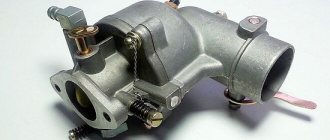
A standard carburetor has an air diffuser, which is designed as a tapering carburetor neck. The air passing through this constriction creates a reduced pressure. A hole with a small diameter through which gasoline is supplied is specially placed in this place. Ambient air pressure forces gasoline from the float chamber to exit into this hole in the air neck, then the fuel is sent to the intake manifold and then to the working area of the cylinders.
Since the engine operates over a wide speed range, it requires a different mixture composition, also in winter, when warming up, idling, in the medium speed range and under high load. Carburetors are equipped with various systems that help it do its job in various conditions. In addition to the components that will be described below, there are some components, including solenoids for stopping fuel injection and pressure drop dampers used in special cases. These parts are placed for various reasons and their removal can significantly affect the normal functioning of the engine.
Float chamber
One of the criteria for proper carburetor operation is accurate adjustment of the fuel level in the float chamber. Fuel is supplied through the fuel line channel to the float chamber. The fuel level in the float chamber is maintained using a float device with a needle valve. After filling the chamber, the float raises the needle and stops the flow of gasoline, while the displaced air is discharged through the hole provided for this purpose. The sprayer and the float chamber are communicating vessels. The fuel level in the float chamber should be slightly below the nozzle exit.
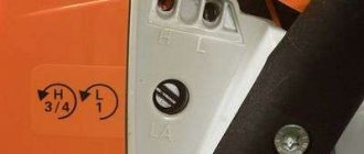
Tuning
The modernization is carried out in order to increase operating efficiency and to increase the power of the entire power unit. There are the following tuning options:
Replacing the valve needle and setting a new level in the float chamber. By performing this action, you can ensure more stable operation of the carburetor. We should not forget about preventing the appearance of an over-lean fuel mixture in high-power modes. By using a rubber locking needle, stable maintenance of a certain speed level can be achieved.
Solex carburetor disassembly diagram.
Throttle sawing. It is necessary to make the correct selection of cross-sections of the remote sensing holes, namely slightly smaller than optimal. When performing this action, CO2 emissions are reduced and gasoline consumption is reduced by approximately 2%. The idle mode will also undergo changes - there will be a more uniform division of the air-fuel mixture among the cylinders.
Diffuser polishing. This procedure is designed to reduce aerodynamic losses and increase flow speed.
There is also the option of independently upgrading the SOLEX carburetor. Its essence lies in smoothing corners, boring and grinding surfaces. The operation is carried out in the following sequence:
- dismantle and disassemble the carburetor
- separate the upper part of the carburetor from the body, clean it, rinse it and blow it with compressed air
- take out the throttle shaft and grind it off
- We disassemble and clean the lower part of the carburetor
- remove the dampers with axles
- We round the axis of the air damper
- We assemble the throttle mechanism and grind off all sharp corners and irregularities
- we install the accelerator pump tubes in both chambers
- Using sandpaper we smooth out the unevenness of the mixing chamber.
Mixing chamber
A tube-shaped nozzle installed in the mixing chamber is responsible for spraying fuel into the cavity of the carburetor. An air damper, designed to regulate the composition of the mixture, is placed in the mixing chamber above the diffuser. As it drops, the fuel ratio in the mixture will increase. Excessive obstruction of the air gap leads to over-enrichment of the mixture and termination of the fuel combustion cycle in the engine. To control the air-fuel mixture, a throttle valve is installed at the bottom of the mixing chamber on the engine side.
Diffuser
Diffuser - represents the narrowing area of the mixing chamber. The air entering the engine increases speed in the diffuser, as a result of which a vacuum is formed at the sprayer. Under the influence of this difference, fuel is supplied from the atomizer and actively mixed with the air flow. Gasoline from the float chamber enters the atomizer through a channel. A nozzle is screwed into the channel - a screw with a through hole of strictly calculated diameter and shape. The nozzle is responsible for the speed at which gasoline is transferred to the atomizer.
Suction Carburetor starter control handle
The presence of a choke (or, more correctly, a control knob for the carburetor starter) simplifies starting the engine when cold in the near-winter season, when negative temperatures lead to active condensation of the working mixture on the walls of the cylinders and the carburetor mixing chamber. The purpose of the choke is to enrich the mixture, resulting in a mixture that is significantly richer in fuel compared to the usual fuel/air ratios.
Later, many manufacturers introduced a system of automatic transition to the starting mode and back, and carburetors with automatic suction appeared. At the same time, the principle of operation of the manual start flap control system has been preserved for more than 70 years. By covering the air at the inlet to the carburetor, it ensures a more active flow of fuel from the jets and, in the end, the same enriched engine operating mode.
Unfortunately, errors are periodically found in articles; they are corrected, articles are supplemented, developed, and new ones are prepared. Subscribe to the news to stay informed.
If something is unclear, be sure to ask! Ask a Question. Discussion of the article.
How to lock a nut on a stud? Vibration-resistant mount. How to fix a threaded connection, lock the nut so that it does not unscrew.
Is the internal combustion engine faulty? Troit / double. Power drop Review of car engine faults. Troit / double. Power drop. .
Automatic gearbox. Torque converter. Robot. The design and principle of operation of a robotic gearbox, automatic transmission and torque converter c.
Automotive differential. Blocking. Self-locking. Elevated. The design and principle of operation of differentials, including locking and self-propelled ones.
What inexpensive roof rack to put on the roof of a Mitsubishi Lancer. Do-it-yourself modification of a cheap Ant rack for installation on the roof of a Lancer.
Until the mid-80s, gasoline internal combustion engines in cars and light trucks were widely equipped with carburetors. Such engines operate on the principle of combustion of a fuel-air mixture prepared in advance by an external device in the engine cylinders. The specified working mixture consists of droplets of fuel and air. The carburetor is responsible for the process that involves the formation of a mixture of these components in the required proportion for maximum efficiency of the internal combustion engine. The simplest carburetor is a mechanical metering device.
Read in this article
“Suction” of foreign air into the carburetor
When foreign air enters the carburetor, the fuel mixture entering the car's engine cylinders becomes depleted.
The share of gasoline in it remains the same, but the share of air increases significantly. Such a composition simply does not ignite or ignites with difficulty and for a short time.
Therefore, the engine may not start at all (both cold and hot), it may start and stall, unstable idling is possible, combined with the impossibility of adjusting it, as well as “failures” when starting off and in motion.
If the suspicion falls on the leakage of connections, seals and hoses, then it is necessary to check them as soon as possible.
General check for the presence of “suction” of foreign air into the carburetor
There is one effective way to check whether foreign air is being sucked into the carburetor. It is necessary to remove the air filter housing from it, start the engine, let it run for a while and then cover the top of the carburetor with your palm.
If the engine continues to operate with the air supply channels blocked, an attempt should be made to search for the location of this same “suction”.
If the carburetor stalls, look for the cause of the malfunction in something other than the “suction” of foreign air. Of course, this check does not claim to be exceptionally accurate, but in some cases it can help.
Possible places for foreign air to enter the carburetor
Check how tightly the carburetor solenoid valve is screwed in.
Or the idle air system fuel nozzle holder inserted instead.
For a number of reasons, they sometimes get twisted and even lost. It is necessary to tighten the valve or holder, and if the engine begins to operate normally, by screwing or unscrewing the solenoid valve we achieve stable idle speed.
The fuel jet holder (on some carburetors is installed instead of the solenoid valve) must be screwed in with a little force.
Solenoid valves for carburetors 2108, 21081, 21083 Solex and 2105, 2107 Ozone
It is also necessary to check whether the rubber sealing ring on the solenoid valve is damaged.
Check the presence and condition of the rubber o-ring on the fuel mixture “quality” screw.
The image shows a screw for adjusting the “quality” of the fuel mixture at idle speed of the 2107 “Ozone” carburetor with a rubber o-ring.
Screw for adjusting the “quality” of the fuel mixture of the carburetor 2105. 2107 Ozone
Check the vacuum hoses for leaks.
— From the ignition distributor (distributor) to the carburetor.
— From the vacuum brake booster to the intake manifold.
— Crankcase ventilation hose It is necessary to ensure that they are tightly seated on the fittings and that there are no cracks, cuts, punctures or abrasions.
Pinch the hoses near the carburetor fittings one by one and try to start the engine. If the air leak is blocked in this way, the engine will work normally. The image shows the location of possible “suction” of foreign air into the carburetor 2108, 21081, 21083 Solex.
Places of possible “suction” of foreign air into the carburetor 2108, 21081, 21083 Solex of VAZ 2108, 2109, 21099 cars
Check the seals under the carburetor and intake manifold for leaks.
If no gaps are visible visually and the whistle of sucked air is not audibly heard when the engine is cranked with the starter, then we try to tighten the carburetor and intake manifold mounting nuts. The tightening torque is 13 -16 N.m for the carburetor nuts, 21 -26 N.m for the intake manifold nuts. That is, there is no need to pull too hard, especially on a warm engine.
Tightening did not help, we remove the carburetor and change the gaskets, fortunately they are not expensive.
You can cover the connections being tested with soap foam or VD-40 liquid; a window will form at the point of “leakage” in the soap foam.
As a result of excessive tightening of the carburetor mounting nuts or for some other reason, the seating plane of the carburetor may be deformed and then excess air will be sucked in for this reason. To identify this defect, it is necessary to place the carburetor removed from the engine on a known flat surface, for example a sheet of thick glass, and see if there is a gap between the lower plane of the carburetor and the flat surface. There shouldn't be any gaps. There are two options: either grind the seating surface of the carburetor or put an extra gasket under it.
Article on the topic: “Eliminating deformation of the lower surface (flange) of the Solex carburetor 2108, 21081, 21083.”
More information on the topic in our VKontakte group -
Twokarburators VK , on our Yandex Zen channel - Twokarburators DZ , as well as in Odnoklassniki - Twokarburators OK
More articles on repairing and tuning carburetors
— Setting up the carburetor 2108, 21081, 21083 Solex
— The carburetor “flows”
— Operating modes of carburetors 2108, 21081, 21083 Solex and 2105, 2107 Ozone
— Increased power and throttle response of the engine with carburetor 2108, 21081, 21083 Solex
— Checking the tightness of the needle valve of the carburetor 2108. 21081, 21083 Solex
— The Solex carburetor “flows” into the second chamber
— The starting device of the Solex carburetor 21083 (2108, 21081) does not work
A little history
Early developments at the dawn of the engine building era used lighting gas as fuel. At an early stage, such engines simply did not need a carburetor. The illuminating gas entered the cylinders due to the vacuum that was formed during engine operation. The main problem with such fuel was its high cost and a number of difficulties during use.
The second half of the 19th century was the period when inventors, engineers and mechanics all over the world tried to replace expensive lighting gas with a more economical, cheaper and accessible type of fuel for the internal combustion engine. The best solution was to use liquid fuel that is familiar to us today.
It is worth considering that such fuel cannot ignite without the participation of air. To prepare a mixture of air and fuel, an additional device was required. Not only that, but it was also necessary to mix air with fuel in the required proportions.
To solve this problem, the first carburetor was invented. The device was released in 1876. The creator of an early model of the carburetor was the Italian inventor Luigi De Christoforis. In its design and operating principle, the first carburetor had a number of significant differences from more modern analogues. To obtain a high-quality fuel-air mixture, the fuel in the first device was heated, and its vapors were mixed with air. For a number of reasons, this method of forming a working mixture is not widely used.
Developments in this area continued, and a year later, talented engineers Gottlieb Daimler and Wilhelm Maybach created the design of an internal combustion engine that had a carburetor operating on the principle of fuel atomization. This device formed the basis for all subsequent developments.
Modernization
The main direction of further work of engineers was the maximum automation of all mixture formation processes. The best minds of many companies producing cars and related equipment worked to improve the design of the carburetor. For this reason, you can find a great variety of simple and complex carburetor models from numerous global manufacturers.
Reasons for airing
Where can air get into the carburetor? As a rule, this is due to loose tightening of the electromagnetic valve or holder (on some cars, instead of an electromagnetic valve, a nozzle holder is screwed in), drying out and damage to the rubber cuff of the adjustment screws, damage to the vacuum tubes and other reasons.
Let's take a closer look.
- Often, due to various reasons, EM valves are turned out and even lost. In addition, the valve makes it possible to regulate stable engine speeds in idle mode. If there is a holder, it must be screwed in to the proper depth. Finally, the EM valve has its own rubber seal, which can dry out over time. You should definitely check it out.
- Both adjusting screws are equipped with O-rings. Over time, the latter may no longer hold, and then air is sucked in from here.
- Vacuum tubes are laid from the distributor to the carburetor device, and also from the brake control unit to the intake manifold. On such a long line, yes, there are gaps, and in some places the hoses break or holes form. Thus, airing of the system occurs.
Carburetor gasket
In addition, you need to pinch the hoses one by one near the carb fittings and try to start the engine. Let's say the engine does not start due to severe air intake. By pinching the hoses, you can block the suction, which a priori will help the power plant start.
Gaskets occupy a special place in the carburetor system. They also need to be checked for leaks. If the gaps are not noticeable externally, and the sounds of suction are not audible when the starter device is turned, you need to tighten the bolts of the intake mechanism and fuel mixer, hoping that the gaskets are loose. Then check engine starting again.
By tightening torque. It is recommended to fasten the carburetor clamps with a force of 13-16 N.m, and the manifold nuts with a torque of 21-26 N.m. This means that you should not pull too much, otherwise you can easily damage the threads. It is extremely dangerous to overdo it on a hot engine.
Some experts do this. Cover the connections with VD-40 liquid or soap foam. Then they observe. If a window forms in the foam, this is where the leak occurs.
In general, you should not overtighten the nuts! Due to excessive tightening, the seating plane of the carb can easily become deformed, and then air leaks will occur for this reason.
The defect of an uneven surface is detected as follows. Place the carburetor, removed from the car, on a flat table. The plane should be completely free of grooves and bumps. It is better if it is a sheet of thick glass placed on a table. Then you need to look carefully to see if there is a gap between the surface of the carb and the glass. If yes, then this indicates deformation.
Carburetor and injector
Further in the history of fuel supply and mixture formation systems, monoinjection (monoinjector) first appeared, and fully electronic injection and high-performance fuel injectors finally replaced obsolete carburetors.
The main advantage of the injector is much more accurate and timely dosing of fuel to obtain the required proportions of the fuel-air mixture. The emergence and introduction of affordable microprocessors into the auto industry ultimately led to the fact that the need for a complex carburetor and additional devices in its design simply disappeared. All the functions of the individual elements of the carburetor were taken over by one single control unit (ECU), and simple design devices were installed in the injector design.
Today, carburetor injection is found only on those engines whose main purpose is the target installation on special equipment. The reason for this decision was the vulnerability of electronic injection systems during harsh operating conditions. Electronic components and injector modules suffer from increased humidity and contamination, and injectors are sensitive to fuel quality. As an example, it is worth saying that it is definitely better to install a mechanical carburetor on a special vehicle when using it in swamps, which will not burn out. Such a carburetor can always be easily maintained, cleaned and dried if necessary.
Types of carburetors
As we have already said, the process of modernizing carburetors has generated a large number of types of this device from different manufacturers. All this variety of carburetors can be divided into three groups:
- bubbling;
- membrane-needle-shaped;
- float;
The first two types of carburetors have practically not been seen for a long time, so we will not dwell on these designs. It is more advisable to consider a float carburetor, which can still be seen in various modifications on civilian cars of the 90s era today.
Float carburetor design
The main job of a carburetor is to mix fuel and air. Different models of carburetors carry out this process according to a similar principle. The float carburetor consists of the following elements:
- float chamber;
- float;
- float lock needle,
- jet;
- mixing chamber;
- spray;
- Venturi tube;
- throttle valve;
The float carburetor is designed in such a way that a special line is connected to its float chamber. This line supplies fuel from the fuel tank to the carburetor. Regulation of the amount of fuel in the chamber is carried out through two elements that are interconnected. We are talking about a float and a needle. A drop in the fuel level in the float chamber means that the float will drop along with the needle. Thus, it turns out that the lowered needle will open access for the next portion of fuel to enter the chamber. When the chamber is filled with gasoline, the float will rise, and the needle will simultaneously block access to fuel.
At the bottom of the float chamber there is the next element called a jet. The nozzle acts as a calibrator and ensures dosing of the fuel supply. Through the nozzle, fuel enters the atomizer. This is how the required amount of fuel moves from the float chamber to the mixing chamber. The process of preparing the working fuel-air mixture takes place in the mixing chamber.
Structurally, the mixing chamber has a diffuser. This element is designed to increase air flow speed. The diffuser is responsible for creating air vacuum in the immediate vicinity of the sprayer. This helps draw fuel out of the float chamber and also helps to atomize it better in the mixing chamber. This is the basic design of a simple float carburetor.
Throttle: cold start and idle
The amount of working fuel-air mixture that enters the engine cylinders will depend on the position of the throttle valve. The damper has a direct connection with the gas pedal. But that is not all.
Some cars with a carburetor had an additional device to control the throttle valve. This element is well known to fans of the old “classics” from VAZ. Motorists popularly nicknamed this device “suction”, and the device itself was created for cold starting. The element is made in the form of a special lever, which is located at the bottom of the dashboard on the driver's side.
The lever allows you to additionally control the throttle valve. If you pull the “choke” towards you, then the damper closes. This allows you to limit air access and increase the level of vacuum in the carburetor mixing chamber.
At increased vacuum, gasoline from the float chamber is drawn into the mixing chamber much more intensely, and the insufficient amount of incoming air forces the carburetor to prepare a rich working mixture for the engine. It is this mixture that is best suited for confidently starting a cold engine.
The operation of a carburetor engine in idle mode is as follows:
- The carburetor is equipped with special additional air jets. These jets are responsible for supplying a strictly dosed amount of air;
- the air passes under the throttle valve and is then mixed with gasoline according to the working algorithm. In this case, the entire process occurs when the gas pedal is not depressed and released;
This is what the basic device and operating principle of a float-type carburetor looks like.
The principle of operation and design of a simple carburetor
In the first device, invented by L. Christoforis in 1876, the fuel was heated, evaporated, and the resulting vapors and air flows were mixed. A year later, the solution was improved using the principle of fuel atomization, which became the basis for subsequent projects.
Before the widespread use of devices familiar to us, there were bubbling and membrane-needle models. The first were in the form of a gasoline tank, in which a board and a pair of pipes were located close to the surface for supplying a mixture of fuel and air from the atmosphere and taking it into the engine. The air moved under the board, directly above the fuel, became enriched in vapor and became a combustible mixture. It was a simple but working system. The throttle valve was located separately. The functioning of the motor with a bubbler unit was influenced by natural conditions - evaporation depended on temperature. Such a system was difficult to regulate and was explosive.
Diagram of a bubble carburetor.
The membrane-needle device is located separately from the gas tank. It contained several chambers, rigidly connected using a rod. The valve seat through which fuel was supplied was locked with a needle on the stem. The chambers were connected by a fuel channel and a mixing zone. The parameters of the device were determined by the springs on which the membranes were pressed. Such a carburetor worked regardless of street conditions and location; it was popular in the early 19th century, when it was installed on cars and motorcycles, and in airplanes with piston internal combustion engines.
Diagram of a membrane-needle carburetor.
Strengths and weaknesses of the device
The main advantage of the carburetor is its affordable maintainability. To this day, there are special repair kits on the market that allow you to return the carburetor to operation quickly enough. Repairing a carburetor does not require an arsenal of any special equipment, and almost any motorist can repair the device if they have certain skills.
A mechanical carburetor is not so afraid of dirt and water, since their entry cannot completely damage it. This simultaneously conceals both the strength and weakness of the device. The carburetor needs to be adjusted quite often and must be cleaned compared to fuel injection, but it is more durable than electronic solutions when a number of conditions arise that are considered difficult or even extreme operating conditions.
A little history. Previous types of carburetors
As soon as inventors of the second half of the 19th century began to try to equip equipment with engines running on gasoline and kerosene, they had to take into account that this fuel ignites only with the participation of air. Moreover, for the engine to operate efficiently, it is also necessary to mix air with fuel in a certain proportion.
The first carburetor was invented in 1876 by the Italian Luigi Christoforis. In his device, the fuel was heated, evaporated, and its vapors mixed with air. A year later, Daimler and Maybach found a more rational solution by applying the principle of fuel atomization. This simple and effective principle formed the basis for all subsequent developments.
Gottlieb Daimler in a car with a personal driver.
Before the widespread use of float-type carburetors, two more types of these devices were used: bubbler and membrane-needle carburetors.
Bubbler carburetors were gas tanks, inside of which, at a short distance from the surface of the fuel, there was a blank board and two wide pipes - one supplies from the atmosphere, and the second takes the fuel-air mixture into the engine. The air passes under the board, above the surface of the fuel, is saturated with its vapor, and a combustible mixture is obtained.
This is a primitive but effective design. The throttle valve was located separately on the engine. The operation of an engine with a bubbler carburetor depended on the weather outside: the degree of fuel evaporation varied depending on the ambient temperature. Some of the fuel-air mixture may have condensed. The whole structure was quite explosive and difficult to regulate.
A membrane-needle carburetor is a complete device separate from the gas tank. It consists of several chambers, which are separated by membranes and rigidly connected to each other by a rod. A needle is attached to this rod, which locks the fuel supply valve seat. The chambers are connected by channels to the mixing cavity, on the one hand, and to the fuel channel, on the other.
The characteristics of such a carburetor are determined by calibrated springs on which the membranes rest. This is no longer a primitive, but rather simple design, the advantage of which, in addition to its simplicity, is the ability to operate reliably in any position and in any conditions. Such carburetors were installed in the first half of the twentieth century not only on cars and motorcycles, but also on airplanes with piston internal combustion engines.
The third type of carburetor, which eventually became the main one in the entire global automotive industry, is a float carburetor with jets. The float carburetor, the design of which was regularly improved, eventually gained universal popularity throughout the world. It was a very versatile device and could be installed using an adapter on a wide variety of models of cars and motorcycles. Its device will be discussed in the following sections of this publication.
These carburetors, the latest generation of these devices, were installed on Nissan cars at the turn of the 80s and 90s. Their complexity lies in the large number of auxiliary devices responsible for stabilizing the operation of the carburetor in various modes (sharp release of gas, idling mode when a car with an automatic transmission is idle, leveling and stabilizing engine speed when starting the air conditioning system, etc.) . Accordingly, such a “brought to perfection” carburetor was supplemented with numerous auxiliary devices: valves, bimetallic springs, heaters, etc.
Injection systems have been invented a long time ago, but at first they were expensive for mass production of automobiles. But the emergence and widespread introduction of affordable microprocessors in the auto industry ultimately led to the fact that the need for a carburetor, even the most complex one, with solenoid valves and additional devices, simply disappeared. All functions of the individual elements of the carburetor began to be performed by a single electronic control unit (ECU), and simple design devices were found in the injector design.
How to use?
The suction disappeared with the advent of injection engine power systems. The essence of its use was as follows: when the engine was cold, the handle was pulled completely towards you. After this, the engine was started. As a rule, the revolutions rose to 2 thousand, but they could do more. Now, it was necessary to gradually remove the handle until the minimum stable speed appeared. As soon as they were more or less stabilized, the handle was removed even further, and so on until it was completely removed.
Driving a car with the choke pulled out is very, very not recommended. The problem is that it was possible to fill the spark plugs and then the engine would refuse to start at all. However, if there is not much time left until the end of its shutdown, then it was still possible to drive with a light load.
Float carburetor design
The float carburetor provides the most stable parameters of the fuel-air mixture at the outlet and has the highest performance qualities compared to previous types of these devices. By the way, the statement that an injector is definitely more economical than a carburetor is erroneous. A well-tuned float carburetor provides fuel consumption indicators similar to those of an injector, but, of course, it is not so stable in operation.
A float carburetor consists of the following main elements: float chamber; float; float shut-off needle, jet; mixing chamber; spray; mixing chamber with diffuser - Venturi tube; throttle valve. Fuel is supplied to the float chamber through a special line from the gas tank. The amount of this supplied gasoline is regulated in the chamber using two interconnected elements. This is a float and a needle.
The structure of the carburetor today
Today, float models are used, which are the most advanced. They can be seen on most cars.
Design and operation of the carburetor: 1 - adjusting screw of the starting device; 2 — lever pin 24, included in the groove of lever 3; 3 — air damper control lever; 4 — screw securing the air damper drive rod; 5 - adjusting screw for slightly opening the throttle valve of the first chamber; 6 — throttle lever of the first chamber; 7 — axis of the throttle valve of the first chamber; 8 — throttle drive lever of the second chamber; 9 — adjusting screw for the amount of idle mixture; 10 — axis of the throttle valve of the second chamber; 11 — throttle lever of the second chamber; 12 — pipe for suction of crankcase gases into the rear throttle space of the carburetor; 13 — throttle valve of the second chamber; 14 — outlet openings of the transition system of the second chamber; 15 — throttle body; 16 — sprayer of the main dosing system of the second chamber; 17 — small diffuser; 18 — fuel nozzle housing of the transition system of the second chamber; 19 — accelerator pump nozzle; 20 — fuel supply pipe to the carburetor; 21 — econostat sprayer; 22 — air damper; 23 — starting rod; 24 — air damper lever; 25 — starter cover; 26 — lever pin 24, operating from the rod 23 of the starting device; 27 — air damper axis; 28 — carburetor cover; 29 — tube with econostat fuel jet; 30 — fuel filter; 31 — needle valve; 32 — emulsion tube of the second chamber; 33 - float; 34 — main fuel jet of the second chamber; 35 — accelerator pump bypass jet; 36 — throttle valve drive lever; 37 — accelerator pump drive lever; 38 — accelerator pump diaphragm; 39 — adjusting screw for the quality (composition) of the idle mixture; 40 — vacuum intake pipe of the vacuum ignition timing regulator. 41 — carburetor housing. 42 - solenoid shut-off valve; 43 — adjusting screw for additional air for factory adjustment of the idle speed system; 44 - trigger diaphragm.
A float carburetor consists of many elements:
- Float chamber to maintain fuel at a given level.
- A float equipped with a special needle, which is used to dose the level of gasoline.
- Mixing chamber - for mixing finely dispersed fuel with air.
- A diffuser is a narrowed area to increase air speed.
- A sprayer equipped with a nozzle that connects the chambers delivers the mixture to the diffuser.
- Throttle valve - to regulate the flow of working fluid.
- Air damper - to regulate the flow of air entering the carburetor. Using the element, a “rich”, “normal” or “poor” mixture is created.
- Idle system - supplies fuel past the mixing chamber through special channels into the throttle space.
- Econostats and economizers provide additional fuel supply under significant loads. Econostats operate from air rarefaction, economizers are controlled forcibly.
- Fuel suction - for forced enrichment of the fuel mixture. Using the lever, the driver opens the throttle slightly, air passes through the mixing chamber and takes in more fuel. As a result, the mixture becomes richer, helping to start a cold engine.
Float chamber
One of the most important factors in the effective operation of a carburetor is the fuel level in the float chamber. The correct fuel level determines the stable operation of the engine at idle and at low speeds. Since the adjustment of the idle system actually determines the correct compensation of the GDS composition, operation in all other modes indirectly depends on the stability of the fuel level.
The level of gasoline in the chamber is set in such a way that in case of any deviations of the device from the vertical position, there would be no spontaneous outflow of fuel from the nozzles into the mixing chamber. To further compensate for tidal phenomena, more advanced carburetors were equipped with additional economizers, as well as parallel float chambers located on the sides of the carburetor and connected to each other by a transverse channel or a special communicating cavity. The floats in different carburetors were made by soldering from stamped brass halves, or made of plastic.
The principle of operation of the carburetor
First, the fuel is sent to the float chamber. When the required level is reached, the float rises and closes the valve through which fuel is supplied. When the float drops, the fuel supply resumes.
Next, the fuel goes into the mixing chamber, where a combustible mixture is created. Air is supplied from above, which combines with the fuel. The chamber contains a spray tube with a jet, as well as a throttle and diffuser. The jet is a plug that prevents fuel from leaking out of the float chamber. The damper connected to the pedal is called the throttle. When pressed with your foot, it opens and the combustible mixture enters the cylinder. As a result, the car picks up speed. The diffuser contains a distribution tube.
At the moment of start-up, a vacuum is formed in the mixing chamber, and fuel is sprayed from the atomizer. A flow of air rises, which, when mixed with fuel, transfers the fuel into the cylinder.
In addition to the mixing and float chambers, the newest devices also contain a starting and dosing device, an idle design, an economizer, and an accelerator pump. Outdated models do not provide full engine operation, since depending on whether the engine is cold or hot, the mixture must be different. If a cold engine is started, a fuel-rich mixture is required. In cases where the engine has been running for a long time, a mixture with a small amount of fuel is required.
To increase speed or drive in a loaded car, you need a mixture highly enriched with fuel. A similar situation occurs when driving at idle, at low speeds. A simple carburetor cannot provide such conditions.
Mixing chamber. Dosing systems, economizers, ecostats
The mixing chamber ensures that tiny drops of gasoline, this “fog,” are mixed into the passing air stream. This function is performed by a diffuser - a specially narrowed section of the chamber. Thanks to this diffuser, the air passing through it is significantly accelerated. The movement of air during acceleration in the diffuser ensures the formation of a vacuum in the spray tube. Because of this, gasoline is constantly added and mixed into the passing stream.
The engine operates in various modes during operation. Therefore, fuel-air mixtures require different compositions, including those with a sharp change in the content of gasoline vapor fractions. To prepare a mixture of different concentrations, optimal for different engine operating modes, “advanced” carburetors are equipped with dosing devices. They come into operation or turn off at different times, or work simultaneously, providing the most optimal mixture composition for obtaining the best combination of power and efficiency in all engine modes. These metering systems are based on pneumatic compensation of the fuel-air mixture.
Economizers and econostats are additional parallel systems for supplying fuel to the mixing chamber. They enrich the air-fuel mixture only at high vacuum levels (i.e., close to maximum loads), when an economically generated mixture cannot meet the engine's needs. Economizers are equipped with forced control, pneumatic or mechanical.
Econostats are simply tubes of a certain cross-section, in some cases with emulsion channels, led into the space of the mixing chamber above the diffuser - into the zone where vacuum appears at maximum loads.
Mechanical fuel leak
Not saturation, but simply the amount of working fuel-air mixture that enters the engine cylinders depends on the throttle position. This damper is directly connected to the gas pedal in the cabin. Connoisseurs of the old VAZ “classics” are also familiar with another device for controlling the throttle valve. This is a “suction” for cold starting the engine - a mechanical “suction” lever for fuel, at the bottom of the dashboard. If you pull the “choke” towards you, the damper closes.
This limits the access of air and increases the level of vacuum in the carburetor mixing chamber. At increased vacuum, gasoline from the float chamber is drawn into the mixing chamber much more intensely, and the insufficient amount of incoming air makes it possible to prepare an enriched working mixture for the engine, which is more suitable for starting a cold engine.
Principle of operation
It is very difficult for a cold engine to start on a conventional air-fuel mixture. To alleviate this suffering, it was necessary to enrich this mixture.
To do this, a manual choke was installed in the carburetor, which was connected to a handle in the cabin using a cable. With the handle fully pulled out, the valve is closed, the mixture is rich. That is why it was possible to flood the candles. When we remove the handle, the damper opens, gradually normalizing the mixture.
We recommend reading: How did I fill 22 liters of AI-95 for 100 rubles? Sharing a secret
Classification of carburetors
- In the direction of flow of the fuel-air mixture - vertical and horizontal.
- According to the method of adjusting the nozzle cross-section and the formation of vacuum - with constant vacuum (the newest and most advanced carburetors made in Europe and Japan); with a constant nozzle cross-section - all serial carburetors up to the latest generations of these devices, including all those mass-produced in the USSR; with spool throttling - for the most part, horizontal carburetors for motorcycles, in which, instead of a throttle valve, the amount of mixture supplied is controlled by a slide valve.
- According to the number of mixing chambers – single-chamber and multi-chamber. It makes sense to use “double” carburetors, for example, on engines where the cylinders are located quite far from each other. Then each half injects the fuel-air mixture only into “its” cylinders. In addition to “paralleled” two- and four-chamber carburetors, there were also serial three-chamber carburetors (for example, “K-156” for the 3102 Volga). The 1st and 3rd mixing chambers were working in parallel here; they supplied the mixture to the 2nd – “pre-chamber”.
Adjusting the air damper drive of the carburetor 2108, 21081, 21083 Solex
To ensure a confident start of the engine and its subsequent normal operation, correct adjustment of the carburetor air damper drive (“choke”) is necessary.
If it is adjusted incorrectly, for example, due to the fact that the air damper does not close completely, the car engine may not start at all. If the air damper does not open completely, this immediately affects the increase in fuel consumption; in addition, it becomes almost impossible to adjust the idle speed.
Adjustment Tools
Open-end wrench (8mm) 2 pcs.
Checking the operation of the damper drive
— Remove the air filter cover
— Fully pull out the carburetor choke control handle (“choke”)
We look at the carburetor from above. The air damper must be closed. There should be no gaps between its edges and the walls of the mixing chamber.
The air damper of the carburetor 2108, 21081, 21083 Solex is completely closed
— Fully recess the “choke” handle
The damper should be strictly vertical.
The air damper of the Solex carburetor is completely open (the “choke” handle is pulled out all the way)
If the air damper does not close completely or does not open completely, it is necessary to adjust its drive.
Preparatory work
— Remove the air filter housing from the carburetor.
Removing the air filter housing on the VAZ 2108 engine
Adjusting the air damper drive (“choke”)
We completely recess the “choke” handle.
Thus, we open the carburetor air damper.
Loosen the locking screw of the drive rod end on the choke control lever.
Use one 8mm wrench to hold the screw bushing, and use the other to loosen the screw.
Loosen the screw of the rod sheath clamp.
Parts of the air damper drive of the carburetor 2108, 21081, 21083 Solex
We make sure that the “choke” handle is recessed all the way.
Turn the air damper control lever by hand until it stops.
As a result, the air damper should close completely, blocking the cross-section of the first chamber.
The choke control lever is turned counterclockwise until it stops
Set the distance between the edge of the rod shell and the angle of the lever to 10 mm.
10 mm gap between the edge of the choke control lever and the edge of the drive rod shell
Turn the choke control lever back clockwise.
The air damper is fully open and in a vertical position.
The choke control lever is turned clockwise until it stops
Tighten the shell clamp screw and the rod locking screw.
There is no need to use too much force when tightening, as this can crush the shell and make it difficult to move the rod. Before tightening the locking screw, push the end of the rod all the way to the right, inside the shell.
By pulling out and pushing down the “choke” handle several times, we make sure that the damper opens and closes completely. To more clearly fix the position of the air damper, after making the adjustment, you can loosen the fastening of the rod shell and move it (the shell) a couple of millimeters towards the air damper control lever. Then tighten it again.
After completing the adjustment, if necessary, adjust the idle speed (Ozone, Solex).
Notes and additions
In case of difficulty moving or jamming during movement of the air damper drive rod handle, or incomplete opening of the air damper, it is necessary to establish the reason for this.
We disconnect the rod from the lever and try to move the handle. If movement occurs freely, then the reason is most likely in the lever. If not, then change the drive rod assembly.
You should also wash the outside of the carburetor (at least from the lever side), remove the lever, inspect it for deformation, and check the condition of its retaining ball. Defective parts must be replaced.
With the choke drive lever removed, use a file to sand off the casting on the carburetor cover to which it is attached.
More details about the modification and normalization of the parts of the air damper drive of the carburetor 2108. 21081, 21083 Solex of VAZ 2108, 2109, 21099 cars are presented on the pages “Refinement of the air damper drive of the carburetor 2108, 21081, 21083 Solex” and “Carburetor choke does not work” Solex."
More information on the topic in our VKontakte group -
Twokarburators VK , on our Yandex Zen channel - Twokarburators DZ , as well as in Odnoklassniki - Twokarburators OK
More articles on the website on adjusting the carburetor 2108, 21081, 21083 Solex
— Adjusting the throttle valve drive of the first chamber of the carburetor 2108, 21081, 21083 Solex
— Adjusting the throttle valve drive of the second chamber of the carburetor 2108, 21081, 21083 Solex
— Adjusting the fuel level in the float chamber of the carburetor 2108, 21081, 21083 Solex
— Adjustment of the cable drive of the throttle valves of the carburetor 2108, 21081, 21083 Solex
— Adjustment of the carburetor starting device 2108, 21081, 21083 Solex
Advantages and disadvantages of using carburetors
The advantages of carburetors include the high homogeneity of the mixture at the outlet; low cost and technological accessibility during production; comparative ease of maintenance and repair, maintainability without the need for special equipment. Unlike an injector, which requires electrical power, the operation of a carburetor occurs solely due to the energy of the air flow sucked in by the engine.
The main reason for the displacement of the carburetor from the automotive power system was the inability to provide a fuel-air mixture of an individual composition for each of the outbreaks. And the injection system with distributed injection operates in exactly this way, stably ensuring economical and environmentally friendly engine operation.
5 / 5 ( 1 voice )
Examination
There is one very effective way to check the tightness of the carb. It is carried out after unstable engine operation is detected.
Air filter on carburetor
You need to remove the VF, start the engine and let it run for a while like this, without a filter. Then cover the top of the carb tightly with your hand. If the internal combustion engine continues to operate, then there is suction. If the engine stalls, the cause of unstable operation must be looked for in something else.