Ural M 72 technical specifications
Total information
Motorcycle type: with sidecar. Wheelbase, mm — 1430. Ground clearance, mm — 130. Track, mm — 1100
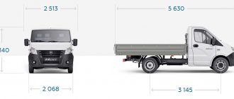
Dimensions, mm: — length — 2420; — width — 1650.
Height (by ignition key) - 1000
Motorcycle weight, kg: — dry — 335; - worker - 380.
Fuel consumption on the highway, l/100 km - 7. Fuel reserve on the highway, km - 310. Highest speed, km/h - 85.
Capacity (oil), l: - engine crankcase - 2.0; — gearbox housing — 0.8; — reverse gear housing — 0.150; — air purifier — 0.2.
Fuel tank capacity, l - 22.
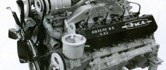
Engine
Engine type: four-stroke two-cylinder. Brand - M-72M. Cylinder diameter, mm - 78. Piston stroke, mm - 78. Working volume, cm³ - 746. Compression ratio - 5.5 ± 0.2. Maximum power, l. With. — 22. Maximum torque, kg m — 4.0. The block head material is aluminum alloy. The head gasket is asbestos metal 0.6 mm. The piston material is aluminum alloy.
Valve distribution phases (according to the angle of rotation of the crank), degrees: - beginning of intake to c. m.t. - 76; - end of intake after n. m.t. - 92; - beginning of release BC m.t. - 116; - end of release after c. m.t. - 52.
Carburetor - Two K-37.
Power transmission M-72 M
The final drive ratio is 4.62. The clutch is a dry double-disc clutch in the engine flywheel.
Number of disks: — leading — 3; — slaves — 2.
Number of springs - 6.
Technical characteristics of the M-72 M gearbox
Type - four-stage two-way.
Gear ratios: — in first gear — 3.6; — in second gear — 2.286; — in third gear — 1.7; — in fourth gear — 1.3.
Total gear ratio: - in first gear - 16.65; — in second gear — 10.56; — in third gear — 7.85; — in fourth gear — 6.01.
M-72 M motorcycle tires and their characteristics
Size, in inches - 3.75-19.
Pressure, kg/cm²: — front wheel — 1.6; — rear wheel — 2.0; - stroller wheels - 1.8; — spare wheel — 2.0.
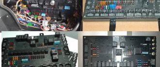
Ignition and Electrical Equipment M-72 M and their characteristics
Type - battery magneto. Ignition coil brand - B - 2B or B-11. The battery is 3MT-14. Generator - G - 11A. Relay regulator - PP-31. Signal - C - 23B. Headlight FG - 6.
Return to contents — ↑
Ural 6x6 in 10th scale.
The idea of this model was incubated for a long time, I couldn’t decide on the size, or something else. As a result, the project took 7 months. And so I found a suitable drawing, asked a friend to scale it, took it to the printing house, where they printed out all three types on whatman paper for me. The drawing was posted on the wall for convenience. I bought plastic (foamed PVC) 3mm thick. Well, a couple of tsacrine glues, thicker and thinner. HobbyKing Super Cyanoacrylate Adhesive (50g / 1.7oz) Viscous. Product https://www.parkflyer.ru/product/7174/ HobbyKing Super Glue CA (50g / 1.7oz) Product https://www.parkflyer.ru/product/7173/ And away we go. Since this is the first model built with my own hands, it was decided to start slowly, the base of the cabin, the radiator grille.
Then I decided to start the hood, because if the hood does not fold, then the hands are hooks and there is no point in continuing. But after a week of crafts and alterations, something similar came out.The hood honestly blew my mind. Further simpler. The hood is mounted on hinges Hatch Hinge 27×10.5mm (10pcs) Product https://www.parkflyer.ru/product/8230/ Doors Ultra-light pin hinges L2.5xW10xD43mm (10pcs) Product https://www.parkflyer.ru/product /9629/ But then I cast on a lot of different loops.
Then I started thinking about the frame because... There were suspicions with the steering of the wheels; under the wings the cabin seemed too wide. I made it into a rough frame. And I was right, I had to narrow the lower part under the wings.
Then a two-speed transmission from Traxxas summit arrived, I knew that it was very reliable, not by hearsay, since I had this model. Stuck it on the frame.
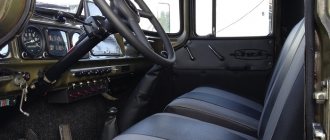
Meanwhile, I was slowly making a little salon and mirrors.
Gearbox handles, transfer cases, lowering gears.
Rubber bands for handles, by the way, these are seals for rods from ship models. Next, I began to work closely on the frame and front and rear suspension. The springs were made from a construction spatula, cut, bent, and drilled where necessary. I chose the bridges not for the sake of copyability, but they are very reliable, since the model was not meant to be a shelf model, but for trophy rides in the mud, mountains and other difficult landscapes. Axial SCX10 bridges, studs are all made from cleaned 2mm and 3mm welding electrodes, then we cut the threads and bend them where necessary. I ordered the cardans from JunFac from the CC01 chassis; according to my calculations, their dimensions suited me. Power, on the advice of knowledgeable people, was ordered a Holmes Hobbies collector regulator called brxl, and a blue motor with 45 turns, high-torque and moderately high-speed. Handout from Misha Holodilnik, from the well-known forum.
In the meantime, footrests were made from a sheet of metal tiles 0.6 mm thick. Cut it out, tried it on, then punched it with a core, not quickly.
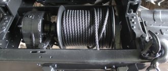
Then the question began to rest on the wheels, but after an unsuccessful fitting of 1.9-size wheels, it was decided not to save money and buy normal tires. In general, the wheels are size 2.2, with an outer diameter of 120mm. I had to think a lot about the optics. The head light fits well out of two sets. Turnigy High Power Headlight System Product https://www.parkflyer.ru/product/1486354/ Both glass and grilles LED headlights for trophy cars (made of stainless steel). Product https://www.parkflyer.ru/product/989644/ The double-sided turn signal was made from Chinese caps from car pressure meters 1:1. This cap has a separator installed and everything is painted silver, close to chrome, so that the diodes do not expose each other. And the dimensions on the roof and repeaters were cut out of caps from orange fountain pens. The rear optics were made from bicycle reflectors. Next, the rear winch was installed as on the original. I made the winch from an old half-dead XP DS1015 servo machine, after some manipulations it worked as it should. As a result, the winch pulls the Urals even with locked wheels, in general, it’s even more stupid than we would like. And the moment of preparation for painting was approaching. Well, it turned out to be the simplest thing, I took it to the body shop where a painter I knew worked and explained that I needed Multikam camouflage. Yes, the photos of working with the kung were lost somewhere, but there’s nothing special there, a square is just a square.
While the Ural was being painted, I got confused with the wiring. It took a week and 20 meters of wires and probably a dozen resistors. And this light unit, Hobbyking Professional 4 Channel Lighting System for Trucks and Cars, came up well Product https://www.parkflyer.ru/product/1191642/ If you take it, keep in mind that for full-fledged work you need a full-fledged 4-channel equipment, not less.
In the meantime, I went to the paint shop and saw something that I thought, well, I don’t know what to call it, but I was pleased to say the least.
Then I started collecting and testing all this beauty. This is what happened.
Well, I put Schwartz there for fun. After several trips, the commutator brushes were worn out twice, I realized that I needed to change the power one, since there was enough traction, but it was hard for him, and it was not very convenient to constantly change the brushes. In general, I installed a b.k., MMR regulator + tenshok 17.5t motor, there was little traction, I also had to replace the transfer case with a GP such that it was 1.8: 1, previously it was 1: 1. And oh joy and traction and lasting strength. Photo of the last handout.
Well, at the request of workers, a couple of videos featuring RC Ural 6x6. Thanks to everyone who read, to be continued, Gas 69 is currently under construction.
Engine m 72
The engine of the Ural M 72 motorcycle is a two-cylinder, four-stroke engine; according to its design features, it can be classified as a forced road-type engine (despite the lower valve timing mechanism), since its compression ratio, speed and power are quite high. The engine on heavy motorcycles from the Irbit plant has an opposite arrangement of cylinders in a horizontal plane, which ensures good balancing of the inertial forces of the crank mechanism and reliable cooling. A gearbox is attached to the engine, connected via a clutch.
The cylinders are cast from alloyed or modified cast iron. The valve boxes are cast integrally with the lower cylinder support flanges. The left cylinder is moved slightly forward in relation to the right one. The cylinder heads are cast from aluminum alloy and have double ribbed bottoms for better cooling of the cylinders of the Ural M 72 motorcycle engine. An asbestos-metal gasket is installed between the head and the cylinder.
The pistons are cast from a special aluminum alloy, which contributes to their better cooling. Two compression rings are installed in the upper grooves of the pistons. In the lower groove there is an oil collection ring. The lower groove has through cutouts designed to reduce heat transfer from the head to the piston skirt and to remove oil removed by the oil collection ring from the cylinder walls. The piston rings are made of special cast iron. All rings have straight locks, the gap in which in the working position is 0.25-0.45 mm.
The connecting rods have one-piece heads. Bronze bushings are pressed into the small heads, and single-row roller bearings with cages are inserted into the large ones. The small head is connected to the piston using a floating piston pin. The rollers of the large head roll along the surface of the crankshaft journal, which has two elbows with crank radii of 39 mm. The crankshaft assembly with connecting rods is an integral unit, since its disassembly and reassembly is impossible without special tools.
The durability of this unit is guaranteed by the factory within 15,000 km. When assembled, the shaft is installed in a one-piece crankcase on two ball bearings. To mount the engine to the motorcycle frame, there are special bosses with holes for through bolts in the lower part of the crankcase.
Motorcycle engine M 72 (disassembled). 1 — front crankcase cover; 2 — breather tube; 3 - lock nut; 4 — camshaft oil seal; 5 — oil seal body; 6 — distribution head cover; 7 — breather; 8 — camshaft gear; P - camshaft; 10 — camshaft flange; 11 — camshaft bearing; 12 - sealing gasket; 13 — camshaft bushing; 14 - crankcase; 15 — generator gasket; 16 — generator gear; 17 — connecting rod; 18 — oil pump drive gear bushing; 19 — gear; 20 — gear plug; 21 — generator stop; 22 — valve box cover and gasket; 23 — cover screw; 24 - flywheel; 25 — flywheel pin; 26 — lock washer and flywheel mounting bolt; 27 — bolt and lock washer of the crankshaft gear; 28 — crankshaft gear; 29 — bearing housing cover; 30 - bearing; 31 — bearing housing; 32 - crankshaft; 33 - oil catcher; 34 - sealing gasket; 35 — rear crankshaft bearing housing; 36 — oil seal; 37 — roller bearing separator of the large connecting rod head; 38 — roller; 39 — connecting rod; 40 — connecting rod small head bushing; 41 — piston pin; 42 - piston; 43 — oil scraper ring; 44 - compression ring; 45 — oil line pipe; 46 - defoamers; 47 — crankcase spacer; 48 - sealing ring; 49 - plug; 50 - coupling; 51 — oil pump housing gasket; 52 — oil pump housing; 53 — oil pump gears; 54 — oil pump housing cover; 55 — oil pump filter; 56 - pallet; 57 — pan sealing gasket; 58 — drain plug and sealing washer; 59 — cylinder gasket; 60 — left cylinder; 61 — carburetor gasket; 62 — cylinder head gasket; 63 — cylinder head; 64 — cylinder head mounting bolt; 65 — upper valve spring plate; 66 — valve spring sealing gasket; 67 - valve; 68 — valve spring; 69 — lower valve plate; 70 - cracker; 71 — bolt and locknut of the pusher; 72 — pusher guide; 73 — pusher; 74 — pusher guide bar; 75 — strip pin.
Return to contents — ↑
Motorcycle engine lubrication system Ural M 72
Motorcycle engine lubrication Ural M 72 has a combined lubrication system. The engine is powered by two caburators. The bearings of the large connecting rod heads, the left cylinder and the timing gear are lubricated under pressure. The remaining parts are lubricated by spraying oil with oil mist. The lower part of the engine crankcase is covered with a stamped steel pan, which is a reservoir 19 for oil, the capacity of which is 2 liters.
The Ural M 72 motorcycle engine is lubricated under pressure using a single-stage gear pump 1, driven from the engine camshaft. When the engine is running, gears 2 and 3 drive oil into the main oil line, and from there to two oil catchers 12, to the upper wall of the left cylinder and to the crankshaft drive gear. After this, the oil is sprayed onto the rubbing surfaces of the parts of the crank mechanism and the gas distribution mechanism. A spool breather is mounted in the distribution box housing, rotating together with the camshaft gear and designed to reduce oil pressure in the motorcycle engine crankcase.
Return to contents — ↑
Motorcycle engine power supply Ural M 72
The engine power system of the Ural M 72 motorcycle includes a fuel tank with a capacity of 22 liters, a three-way valve KR-16 and two carburetors K-37 A, which have one common air cleaner, suction and exhaust pipes. Carburetors have the same design, but are not interchangeable (left and right).
The K-37 A carburetor consists of a body, with which the float chamber is cast in one piece. The latter is closed by a lid 3, in which there is a drowner 5. When you press the drowner, the float lowers, the fuel level in the chamber rises, and the mixture entering the engine cylinders is enriched. The power system prepared the motorcycle engine for starting.
To automatically regulate the fuel level in the float chamber, there is a shut-off needle 4, controlled by a hollow float 6. Fuel enters the float chamber until the float floats up together with the shut-off needle, and the latter, with its upper conical end, closes the fitting hole in the float chamber cover . The fitting has a mesh filter 8, designed to filter fuel.
There are two holes at the bottom of the case. The nozzle 10 is screwed into the upper hole, into which, in turn, the main jet 9 is screwed. The fitting 7 with filter 8 is screwed into the lower hole. The nozzle communicates with the mixing chamber through an air channel.
Low speed (idle) jet 13 is screwed into the lower part of the carburetor body. The nozzle is closed from below with a locking screw 21, which is intended for purging the nozzle. Fuel is supplied to the low-speed jet from the float chamber through channel 14, and air is supplied from the air pipe through air channel 16 and an additional channel connected to air filter 17. Air channel 16 is closed by adjusting screw 18 with a lock nut.
Above the sprayer there is a throttle valve 2 with a needle 12 and a spring 23. The valve has a bevel on the side of the air entering the pipe, and on the side surface there are two longitudinal grooves.
The throttle needle enters the internal channel of the main jet nozzle, due to which fuel flows to the nozzle through the annular gap between the wall of the nozzle channel and the needle. There are four holes at the top of the needle. If you combine these holes alternately with two holes in the spool housing, you can get eight different height positions of the needle.
The lower the needle is, the poorer the mixture, and vice versa.
The throttle spool moves along a guide, which is closed on top by a cover 24 and secured with a union nut 25. Spring 23 presses the spool down, and the upward movement of the spool is limited by stop 20. This stop (limiter) during the break-in period does not allow the engine to be given high speeds and overloaded.
Throttle spools are raised or lowered by rotating the throttle knob, which is connected to the spools using cables, in the appropriate direction. Both spools must be actuated and work synchronously, which is achieved by a certain installation of the stops of the cable sheaths 26, followed by tightening the locknuts 27.
Return to contents — ↑
The gas distribution mechanism of the Ural M 72 motorcycle engine
The gas distribution mechanism of the Ural M72 motorcycle engine has a lower (side) valve arrangement.
The camshaft is mounted in the upper part of the crankcase on two bronze bearings (manufactured before 1955). On later motorcycles, the front bronze bearing was replaced by a ball bearing.
The camshaft receives drive from the engine crankshaft through a pair of helical gears.
Five cams are integral with the shaft: two suction, two exhaust and one ignition cam.
The latter serves to open the breaker contacts.
The lifting of the valves during operation of the gas distribution mechanism of the Ural M 72 motorcycle engine is carried out through rectangular flat pushers made of cast iron with bleached working surfaces.
The pushers move in aluminum guide bushings.
Reliable engine operation is guaranteed if there is a thermal gap between the pushrod bolts and the valve stems. This gap for a cold engine should be 0.1 mm.
Return to contents — ↑
Cabin, empennage and platform
Cabin
The car cabin is closed, three-seater, with a blind wind window and thermal insulation, located behind the engine, equipped with rear-view mirrors on the left and right sides. Adjust the spherical mirrors to ensure visibility areas through them according to Fig. 95 with the mounting bolts of the holders and mirrors loosened, then securely fasten them.
Rice. 95. Visibility zones through the exterior rear-view mirrors: 1, 3 — rear-view mirrors (left, right); 2 — driver’s eye point; 4 — visibility zone of the road surface; 1 - horizon line
The cabin is attached to the car frame at four points on rubber pads. When the frame is deformed, the elastic fastening protects the cabin parts from overstress. The cabin doors are equipped with locks and power windows. When closing the door, the pawl 12 (Fig. 96) of the lock comes into contact with the door latch 11 and, turning, locks the door. In this position, the pawl is fixed by latch 13 and latch 14. At the same time, the upper guide pin 9 of the lock fits into the groove of the latch and protects the door from sagging. The door lock drive handles must be positioned horizontally and directed forward. Door locks can be blocked from opening from the outside by turning the inner lock drive handle down. When the lock is locked, the lock lever 5 stops the latch, preventing it from disengaging with the latch. The left door lock can also be locked from the outside with a key.
Rice. 96. Door lock: 1 - drive housing; 2 — drive spring; 3 — drive bracket; 4 - roller; 5 - leash; 6 — outside door handle; 7 — button; 8 — retainer block; 9 — guide pin; 10 - bolt; 11 — door lock (installation); 12 - dog; 13 - latch; 14 — latch lock; 15 - spring; 16 — pawl axis; 17 — latch axis; 18 — drive rod finger; 19 — drive rod; 20 — drive ratchet; 21 - drive axis
Open the door lock by turning the lock drive handle up or by pressing the button on the outside handle. In this case, the latch releases the latch and the pawl, under the action of spring 15, returns to its original position. The door lock is secured to the lock post with two bolts and a screw, allowing it to be adjusted in height and depth. When adjusting, ensure that the lock pin 9 fits correctly into the lock groove 11. If the height of the lock is adjusted correctly, the door should not fall or rise when opening. Adjusting the depth allows you to achieve a tight fit of the lower protrusion of the latch to the pawl 12 and at the same time avoid excessive force when closing the door. Adjust the depth with the expectation of minimal deformation of the door seals, ensuring sufficient tightness and no knocking of the doors when the car is moving. If the door closes too tightly, pull the latch outwards, and when the door knocks, move it inside the cabin. The doors must be tightly closed while the vehicle is moving. If door seals are damaged, glue them with 88NP glue, having previously cleaned the surfaces to be glued with emery cloth and wiped them with a clean cotton rag soaked in gasoline. The door windows are equipped with sliding and turning glass. The door windows are raised and lowered using lever-type lifting mechanisms. The glass should move freely in the guides, without jamming. When disassembling, lubricate all rubbing surfaces of parts of locks, window regulators, hinges, fasteners, and spring axles with Ligol-24 lubricant or grease. Windshield washer and wiper. The cabin is equipped with windshield washers and a pneumatic windshield wiper. The cabin windshield wiper is included in the vehicle's pneumatic system. It consists of a pneumatic motor with a spool valve and a mechanism for laying brushes along the lower edge of the glass, two brushes, rods and brush drive levers. The windshield wiper is turned on by turning the tap head located on the instrument panel counterclockwise. 4 By rotating the tap head, you can adjust the speed of the wiper blades. When the tap head is rotated counterclockwise, the intensity of the brushes increases. When you turn the tap head clockwise until it stops, the wiper turns off. When the windshield wiper is turned off, the blades are automatically positioned along the lower edge of the glass. If the brush placement mechanism does not work, turn it on again and turn off the tap. On the left side of the hood there is a windshield washer reservoir with a pump and electric motor. Tank capacity 2 l. The washer fluid is supplied to the glass through hoses through two nozzles. The washer fluid is supplied by pressing the windshield washer control button located on the instrument panel to the left of the steering wheel. At ambient temperatures above plus 5 °C, filtered water is used to fill the tank. At temperatures from plus 5 °C to minus 40 °C, it is recommended to use a solution of distilled water and a solution of sulfanol in isopropyl alcohol (NIISS-4 liquid) TU 33.10230-76 in the proportions indicated in the table. 10. Do not use NIISS-4 without diluting it with water, since the combined action of the concentrate, atmospheric pollution and ultraviolet radiation causes changes in the paintwork of the car. Wash the windows while turning on the windshield wipers. Change the direction of the liquid stream by turning the guide in the nozzle. Cabin heating
The cabin is heated by air heated in the heater, which is included in the engine cooling system. The flow of air from outside to the heater radiator is regulated using cover 12 (Fig. 97) of the outer hatch and from the cabin with cover 7 of the inner hatch. When the heater fan is turned on, the heated air enters the air heating distributor 3, from where it is distributed throughout the cabin through controlled dampers. Table 10 Concentration of the NIISS-4 aqueous solution depending on the ambient temperature
| Ambient temperature, 0 °C | Composition by volume in parts | |
| NIISS-4 | Water | |
| Up to +5 | 0 | 10 |
| +5 to -5 | 1 | 9 |
| -5 to -10 | 1 | 5 |
| -10 to -20 | 1 | 2 |
| -20 to -30 | 1 | 1 |
| -30 to -40 | 2 | 1 |
Rice. 97. Diagram of operation of the cabin heater and windshield blower: 1 - warm air supply pipe for blowing windshields; 2 — external hatch drive handle; 3 — air heating distributor; 4 — lever for driving the dampers of the air heating distributor; 5 — lever for driving the internal hatch; 6 — electric motor with fan assembly; 7 — internal hatch cover; 8 — heater radiator; 9 — drainage pipe from the heating radiator; 10 - water supply pipe; 11 — faucet; 12 — outer hatch cover; 13 — deflector
The flaps are controlled by lever 4. When the lever is in the upper position, air flows through the deflectors 13 to blow the windows; in the lower position, air flows to warm the feet of the driver and passengers. When the position of the lever changes relative to the extreme positions, the amount of air supplied to blow the windows and heat the feet of the driver and passengers changes accordingly.
The cover 7 of the internal hatch is controlled by lever 5. In the upper position of the lever, the hatch is open, in the lower position it is closed. The optimal option for the position of the heating controls: simultaneous intake of air from the outside through the hatch, adjusted by lid 12, from the cabin through the internal hatch, closed by lid 7, and supply of heated air to the windshields, legs of the driver and passengers by setting lever 4 to the middle position. The fan switch is located on the instrument panel. Tap 11, located on the right water pipe of the engine, must be open during operation at subzero air temperatures. In the summer, the heater must be disconnected from the cooling system by closing tap I. If water is used as a coolant at subzero temperatures, the heater tap should be closed before filling the cooling system to prevent cold water from entering the heater radiator and freezing. The cabin is ventilated through the hatches of the heating system, openings of the rotary and sliding glass doors. If natural ventilation of the cabin is insufficient, open the external hatch and turn on the fan. The driver and passenger seats are separate, the shock-absorbing element is rubber belts and sponge rubber. The driver's seat can be adjusted forward or backward. Software adjustment limit mm. Using handle 2 (Fig. 98), located on the left side of the stand, the seat is fixed in the desired position. The driver's seat has a mechanism for changing the tilt of the cushion and the seat height position with an adjustment limit of 80 mm. To change the height position of the seat, unscrew the two front screws 1 on the left and right sides of the seat. Having established the required height of its front part, tighten the screws a few turns, but not tightly, loosen the fastening of the rear part of the seat by unscrewing two screws 3 by four to five turns. Once the seat position is fully adjusted, securely fasten the screws. The conical part of the screw must be fixed in one of the five conical recesses.
Rice. 98. Driver's seat: 1, 3 - screws for adjusting the seat height and tilt; 2 — handle for moving the seat forward or backward; 4 — wing nut for adjusting the backrest tilt
The driver's seat backrest has an adjustable tilt angle. To change the angle of the backrest, unscrew the nuts 4 on the left and right sides of the seat two or three turns and, having selected the desired position of the backrest, tighten them securely again. Plumage
For ease of engine maintenance and repair, individual plumage units are made detachable. The tail is attached to the vehicle frame through a rubber support pad, and to the cabin through rubber buffers. Alligator-type hood with 90° opening angle. Platform
Car platform Ural 4320-10 Ural 4320-31, Ural 4320-0911-30 with one folding tailgate. The general view and fastening elements of the platform to the frame are shown in Fig. 99. The platform is equipped with seats for transporting people, add-on grilles for the front and side sides and awning arches with struts. The middle seat can be dismantled and secured to the front side (Fig. 100), the side seats can be folded to free up space when transporting cargo. The car is equipped with a platform awning. The awning in its installed position is shown in Fig. 101. The procedure for laying the removed awning is shown in Fig. 102. The awning must be dried before installation. The platform of the Ural 43202-10 and Ural 43202-30 cars is wooden, with three folding sides. The side boards in the middle part are connected by a tie of two chains. Car platform Ural 4320-0911-10 Ural 4320-0917-30 wooden, lattice sides, non-folding, easily removable.
Rice. 99. Fastening the platform to the frame: 1 — awning arches in transport position; 2 — stepladders; 3 — bracket for fastening the platform to the car frame; 4 — side extension board; 5 — side board; 6 — tailgate locking chain; 7 — front extension board; 8 — front middle seat mounting bracket; 9 — front side; 10 — side platform seats; 11 — mounting brackets for the rear middle seat; 12 — rear side; 13 — driver signal button; 14 — platform middle seat; a - rear view
Rice. 100. Laying out the middle seat: 1 - middle rear seat; 2 — fastening belt; 3 — middle front seat; 4 — front platform grille; 5 — front platform side
The platform is equipped with removable, interchangeable side 2 (Fig. 103) and rear 4 sides, which are connected to each other using special brackets 3. When transporting pontoons, the side and rear sides must be dismantled. On the side frames of the platform base there are places for securing the transported goods.
Rice. 101. Platform with an awning: 1 — rope for fastening the awning; 2 — canopy fastening rope; 3 — awning arc; 4 — arch spacer pipe; a - front view
Fig. 102. Method of laying the awning; I - VIII - sequence of laying the awning
When operating the vehicle, periodically check the bolted connections of the cabin parts, tail, platform and their fastening to the frame; If cracks are found in parts, weld them and paint them.
Rice. 103. Platform of cars Ural 4320-0911-10 and Ural 4320-0917-30: 1 - front side; 2 — side board; 3 - bracket; 4 — rear side; 5 — bracket for fastening the mounting blades; 6 — mudguards; 7 — bracket for fastening the platform to the frame; 8 — basket for fastening canisters; 9 — stepladder; 10 — tool box
If it is necessary to carry out welding work, remove the old paint layer from the surfaces of the parts. Before touching up damaged areas (mechanical damage, cracks, chips, rust, welding soot, splashes), the old paintwork must be cleaned with fine-grained or waterproof sandpaper.
Wipe the cleaned surface with a rag soaked in gasoline or solvent, dry it and paint it with a spray bottle or soft brush with enamel of the same color in two layers, waiting for 5-10 minutes. Periodically remove and dry the cabin floor mat, as a damp mat loses its thermal insulation properties and contributes to corrosion of the cabin floor.
Controlling a motorcycle Ural M 72
The Ural M 72 motorcycle is controlled by mechanisms located on the steering wheel and having a manual drive.
In addition, there are a pair of brake pedals and a gear shift lever.
Manual control mechanisms include: throttle handle, front brake lever, clutch lever, combination shifter.
The gas handle, located on the right half of the steering wheel, is connected to the carburetors using flexible cables. To increase the engine speed, you need to turn the throttle towards yourself, and to decrease it away from you.
The front brake lever is hinged on a bracket on the right side of the steering wheel and connected to lever 24 by a flexible cable. To brake the front wheel, the front brake lever must be pressed against the steering wheel handle.
The clutch lever is located on the left handlebar and is connected to the clutch lever 19 using a flexible cable. To disengage the clutch, the clutch lever should be pressed against the steering wheel handle.
The combined shifter is designed to force the ignition advance, switch the headlight light and turn on the electric signal.
Return to contents — ↑
Electrical equipment of the motorcycle Ural M 72
The electrical equipment of the Ural M 72 motorcycle consists of the following devices and units: a G-11A generator; battery Z-MT-7 or Z-MT-14; relay-regulator RR-31; ignition coils IG-4085-B; breaker-distributor PM-05; spark plugs NA11/11AU; FG-6 headlights, lighting lamps, signal, switches and warning lamp.
The spark plug NA11/11AU is a collapsible type, consisting of: uralite insulator 1; central electrode 4; steel body 2; side electrode 5; insulator nuts 3; two copper gaskets 6; one copper-asbestos gasket 7. The central electrode is covered on top with a carbolite tip 5. The spark gap between the central and side electrodes should be 0.7 mm.
The FG-6 headlight consists of a housing 1, a rim 2 with a lens, a reflector 3 with a double-filament lamp 4 and a parking light lamp 5. The headlight housing contains a central switch 6, a high and low beam switch 7, a speedometer 8, a warning lamp 9 and a fuse 10 The various positions of the central switch are switched on using key 11. There are wire holders on the sides of the headlight housing.
Electrical diagram of the M 72 motorcycle.
1 – double-filament lamp; 2 – ignition key; 3 – fuse; 4 – headlight; 5 – central switch; 6 – reflector wire to ground; 7 – high voltage wire; 8 – candle; 9 – high voltage wire; 10 – ignition coil; 11 – side lamp; 12 – signal; 13 – wire for the rear light of the stroller; 14 – lamps for the rear light of the stroller; 15 – motorcycle taillight lamps; 16 – brake light sensor; 17 – relay regulator; 18 – generator; 19 – battery; 20 – low voltage wires; 21 – battery ground wire; 22 – breaker; 23 – distributor; 24 – high voltage wire; 25 – connecting wires of the breaker with the ignition coil; 26 – signal button; 27 – signal wire; 28 – ignition timing lever; 29 – light switch cable; 30 – light switch; 31 – control lamp; 32 – parking light lamp; 33 – speedometer lighting lamp; 34 – motorcycle-sidecar wire connector; 35 – wire for the rear light of the stroller; 36 – wire for the rear light of the stroller; 37 – Sh, Z and B – relay-regulator terminals.
The design of the remaining electrical devices and units of the Ural M 72 motorcycle is given in the description of the electrical equipment of the K 750 motorcycle.
The required driving tool is shown below.
Return to contents — ↑