repair, how much does it cost, where is the relay located?
A starter is a mechanism that is necessary to start an internal combustion engine.
The device and how it works
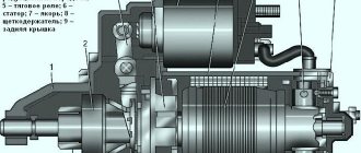
The starter device includes the following mechanisms:
- The cap, which is located on the drive side. It is equipped with an intermediate type ring.
- Rubber plug.
- Drive handle.
- Starter relay - located in the block of the mechanism itself.
- Manifold cover.
- Brush.
- Spring mechanism.
- Protective cover.
- Retaining type ring.
- Adjusting washer.
- Pinch bolt and anchor.
- Tube for insulation.
- Overrunning clutch with drive gear.
- Restrictive system.
The starter activation diagram is presented in the KamAZ user manual.
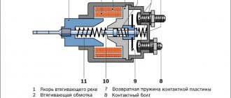
When the ignition switch is turned on, an automatic device supplies a control voltage flow to the retractor mechanism, which engages the Bendix gear in mesh with the flywheel.
At this time, the starter begins to rotate. When the ignition key is turned to any other position, the power to the solenoid relay is turned off. A return type spring relieves tension from the coil housing. The relay disengages the bendix from the flywheel housing and turns off the power.
Specifications
Starter technical parameters:
| Rated voltage, V | 26 |
| Mechanism power | 10.5 l. With. |
| Voltage required to turn on the traction mechanism relay, V | Pull-in winding - 8 Holding winding - 5 |
| Minimum brush height, cm | 1,3 |
| Brush spring pressure, kgf | From 1.75 to 2.06 |
| Maximum number of armature revolutions | 6400 |
| Maximum no-load current, A | 150 |
| Battery capacity | 190 Ah |
| Direction of rotation of mechanisms | Right |
| Drive gear | Eat |
| Number of teeth | 10 |
| Gear module, mm | 3,75 |
| The angle at which the teeth are located | 20° |
| Weight, kg | 24.7 thousand |
| Brushes tension force, N | From 10 to 14 |
| Voltage during idling, V | 12 |
| Wire cross-section, mm | 2,26*3,53 |
| Number of poles | 4 |
| Number of turns on coils | 8 |
| Shaft speed | At least 4 thousand revolutions per minute |
Starter malfunctions and repairs
KamAZ starter malfunctions and do-it-yourself methods for eliminating them:
- The mechanism does not start. This may be due to a short circuit or break in the pull-in winding of the traction relay, a contact in the power circuit. It is recommended to replace the relay, find the location of the damage and restore the broken contact, wipe the commutator, replace the brushes and springs.
- The traction mechanism relay does not operate. The cause of the breakdown may be a break in the pull-in winding, a malfunction of the instrument switch and the starter. In this case, you should rewind the winding, replace worn parts and the switch.
- During operation of the power unit starting system, extraneous noise and gear knocking are heard. In this case, it is recommended to adjust the gaps between the gear and the thrust washer and eliminate the fault at the contact connection point.
Why it doesn’t turn and what to do
Reasons why the starter does not work (clicks but does not turn):
- discharged battery;
- unclear contact in the starter circuit;
- damaged solenoid relay;
- short circuit in the winding;
- mismatch between the viscosity of the engine oil and the temperature conditions;
- malfunction of the ignition switch contact group;
- slipping of the freewheel;
- tight movement of the shaft along the thread.
The repair includes the following work:
- Charging the battery.
- Checking the mass of the main and solenoid relays.
- Inspection of the power circuit.
- Tightening the mounting bolts on the pads.
- Checking the voltage on the control wire.
- Inspect the mechanism for a short circuit in the system.
- Diagnostics of the ignition switch contact group and troubleshooting.
- Change of oil.
- Cleaning threads from debris.
- Lubricate threads with oil.
How to remove and disassemble
To remove the starter you need to:
- Remove the terminals from the battery.
- Remove the battery.
- Remove the air filter housing.
- Unscrew the bracket.
- Disconnect all wires.
- Unscrew the lower mounting bolt.
- Pull out the bendix and starter.
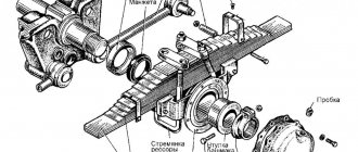
Disassembling the Magneton launch system:
- Unscrew the bolts located on the cover and on the main part of the starting system itself.
- Remove the partitions between the output type bolt and the mechanism winding.
- Unscrew the fastening nuts.
- Bend back the washers located on the system lock.
- Remove the screws from the cover, which is located on the side of the collector device.
- Remove the screws from the winding and brushes.
- Remove the brush.
- Unscrew the bolt from the adjusting flange.
- Remove the lever shaft.
- Unscrew the screw located on the side of the drive cover and remove the relay housing.
- Bend back the lock washer.
- Remove the cap and drive lever.
- Remove the thrust washer.
How to connect
Installing a starter on KamAZ A41 and connecting the engine starting mechanism relay:
- Place the car on a special platform.
- Wear safety glasses.
- Disconnect the positive terminal from the battery.
- Block the movement of the rear wheels.
- Unscrew the mounting bolts.
- Install the starter and connect the wires to it.
- Screw the mounting bolts into place.
- Connect the positive terminal of the battery to the starter terminal.
- Connect the red wire, which is located near the right headlight of the vehicle, to a cable with a connector.
- Set the vehicle to idle.
- Turn the ignition key.
- Connect the cable to the positive terminal of the battery.
- Once the engine starts, the cable connected to it must be removed.
- Reinstall the old battery connector.
- Remove the vehicle from the support stand.
What is the price
The average cost of a starter for KamAZ is 9.5 thousand rubles.
specmahina.ru
Varieties
There are several types of these mechanisms:
The KamAZ starter belongs to the first type of device. This mechanism is the most powerful, since here the transmission of torque from the armature to the gear is carried out by a gearbox. Such starters have not only high power, but also good starting torque. They also have a long service life. These types of starters are used on 90 percent of modern cars.
As for gearless elements, they operate as follows. After voltage is applied to the electromagnetic switch, the Bendix gear moves and engages the flywheel ring. Current flows to the armature. Rotation occurs. The gear and shaft are aligned using a freewheel. After the engine has started successfully, this connection is released. The current supply stops and the gear returns to its original position. Due to low efficiency and low maintainability, gearless elements are practically not used in the automotive industry.
How to remove the starter from a KAMAZ video
How to remove the starter on a Kamaz car (Theory)
KAMAZ starter
Repair of ST 142 KAMAZ starter
Ural 4320. Repair part 27, inspection of the KAMAZ 740 starter
starter repair. basic repair rules.
Starter solenoid relay repair disassembly
The starter of the YaMZ-238 Ural timber carrier “flew” Removal Repair Installation
How to check the starter yourself. Using a battery and two wires)
How to close the starter directly! What to do if the starter does not turn!
How to check the starter. Useful advice from an auto electrician.
Also see:
- Reviews from workers about KAMAZ
- KAMAZ cargo cover
- Single tires for KAMAZ
- KAMAZ 6x4 vehicle base
- A car similar to KAMAZ
- KAMAZ heater casing assembly
- KAMAZ 65115 body parameters
- Auto market KAMAZ 5511
- KAMAZ 43106 video
- Euro cab KAMAZ video
- Adjusting the KAMAZ oil pump video
- KAMAZ 5460 disadvantages
- KAMAZ four-circuit crane
- Filter rdv KAMAZ
- Model KAMAZ 53212 awning
Home » Hits » How to remove the starter from a KAMAZ video
kamaz-parts.ru
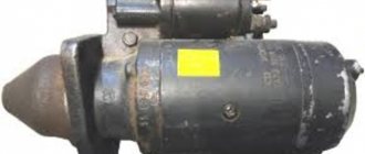
Device
Structurally, the KamAZ starter is an electric motor with a traction relay and a mechanical drive. This mechanism is installed on the flywheel housing (located on the left side of the engine). It is secured with three bolts and studs.
The mechanism is based on a 4-pole electric motor with sequential excitation. The starter design also includes the following elements:
- Drive shaft.
- Anchor.
- Back and front cover.
- Collector.
- Brush unit.
- KamAZ starter retractor relay.
- Excitation winding.
All this is combined into a metal case. Externally, the KamAZ starter looks as shown in the photo below.
The body is made of low carbon steel. It serves as a magnetic circuit where the cores are attached. The housing is closed with lids. The back one hides the brush assembly. Front - drive mechanism. The exciting winding is divided into parallel branches, which use series-connected coils. Copper wire with a rectangular cross-section is used as the winding. One end of it is connected to the positive brushes, and the other to the insulated terminal of the housing.
All coils are impregnated with a special varnish and additionally braided with cotton tape. The turns are insulated with cable paper.
ElectroSanya › Blog › Starter via relay and its blocking
I installed two relays for the starter, one powers the starter from the battery, to put it bluntly. There is no big difference in this, but the contacts on the ignition switch will no longer burn, if anyone has this problem! And I set the second relay to inhibit the starter when the engine is running, a very good thing, especially for training girls in the car, who, instead of turning off the car, turn on the starter. The principle of operation of the circuit is simple: when we turn on the starter, the circuit is closed, the starter turns, the engine starts, the generator supplies a minus signal to the “charge control lamp relay”, as well as to the starter blocking relay
Comments 20
Something's not working
What and what kind of generator? Perhaps it’s not a minus coming from the generator, but a plus! Another option, as I did now, is to connect the battery to the charge lamp
When the generator is excited, it goes +
then pin 86 of the second relay is not to +12 but to ground
In the diagram, 30 and 87 are closed.
yes it is on the diagram
good topic, I want to install 1 relay for myself)))
one thing is good, but there were cases when the engine cannot be heard at idle or a girl is driving and accidentally continues to hold the starter after starting, so the blocking is a cool thing
Probably not, but where should it hang?
What amperage should the relay have? or which specific ones need to be found by marking?
for the starter relay, preferably 30A; for blocking, the 702 charging relay is best, it is suitable
Thanks for the blog. Healthy.
What amperage should the relay have? or which specific ones need to be found by marking?
Gray, why don’t you have a relay for the starter))
Great. I've been wanting to do this for a long time. Now draw a diagram to use only one relay - Starter blocking.
Well, you take the lower relay closed and that’s it! relay 702 from charging is suitable, or 5-pin but instead of 87 use 88
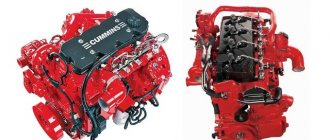
Cummins ISLe
Cummins ISLe series engines are six-cylinder in-line diesel engines with a displacement of 8.9 liters and power ranging from 276 to 375 hp. Developed from the C8.3, Cummins ISLe engines feature:
- Common Rail fuel system (provides high fuel injection pressure, maintains optimal performance at low engine speeds, reduces engine noise by up to 30%)
- new electronic control unit for multi-stage injection Cummins
- optional Jacobs compression brake (develops braking power 220 hp or 330 hp)
- modernized cylinder block (removable cylinder liners with mid-fixation simplify repairs)
- composite pistons
- Valve drive: cam shaft, roller cam followers, which contributes to high durability.
- Latest Fleetguard filters and improved lubrication system
All of the above influenced an increase in the power range with increased strength and a larger displacement, an increase in the oil change period and overhaul mileage to 850,000 km.
The ISLe series combines the advantages of a lightweight and compact motor with the structural robustness of heavy motors. Cars with ISLe engines can easily cope with work in harsh climatic conditions: be it the far north or the tropics/subtropics, as well as in off-road conditions. The ISLe engine model is designed for installation in single trucks and medium-sized tractors. With a weight of just over 700 kg, the engine shows excellent results on trucks operating in Russian conditions, ensuring the transportation of large volumes of materials. ISLe engines are distinguished by the following technical characteristics: high service life (1,000,000 km), increased power, maximum torque level, environmental friendliness (Euro3 and Euro4 requirements) and the lowest weight in the Cummins class.
Standard electrical sensor
On engines, KamAZ 740.31.240, vehicles KamAZ-43118, 43114, etc., the MM370 product is used as a standard lubricant pressure measuring device. This control mechanism is produced in the city of Vladimir. Visually, the device is a cylinder with a threaded connection at the bottom. The thread connects the part to the working area of the lubrication system. The top part is used to connect wires.
Lubricant pressure meter for KamAZ MM-370 vehicle:
Technical characteristics of the electrical device MM-370
| Index | Meaning |
| Length, mm. | 70 |
| Cylinder, section, mm. | 40 |
| Threaded connection | M14 by 1.5 |
| Hexagon, mm | 19 |
| Pressure range, kgf/cm 2 | 0-10 |
| Resistance, Ohm | 159-173 |
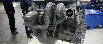
Increased vibrations in a Cummins diesel engine
The most common causes of increased vibrations:
- damage to engine mounts,
- failure of the vibration damper,
- unstable operation of the cylinders.
If these reasons are excluded, the task of finding the source of vibration becomes much more complicated. The Cummins 6isbe285 repair manual will help you determine the reasons.
Vibrations can be caused by mounted units of different weights and rotation speeds. The wear and tear of the internal components of these units may affect them. Therefore, very often, special equipment is used in service centers to determine the source of vibrations.
Change in color or density of exhaust smoke from Cummins ISBe engines
Exhaust gases can be used to determine the condition of the engine and the cause of the malfunction.
The ambient temperature should not fall below 210C, and the engine should be warmed up. Otherwise, the ignition period of the fuel increases and only part of the mixture burns (this is indicated by gray or white smoke).
Depending on their consistency, exhaust gases are divided into three groups:
- soot or cold smoke (color from gray to white),
- hot or dense smoke (density from 20% to 100%),
- light blue smoke.
Soot or cold smoke is a consequence of incomplete combustion of fuel (a small part is burned). The cause may be insufficient compression due to broken piston rings, piston ring pads, leaking valves or improper adjustment.
Owners of Valdaevs powered by Kamens engines in their reviews come to the conclusion that this car is the most suitable for Russian off-road use.
Poor quality fuel can lead to wear and erosion of injectors. In addition, like other car parts that interact with hydraulic fluids and air, injectors are susceptible to corrosion. Read about injector malfunctions and repairs here.
In this case, you need to check the valve adjustment, compression in the cylinder and the presence of signs of gas breakthrough into the crankcase. The cause of soot may be a leaking injector, improperly adjusted injectors, an enlarged mouthpiece hole, or too much coolant entering the combustion chamber.
Hot or dense smoke is a consequence of incomplete combustion of fuel (most of the fuel burns). The reason is insufficient filling of the cylinders with air or excessive fuel supply. Light blue smoke is an indicator of excessive oil entering the combustion chamber.
For a more detailed inspection of the engine or its disassembly, it is recommended to contact a specialized service center or use the Cummins ISBe repair manual.
Atmospheric pressure sensor
The sensor is attached to the wiring harness without attaching it to the engine using bolts, on the left side.
If the sensor fails, the controller runs a bypass program using the calculated average atmospheric pressure.
Disconnect the negative terminal of the battery
We cut the clamp securing the atmospheric pressure sensor to the engine wiring harness
Move the locking bar of the wiring harness block
Disconnect the atmospheric pressure sensor from the block
The sensor can only be checked with a diagnostic tester.
We install the atmospheric pressure sensor and attach it to the engine wiring harness with a new clamp.
Replacing the control device
Dismantling and installing new equipment is not difficult thanks to the convenient location of the sensor. When carrying out manipulations, perform the following actions:
- Turn off the ignition of the power plant, open the hood of the car;
- Remove the hose from the sensor and remove the product from the holder;
- Treat the mounting socket with a sealed solution, install a new device;
- Connect the hose to the sensor, having previously coated it with a sealed solution;
- Connect the hose to the pressure gauge.
Daily monitoring of oil level, fluid pressure, fuel quality is an indispensable condition for the normal operation of the KamAZ power plant. The procedures performed are not difficult, so they are carried out by drivers of any qualification. At the same time, neglecting these simple manipulations will lead to serious and irreparable consequences, which are easier to prevent than to eliminate.
The Cummins 6ISBe is an easy to operate and manage six-cylinder engine that is considered the quietest engine in the series.
Combined boost pressure/intake manifold air temperature sensor
The air pressure and temperature sensors in the intake manifold are combined into a single unit.
The sensor is installed on top of the engine intake pipe.
If the combination sensor is faulty, the controller limits the boost pressure and engine power is reduced.
Disconnect the negative terminal of the battery
Squeeze the wire block clamp
Disconnect the wire block from the sensor
Unscrew the screw securing the combined sensor.
Remove the sensor from the engine by pulling it vertically upward.
When removing the sensor, be careful not to damage the O-ring and plastic guard surrounding the sensor tip. Do not use the lever to avoid damaging the plastic guard.