Purpose of the ISRK-12 “Host” feed dispenser
Mobile feed grinders-mixers-dispensers ensure the preparation and standardized distribution of multi-component feed mixtures for cattle.
The advantage of mobile feed grinders-mixers-dispensers is the high efficiency of their use compared to mobile feed dispensers that do not provide grinding and mixing of components.
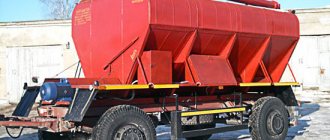
The feed chopper-mixer-dispenser ISRK-12 “Host” is a universal transport and technological means for preparing (re-grinding and mixing) components (green mass, powered stalked feed, scattered and pressed hay, straw, compound feed, crushed root vegetables, liquid feed additives). The use of an electronic feed mixture weighing system makes it possible to program 50 recipes from 30 components.
It is used on dairy farms and has the ability to distribute feed mixtures to both one and both sides at the same time.
Siloking feed dispensers
The German company specializes in the production of agricultural machinery for servicing livestock. In particular, the company produces a number of models of trailed and self-propelled feed mixers. The company is a manufacturing holding with enterprises and sales offices located in Europe, Canada, Brazil, China and Russia.
Trailed mixers and feed dispensers Siloking
Versions of trailed distributors are presented in two and single auger models, where mixing and grinding is carried out by vertically located working bodies. Setting up mixing processes is carried out from the tablet via wireless communication with the on-board computer of the dispenser. The shape of the bunker and the dynamics of the augers ensure ideal mixing of the feed mass. The mixing auger, hopper walls and bottom are covered with wear-resistant material.
Trailed distributor Siloking
Self-propelled feed dispensers - Siloking mixers
The machines are distinguished by high maneuverability due to the three-point chassis design. In narrow farm passages, the dispenser is capable of dispensing feed mixture on both sides without the wheels running into the lump table. The supporting hollow frame of the machine ensures rigidity of the structure and accuracy of weighing components during the preparation of mixtures. The loading cutter with a working width of 2 meters is equipped with 42 curved teeth and ensures efficient loading of the hopper through a channel with a width of 700 mm. Depending on the model, self-propelled feed dispensers are equipped with four and six cylinder VoLvo engines.
In addition, the company presents a model of a feed dispenser with a vertical turbo auger on an electric drive without an independent loading function and a self-propelled electric haylage dispenser with a loading function.
Self-propelled electric feeder Siloking
Electric silage distributor Siloking
The device of the ISRK-12 “Host” feed dispenser
The ISRK-12 feed dispenser (Fig. 1) consists of a traction device 10, a hopper 1, a screw working element, a weighing mechanism, an unloading scraper conveyor, a drive of working elements, a brake system, a hydraulic system, a brake axle with wheels, a control panel for working elements 13, a display weighing mechanism 14.
Rice. 1. General view of the ISRK-12 feed dispenser: 1 – bunker; 2 – support wheel; 3 – unloading scraper conveyor; 4 – dosing valve; 5 – measuring ruler; 6 – parking brake steering wheel; 7 – battery box; 8 – support post; 9 – gearbox; 10 – traction device; 11 – stairs; 12 – observation deck; 13 – remote control; 14 – display of the weighing mechanism; 15 – pressure gauge; 16 – oil tank
Hopper 1 has a rectangular shape in the horizontal plane, and a prismatic shape in the vertical transverse plane with an upward expansion.
On the front wall of the bunker there is a display 14 of the weight mechanism for controlling the working bodies, as well as an observation platform 12 and a ladder 11 for climbing to the platform.
To the left and/or right along the distributor, in the middle part of the bunker 1, an unloading scraper conveyor 3 is installed. The scraper conveyor is driven by a hydraulic motor 1 (Fig. 2). The angle of inclination of conveyor 2 (height of distribution into feeders) is adjusted by hydraulic cylinder 3.
The speed of movement of the conveyor 2 is changed by hydraulic motor 1, controlled from the tractor cabin. Changing the speed of movement of the conveyor 2 allows you to select the rate of distribution of feed to animals, which is done experimentally.
In the transport position (Fig. 2, b), the unloading scraper conveyor 2 is fixed vertically.
Rice. 2. Unloading scraper conveyor: a – working position; b – transport position; 1 – hydraulic motor; 2 – scraper conveyor; 3 – hydraulic cylinder; 4 – dosing valve; 5 – bunker; 6 – auger; 7 – support wheel
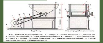
The unloading scraper conveyor (Fig. 3) consists of a housing 1, between the side horizontal walls of which the drive 6 and driven 7 shafts are fixed in housings with bearings 11.
Rice. 3. Diagram of the unloading conveyor structure: 1 – conveyor body; 2 – bar; 3 – flange; 4 – gasket; 5 – bottom; 6 – drive shaft; 7 – driven shaft; 8 – asterisk; 9 – coupling; 10 – bolt; 11 – bearing housing; 12 – conveyor chain
On shafts 6 and 7, sprockets 8 are installed, on which a conveyor chain 12 is mounted, the slats 2 of which, in operating mode, move to the bottom 5. To protect the conveyor chain 12 from breakage under excessive load, a safety clutch 9 is installed on the driven shaft 7.
The tension of the conveyor 12 chains is carried out by moving the driven shaft 7 using tension bolts with a torque of 200 N∙m. Over-tightening of the conveyor 12 chains causes accelerated wear of the chains and sprockets 8.
To the right along the feed dispenser, in the middle part of the bunker 1, there is also an unloading hatch 2, from which the feed mixture falls into the unloading tray 3 (Fig. 4). Raising and lowering tray 3 is done manually by changing the length of chain 4.
Rice. 4. Unloading hatch with a dosing device: 1 – hopper; 2 – unloading hatch; 3 – unloading tray; 4 – chain; 5 – slide valve; 6 – hydraulic cylinder; 7 – lever; 8 – traction
The rate of delivery of the feed mixture through the unloading hatch 1 or using the unloading conveyor is regulated by a slide valve 5, opened by a hydraulic cylinder 6 using a lever 7.
The opening value of the gate 5 is controlled visually by the position of the thrust lever 8, connected to the hydraulic cylinder rod, and by the marks marked on a special measuring ruler 5 (see Fig. 1), mounted on the front wall of the hopper 1.
In the lower prismatic part of the hopper 1, two mixing and grinding screws 2 are installed along its axis (Fig. 5).
To grind the mass along the entire length of the turns 3 of the augers 2, main knives 4 with a wavy blade edge are fixed. Additional cutting of feed shifted to the middle of the hopper 1 is carried out by pruning knives 6 attached to coils 3.
Rice. 5. Mixing and grinding device: 1 – hopper; 2 – screws; 3 – turn; 4 – main knife; 5 – counter plate; 6 – knife-cleaver; 7 – shoulder blade
The creation of a counter-cutting effect is ensured by a counter-cutting plate 5 located between the screws 2.
Each of the augers installed in the bunker for transporting and mixing feed components has an opposite winding of turns 3, ensuring the transportation of the mixed feed components. In the middle part of the screws 2 there are blades 7 that direct the mass flow upward.
On the rear wall of the hopper 1 there is a lattice window 2 for manual loading of various bulk additives and premixes (Fig. 6).
Rice. 6. Loading window: 1 – rear wall of the hopper; 2 – lattice window; 3 – brake shoe; 4 – lantern
A weighing device with a terminal allows you to prepare complete feed mixtures with a given energy value. The weighing mechanism consists of measuring weighing rods, an electronic display 1 with a control keyboard 2, visible from the tractor cabin, and switching connections (Fig. 7). The measuring system has a manual setting mode, an automatic weighing mode with readings displayed on display indicator 1, an audible alarm and a blocking of the weighing system when the unit moves to additional loading points.
Rice. 7. Remote control: 1 – display of the weighing mechanism; 2 – control keyboard; 3 – pressure gauge
The working elements, the conveyor drive, and the opening and closing of the side flaps are controlled from the hydraulic system of the feed dispenser from the tractor cabin using a remote control.
The drive of the working parts of the feed dispenser and the grinding and mixing augers is carried out from the main two-stage planetary gearbox 1, installed in the front part of the frame 2, and the chain transmission system 3 of the auger drive (Fig. 8). Power is transmitted to the main gearbox by a cardan shaft from the tractor PTO at a speed of 540 rpm.
The drive of the remaining working parts is carried out using an autonomous hydraulic system, controlled remotely from the tractor cabin, including a hydraulic pump, a hydraulic motor for driving the unloading conveyor, hydraulic cylinders for driving the gates and tilting the conveyor, a hydraulic tank, hydraulic valves, control devices and safety valves.
Rice. 8. Drive of working parts: 1 – two-stage planetary gearbox; 2 – frames; 3 – chain drive; 4 – stairs
The pneumatic drive of the feed dispenser brakes is connected to the pneumatic drive of the tractor and is controlled together with the tractor brakes. The parking brake is controlled using a screw drive mounted on the feed dispenser frame.
The braking system consists of a pneumatic service brake interlocked with the tractor brakes and a mechanical parking brake.
The service brake is driven from the pneumatic system of tractor 1 and is controlled together with the tractor brakes (Fig. 9).
Rice. 9. Chassis system and brakes: 1 – receiver of the tractor pneumatic system; 2 – pneumatic chamber; 3 – brake drum; 4 – bridge beam; 5 – wheels; 6 – bunker
The parking brake drive is mechanical and manual. It is produced using a screw mechanism mounted on the frame of the feed dispenser. Drum brakes.
The running system is a bridge with wheels. The bridge beam 4 with wheels 5 is connected to the hopper. There is a light alarm on the rear wall of the bunker, connected to the tractor controls.
Traction device 10 is a welded structure, rigidly fixed to hopper 1 and used for coupling with the tractor's traction device using an earring. It is equipped with a height-adjustable support post 8 (see Fig. 1).
The units have different volumes and performance levels. The feed dispenser is aggregated with tractors of class 1.4. The machine is serviced by one tractor driver.