GAZ-3309 is a medium-tonnage vehicle that is excellent for transporting goods over short and long distances. All thanks to its impressive technical and operational characteristics and load capacity. This vehicle is equipped with a diesel power plant. The first models of the machine were available in the 1990s.
Scope of application of GAZ-3309
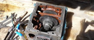
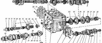
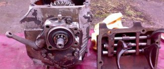
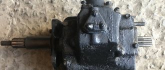
Appearance of the GAZ 3309 gearbox
The main area of application of the GAZ-3309 is agriculture and construction. The machine can mark an open body where you can fill crushed stone, grain, transport industrial equipment, construction waste, etc. Motor transport is distinguished by a reliable chassis, thanks to which transportation occurs quickly. The transmission system mechanisms are designed for heavy loads. Many private owners were able to appreciate the reliability and practicality of these trucks.
Design and operation of the gear selection (switching) mechanism
The basis of this gearbox assembly is made up of three horizontal rods that can move axially forward and backward. A fork is rigidly installed on each rod (using pinned bolts), which covers the synchronizer clutch or gear-carriage, ensuring its movement. Also on the rods (in a 4-speed gearbox - approximately in their middle part, in a 5-speed gearbox - in the front part) shift heads with grooves for the lever head are rigidly installed.
Each rod has a lock (located in the front part), which ensures that the gear is retained. The retainer consists of a ball, which, under the action of a spring, rests against a recess on the rod, preventing its axial displacement without applying force to the lever. In total, each rod has three grooves, so it can occupy three positions - forward, neutral (middle) and rear. In 4-speed box, the reverse gear shift rod has two recesses. The clamps are located above the rods in special wells in the gearbox cover.
Transmission system features
The GAZ-3309 high-speed gearbox has a long service life. The car is equipped with a 5-speed manual transmission as standard. At the same time, all gears except first and reverse have inertial synchronizers. Changing speed modes is carried out using a lever. The weight of this unit is more than 70 kg. Considering this, if its removal is required, you should be as careful as possible. The present power take-off box on the GAZ-3309 can have a mechanical or pneumatic activation.
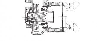
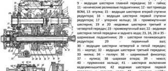
GAZ 3309 gearbox diagram
Transmission gears have helical teeth, with the exception of reverse gears. The main mechanisms of the crankcase are the primary and secondary shafts on ball bearings. This is well illustrated by the diagram of this working mechanism. The switching forks are fixed with bolts and washers.
The gearbox on the GAZ-3309 allows you to change the speed. There is a locking device in the rear housing. There is also a fitting here. To prevent dirt and water from getting into the gearbox, the manufacturer installed a special seal.
Thus, the operation of the GAZ-3309 helps to increase the productivity of construction and agricultural work. Comfortable handling has determined the demand for a car of this class. Thanks to the elevated ground clearance, the vehicle has good maneuverability. The gearbox present on the truck allows you to change speed modes without loss of operating power.
Removing and installing box 3307
Dismantling and installing the gearbox is easy. You only need to take into account the weight of the unit (56 kg), so removal and installation requires 2 or 3 people. The easiest way to do the work is in a pit. We perform dismantling in the following order:
- We disassemble the floor in the cabin near the gearshift lever;
- Remove the gear lever;
- Unscrew the cardan shaft;
- Disconnect the handbrake rod from the box;
- Remove the clutch fork;
- Unscrew the speedometer cable;
- We unscrew the four nuts securing the box to the engine flywheel housing;
- We dismantle the box.
Install the gearbox in the reverse order. If the unit is subject to repair, it is more convenient to drain the oil immediately while the gearbox is still on the car.
Transmission faults
As a rule, repair of the GAZ-3309 gearbox is necessary as a result of wear of its component parts. It should be noted the main signs of when there is a breakdown of the speed box:
- difficulty changing gears;
- spontaneous activation of speeds;
- there is a transmission oil leak;
- jerking, extraneous noise when changing speeds.
If the listed problems are present, it is advisable to conduct a general diagnosis of the transmission system. In some cases, replacing the oil and worn components can solve the problem of gearbox operation. Fuel leaks are often due to the fact that the seals have lost their properties. Excessive noise may be the result of broken teeth. New spare parts for the gearbox on the GAZ-3309 should be selected based on the characteristics of the truck’s operating system.
If you need to replace the fuel in a manual transmission, it is recommended to opt for TAP-15v. As a rule, the need to carry out this procedure for GAZ-3309 owners arises after 40,000 km.
The existing drain plug has a magnet to attract wear debris that may be present in the oil.
Important! When replacing fuel, the magnet must be cleaned. An increased content of metal shavings on this element is evidence that the liquid has lost its working properties. The oil must be changed.
Controls and instruments
The location of the controls for the GAZ-3307 and GAZ-3309 vehicles is shown in Fig. 5.1.
Rice. 5.1. Controls
1, 8
—
nozzles for blowing the cabin glass.
2 — instrument panel.
3 — lever for switching direction indicators, headlights and sound signal*.
The lever has six fixed positions - I, II, III, IV, V and VI and four non-fixed positions “A” (Fig. 5.2 and 5.3).
If the switch lever is in
position I and the central light switch is in position II, then the low beam headlights are on. By moving the lever to position II, the high beam headlights come on and the blue indicator light comes on. When the switch lever is repeatedly moved from position I towards you along the steering column (non-locking position), the high beam headlights are signaled. When you press the lever button (from any position) along the axis, a sound signal is activated (without locking) - see fig. 5.2.
* On some vehicles, the sound signal is turned on by the windshield wiper and washer switch (see Fig. 5.5).
Rice. 5.2. Lever position
turn signal switch and headlight
switch (with sound
signal)
Fig. 5.3. Turn signal and headlight switch positions (without horn)
When the lever is moved from position I or II up to position VI or IV (right turn) or down to position V or III (left turn), the direction indicators turn on and a green flashing warning light comes on in the instrument cluster. The switch has an automatic device for returning the lever to position I or II after the end of the turn. To briefly turn on the direction indicators, the switch lever must be moved to the corresponding non-fixed position “A”. When released, the lever returns to position I or P.
4 — steering wheel.
5 — wiper, washer and horn switch lever*.
When the lever is in position (Fig. 5.4): 0 - the windshield wiper is off; I — low speed windshield wiper is on; II - high speed windshield wiper is turned on, III - intermittent wiper operation is turned on.
When the lever is in position (Fig. 5.5): 0 - the windshield wiper is off, I - intermittent operation of the windshield wiper is on; II — low speed windshield wiper is on; III - high speed windshield wiper is on.
* On some cars, the sound signal is turned on by the turn signal and headlight switch (see Fig. 5.2).
If the switch does not have a horn switch (Fig. 5.4), then moving the lever towards you (in the direction of the arrow) from position 0 briefly turns on the washer and wiper.
Rice. 5.4. Windshield wiper and washer switch positions (without horn)
Rice. 5.5. Windshield wiper and washer switch positions (with sound signal)*
If the switch is equipped with a sound signal switch (see Fig. 5.5), then to turn on the washer and wiper for a short time, the switch lever must be moved from position 0 away from you (in the direction of arrow “A”), and to turn on the sound signal, the lever must be moved (from any position) toward you (in the direction of arrow “B”).
The washer can be turned on from all positions of the lever. The windshield wiper only works when the ignition is on.
6 — removable fuse box panel.
On the inside of the panel there are signs indicating the consumers protected by these fuses.
7 — glove box.
9 — control knob for electric headlight adjustment
depending on the vehicle load (Fig. 5.6).
When the corrector knob is in position:
0 – corresponds to an unloaded vehicle;
1 – corresponds to a fully loaded car
Rice. 5.6. Handle of the headlight range control unit
* On some cars, the sound signal is turned on by the turn signal and headlight switch (see Fig. 5.2).
10 — air control knob and heater.
When the handle is in the upper position, only outside air enters the heater; when in the lower position, air from the cabin enters. At any intermediate position of the damper, a mixture of outside air and air from the cabin enters the heater.
11 — heater valve control handle.
Turns on the supply of fluid from the engine cooling system to the cabin heater radiators.
12 — battery switch (installed on some cars).
13 — gear lever. The gear shift diagram is shown in Fig. 5.7.
Rice. 5.7. Gear shift pattern
14 — midnight brake lever.
15 — push-button switch for glow plugs
(for GAZ 3309 with D-245.7 E3 engine).
16 — ignition, starter and anti-theft switch
(for GLZ-3307);
electrical equipment, starter and anti-theft device
(for GAZ-3309).
The switch key has four positions (Fig. 5.8):
0 - everything is turned off;
I — ignition is on (GAZ-3307), instrumentation is on (GAZ-3309);
II - the ignition and starter are turned on (GAZ-3307), instrumentation and starter are turned on (GAZ-3309);
III - the ignition is turned off and, with the key removed, the anti-theft device is turned on (GAZ-3307); the instrumentation is turned off and, with the key removed, the anti-theft device (GAZ-3309) is turned on.
To turn off the anti-theft device, insert the key and, slightly rocking the steering wheel left and right, turn the key to position 0. To avoid failure of the contact part of the instrument switch and starter, do not leave the key in an intermediate position.
Rice. 5.8. Key positions of the ignition switch (instruments), starter and anti-theft device
17 — throttle pedal (GAZ-3307) or fuel control pedal (GAZ-3309).
18 — brake pedal.
19 — clutch pedal.
20 — manual control handle for the fuel supply drive.
21 - alarm switch (Fig. 5.9).
When the position is on, all the direction indicator lamps and the red indicator inside the hazard warning light switch off button light up simultaneously in a flashing mode.
22 — blinds pull handle.
23 — hood lock handle.
24 - plug socket.
Rice. 5.9. Hazard warning switch button
The location of the instruments of the GAZ-3307 car is shown in Fig. 5.10.
Rice. 5.10. Instrument panel of the GAZ-3307 car
1 — indicator (red) for emergency drop in oil pressure and clogged oil filter.
Lights up at an oil pressure of 40–80 kPa (0.4–0.8 kgf/cm2).
2 — button for checking the serviceability of the indicator lamp unit.
When you press the button, the indicator lamps
6, 7 and 8
if they are in working order.
3 — indicator (green) for turning on the trailer direction indicators
(intermittent signal).
4 — indicator (green) for turning on the vehicle's direction indicators
(intermittent signal).
5 — indicator (green) for turning on the side lights.
6,7 — backup alarms.
8 — indicator (red) for an emergency drop in the brake fluid level and activation of the parking brake.
When the ignition is on, it lights up when the brake fluid level in the master cylinder reservoir is below the “MIN” mark or when the brake is in the midnight position.
9 - indicator
(red) of engine coolant overheating.
Lights up when the coolant temperature is above 105***C.
10 — indicator (blue) for turning on the high beam headlights.
11 — speedometer with total vehicle mileage counter.
12 — pressure gauge for monitoring air pressure in the front brake circuit.
13 — engine management system diagnostic indicator.
14 — rear fog light switch.
15 — heater fan low speed switch.
When the switch is in the on position, the light bulb (green filter) lights up.
16 — heater fan maximum speed switch.
When the switch is in the on position, the light bulb (green filter) lights up.
Electric motors operate at maximum rotation speed when switches 13 m 15
. When only one switch
15
, the electric motors do not work.
17 — central light switch
(Fig. 5.11).
The switch has three fixed positions:
0 - everything is turned off;
I — side light and license plate light are on;
II - side light, license plate light, low beam or high beam are on. By turning the central light switch knob clockwise, the intensity of the instrument lighting is adjusted.
Rice. 5.11. Positions of the central light switch
18 — ABS diagnostic switch.
19 — ABS fault indicator.
20 — pressure gauge for monitoring air pressure in the rear brake circuit.
21 — current indicator.
22 — coolant temperature gauge.
23 — fuel level indicator.
24 — indicator (orange) of the minimum fuel reserve in the tank. Constantly lights up when the remaining fuel in the tank is less than 12 liters.
25 — engine oil pressure gauge.
The location of the instruments of the GAZ-3309 car is shown in Fig. 5.12.
Rice. 5.12. Instrument panel of the GAZ-3309 car
1 — buttons for checking the serviceability of the lamps of the left and right blocks of control lamps.
When you press buttons
1
, the lamps of the right or left blocks light up if they are in working order, except for the lamp pos. 9, which is checked when the power to the devices is turned on (position I of the instrument key, starter and anti-theft device).
2 and 11
-
backup alarms.
3 - indicator (green) for turning on the trailer direction indicators
(intermittent signal).
4 — indicator (red) of coolant overheating.
Lights up when the coolant temperature is above 105° C.
5 — signaling device (green) for turning on the side lights.
Lights up when the side lights are turned on.
6 - indicator (green) for turning on the vehicle’s direction indicators
(intermittent signal).
7 — diagnostic indicator of the engine management system.
8 — signaling device (blue) for turning on the high beam.
9 — indicator (orange) of glow plugs.
10 — indicator (orange) of generator malfunction.
Lights up when the generator is faulty.
12 — indicator (red) of air filter clogging.
Lights up when the vacuum in the inlet pipe of the intake pipe reaches 6.35 kPa (650 mm head).
13 - ABC fault indicator.
14 — rear fog lamp switch.
15 — signaling device (red) for turning on the parking brake.
16 — low speed heater fan switch.
17 - indicator (red) of an emergency drop in the fluid level in the brake system reservoir
(intermittent signal). When the instruments are turned on, it lights up when the brake fluid level in the master cylinder reservoir is below the MIN mark.
18 — switch for maximum speed of heater fans.
Electric motors operate at maximum rotation speed when switches
16
and
18
.
When only one switch 18
, the electric motors do not work.
19 — switch for controlling glow plugs.
20 - ABS diagnostic switch.
21 — engine diagnostic request switch.
22 - central light switch
(see Fig. 5.11).
23 - pressure gauge for monitoring air pressure in the front brake circuit.
24 - pressure gauge for monitoring air pressure in the rear brake circuit.
25 - current indicator.
26 — fuel level indicator.
27 — indicator (red) of the minimum fuel reserve in the tank.
Constantly lights up when the remaining fuel in the tank is less than 12 liters.
28 — speedometer with a total distance meter.
29 - engine oil pressure indicator.
30 - indicator (red) of an emergency drop in oil pressure and clogged oil filter.
Lights up at an oil pressure of 40–80 kPa (0.4–0.8 kgf/cm2).
31 — coolant temperature indicator.
32 - tachometer.
Dismantling the GAZ-3309 gearbox
Before starting repair and restoration work on the gearbox, it is necessary to drain the fluid from it.
- If disassembly of the gearbox is required, it is advisable to unscrew the nuts and remove the power take-off hatch cover along with the gasket. The box must be placed in a vertical position on a special stand. Next, turn away: the flange, breather and other existing components. The fitting must be removed.
- The bolts that secure the boats, the GAZ-3309 secondary shaft bearing, and the input shaft covers are unscrewed. Next, you can begin to separate the crankcases, after which you need to remove the gasket from them.
- It is necessary to remove the intermediate shaft bearing ring and plugs, then you can begin to remove the input shaft. The bearing and washer must be dismantled.
- The next step is to unscrew the bolts that secure the gear shift fork. Then you should remove the secondary shaft. All adjacent parts must be removed. Plugs, springs, fuses, cuffs, studs, etc. are removed.
When a GAZ-3309 gearbox is repaired, it is necessary to check the condition of the shaft teeth and clean the components from deposits. Deformed, worn-out elements must always be replaced.
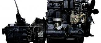
PAZ-32053-07 with a Minsk diesel engine
Everything that has been said about the design and layout of a bus with a gasoline engine is fully true for a car with a diesel engine. The main difference is the Minsk-made MMZ D-245.7 engine. It’s hard not to notice him when standing next to a bus with its engine running. You can immediately say: “He! Tractor "Belarus". PAZ specialists worked for a long time to reduce the noise of not only the engine, but also the entire bus as a whole, and as a result, its level was brought to the required certification standards, but the feeling of a tractor engine remained.
Inside the cabin, the engine is not very noisy, especially in comparison with the diesel PAZ six years ago. On that bus you had to talk with your voice very loud.
It cannot be said that a diesel car is significantly different from a gasoline car in terms of dynamic performance. But its fuel consumption is significantly lower, which has a very good effect on the profitability of the bus.
Technical characteristics of buses PAZ-32053, PAZ-32053-07, PAZ-4234
What’s most interesting is that the PAZ-32053-07 and PAZ-4234, which corresponds to the middle class and has a more powerful MMZ-245.9E2 diesel engine, have very similar fuel consumption figures. Please note that the motor is positioned as meeting Euro 2 environmental standards.
The extended bus is also equipped with a Zilov-made, but reinforced axle ZVL-433100 (RZAA) and a “Zilov” 5-speed manual gearbox made by the Smolensk plant, as on previous models.
Naturally, the “long” PAZ has slightly worse dynamics than its “short” counterparts, but the passenger capacity is 50 people, i.e. 10...11 people more than the small class PAZs. The car has rationally arranged passenger seats, and storage areas are organized opposite the two doors with pneumatic drive.