System design
The YaMZ 236 lubrication system is combined, oil is supplied by gravity, individual components are lubricated by splashing or forced, under pressure. The latter include parts experiencing maximum mechanical loads:
YaMZ-236 engine power supply system
- gear bearings of the oil pump drive, camshaft, connecting rod;
- pistons;
- bushings and some other components.
The remaining components of the engine compartment, including the inner walls of the cylinders and the camshaft cams, are treated with oil, which flows from the crankshaft bearings and is automatically sprayed when the connecting rods move.
The YaMZ engine lubrication system works in close contact with the fuel system.
Lubrication system
The lubrication system of YaMZ 236 engines, as already mentioned, is of a combined type, with a “wet” sump. Its main components:
YaMZ-236 engine lubrication diagram
- Carter.
- Oil intake.
- Oil pump.
- Pressure reducing valve.
- Radiator.
- First stage cleaning filter.
- Bypass valve.
- Signal LED or lamp.
- Centrifugal oil filter.
- Camshaft
- Pushers axis.
- Crankshaft.
- Differential valve.
- Piston cooling nozzle.
- Turbocharger.
- Throttle.
- Heat exchanger bypass valve.
- Fan switch.
- Fan drive.
- Injection pump.
The bypass valve in the radiator is included in the YaMZ lubrication system in order to divert part of the oil into the common line if the pressure difference before and after the heat exchanger is 274 KPa or exceeds this value. A similar device is located in the oil filter. It is triggered if the pressure difference at the inlet and outlet of the filter reaches 200–250 kPa. When the valve is activated, a light signal on the dashboard lights up, as this means a malfunction in the YaMZ engine lubrication system - either a clogged oil filter or thickening of the oil.
Diagram of the lubrication system of the YaMZ-236 engine
The most important element of the YaMZ lubrication system is the oil pump. It consists of a drive gear, a driven gear, an idler gear, a drive gear and a pressure reducing valve, and is driven by the crankshaft.
Pump design
The YaMZ oil pump supplies lubricant to the serviced mechanisms directly from the filter, and two sections of the pump pump oil to various engine components. The front part, with a pressure reducing valve, works for the general lubrication system, and the rear part pumps oil into the oil cooler.
Oil pump of YaMZ-236 engine
The pump receives oil from the oil pan. Its main, first section pumps lubricant into the coarse filter element. There, the oil flow is divided - part is sent to the fine cleaning unit, from where it is then drained back into the crankcase, and part - into the main line. In this way, the oil circulating in the YaMZ engine is permanently cleaned.
From the main line, oil is directed under pressure to the camshaft bearings and crankshaft main bearings. From these units it is led through the appropriate channels to the connecting rod bearings and pistons.
Under pressure, a stream of lubricant flows from the front camshaft support into the axis of the pushers to ensure the operation of the bushings. Subsequently, it spreads along the pusher rods and flows by gravity to the valve mechanism.
The rear section of the pump, working on the oil cooler, ensures timely cooling of the entire lubrication structure of the engine, since the cooled lubricant is supplied back to the crankcase.
YaMZ-236 engine lubrication system with a single-section oil pump and liquid-oil heat exchanger
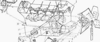
Cylinder block
The two cylinder blocks have a 90-degree angle between them and a common base, which is the upper part of the engine crankcase. To simplify the design, the connecting rods of opposite cylinders are mounted on one crankpin of the crankshaft. For layout reasons, the cylinder axes are offset by 35 mm. The cylinder block is made of gray cast iron with a low amount of alloying elements. When calculating the block, special attention was paid to ensuring rigidity, which made it possible to achieve high technical characteristics of the YaMZ 236 engine.
The cylinder blocks have replaceable liners of the so-called wet type - the coolant washes the outer part of the liners. The block contains supports for the camshaft and crankshaft bearings. Processing of crankshaft bearing beds is carried out with the covers installed. Therefore, the covers are not interchangeable and must be installed in a strictly defined position.
In the front part of the block there is a housing for the gear block of the gas distribution mechanism drive; in the rear part there is a flywheel housing, manufactured as a separate part. A coolant pump is installed on the gear housing cover. Liquid from the pump is pumped into the cylinder blocks through a channel in the cover and gear housing. Inside the cover there are additional passages for coolant. The gear cover has a milled plane with hatch marks that are used in conjunction with the mark on the crankshaft pulley to set the fuel injection start point. The fender installation of marks is an indispensable condition for ensuring the technical characteristics of the YaMZ 236.
The radiator section of the pump supplies approximately 20% of the total amount of oil supplied by the pump to the radiator for cooling. This amount is sufficient to maintain the required oil temperature in the oil pan.
The main section 13 of the pump supplies oil to the rubbing parts of the engine. Oil from the pump through channels in the cylinder block
enters the oil pre-cleaning filter 18, which is included in the oil system in series, i.e. all the oil supplied to lubricate engine parts passes through it. After the filter, the main amount of oil flows through the channel into the central oil channel 7, and from there through the channels in the block to the bearings of the crankshaft 8 and camshaft 15.
The crankshaft journal connecting rods have internal cavities 19, closed with plugs, where the oil is subjected to additional centrifugal cleaning. The cavities of the connecting rod journals communicate with the transverse channels in the main bearings through inclined channels. To lubricate the rubbing surfaces of the upper head of the connecting rod and the piston bosses, there is a channel along the body of the connecting rod 6 through which oil from the lower head of the connecting rod under pressure flows to the upper head. Oil is supplied through the metering point and then through the connecting rod channel to the piston pin.
Oil reaches the rubbing areas through the gaps between the surfaces of the bushing and piston bosses, on the one hand, and the piston pin, on the other.
From the front journal of the camshaft 15, oil is directed in a pulsating flow to the axis 16 of the pushers. Through a channel drilled along the axis, oil is supplied to the pusher bushings, from where it flows through the pusher channels into their heels. From here, the oil is supplied through hollow rods 5 to the rocker arms 4 and then through the holes in their body to the rocker arm bushings. Oil flows from the bushings into recess 2 of the cylinder head, from where it flows through two holes in the head and then through a channel in the block into the oil pan.
Centrifugal fine oil filter 1 is connected parallel to the main oil line after the pre-filter and passes up to 10% of the oil passing through the lubrication system. The purified oil from the filter is continuously drained into the oil pan, thereby maintaining the required cleanliness of all oil.
The oil pressure in the oil line is controlled by a pressure gauge. Normal oil pressure at a nominal crankshaft speed of 2100 per minute is in the range of 4-7 kg/cm2, and at a minimum speed it should be at least 1 kPcm2.
To ensure normal operation of the lubrication system, it has valves: safety valves 10 for the radiator and pressure relief valves 11 for the main sections of the oil pump, drain 9 for the lubrication system and bypass 17 for the oil pre-cleaner.
Fuel supply and lubrication of the YaMZ-236 diesel engine
______________________________________________________________________________________________
The YaMZ-236 engine power supply system and its components. The fuel supply equipment of the YaMZ-236 diesel power supply system is of a divided type. The fuel system consists of a high-pressure fuel pump with an all-mode speed controller and a built-in corrector for adjusting the fuel supply, a fuel priming pump, an injection advance clutch or without it, injectors, coarse and fine fuel filters, low and high pressure fuel lines.
Fig.31. Diagram of the YaMZ-236 diesel power supply system A – suction line; B – low pressure; C—high blood pressure; D – draining excess fuel into the tank; 1–coarse fuel filter; 2– high pressure fuel pump; 3– fine fuel filter; 4–nozzle; 5–nozzle sprayer; 6–fuel priming pump; 7 – fuel tank From the tank through the coarse filter, fuel is sucked in by the fuel priming pump and supplied to the fine filter and then to the high pressure fuel pump. The fuel pump, in accordance with the operating order of the cylinders, supplies fuel through high-pressure fuel lines to the injectors, which spray it into the engine cylinders. Through the bypass valve in the fuel pump and the jet in the fine filter, excess fuel, and along with it the air that has entered the system, is discharged through the fuel line into the fuel tank. The fuel that has leaked into the cavity of the injector spring is discharged through the drain pipeline into the tank. Diesel fuel coarse filter YaMZ-236 The fuel coarse filter YaMZ-236 (Fig. 32) consists of a cover 5, a cap 7 and a filter element 8. The cap and the cover are connected by four bolts 2. The seal between them is ensured by a rubber gasket 6. On the cap there is a drain plug 9 with gasket 10. The filter element is a fleecy cotton cord wound on a mesh frame. The filter element is tightly clamped at the ends between the lid and the bottom of the cap. The hole in the cover, closed by plug 4 with gasket 3, is used to fill the filter with fuel.
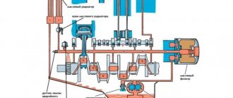
Fig.32. Diesel fuel coarse filter YaMZ-236 1–spring washer; 2–bolt; 3 – plug gasket; 4–cork; 5–lid; 6–cap gasket; 7–cap; 8–filter element; 9–drain plug; 10–drain plug gasket Replacing the coarse fuel filter element of the YaMZ-236 diesel engine Drain the sediment from the filter. Unscrew the four bolts 1 (Fig. 33) securing the filter cap 8 to the cover 5, remove the filter cap and remove the old filter element 7. Thoroughly rinse the internal surfaces of the cap with clean gasoline or diesel fuel. Place the new element 7 and gasket 6 in the groove of the cover, install the cap, and, making sure that the gasket is in the correct position (without displacement), carefully tighten the bolts 1 securing the cap to the cover. If access to the filter is difficult, to avoid cases of gasket displacement, it is permissible to lubricate the gasket on the cover side at several points with grease before installation. Unscrew plug 3, pour clean fuel into the filter and tighten the plug carefully. Start the engine and make sure the filter is tight. Tighten the bolts and eliminate air leaks. Fig.33. Coarse fuel filter 1–fastening bolt; 2–washer; 3–cork; 4 – plug gasket; 5–lid; 6–gasket; 7–filter element; 8–cap; 9-drain plug YaMZ-236 diesel fine fuel filter The fine fuel filter (Fig. 34) consists of a cap 5 with a rod 6 welded to it, a cover 8 and a filter element 4. A drain plug 1 with a gasket 2 is screwed into the rod from below. The seal between the cap and the lid is ensured by a paronite gasket 7. The cap and the lid are connected by a bolt 12, under the head of which a sealing washer 13 is placed. The replaceable filter element is pressed against the lid by a spring 3. The filter element is sealed at the end surfaces with gaskets. Fig.34. Fine fuel filter for YaMZ-236 engine 1-drain plug; 2-drain plug gasket; 3-spring; 4-filter element; 5-cap; 6-rod; 7-cap gasket; 8-cover; 9-cork; 10-jet gasket; 11.15-valve-jet; 12-bolt; 13-gasket; 14-filter element gasket. A nozzle 12 is screwed into the cover, which is sealed with a gasket 10. Some of the fuel is drained through the nozzle along with the air that has entered the low pressure system. On engines equipped with an electric torch device, instead of a jet, a jet valve 15 is installed in the filter. At low pressure in the system, which can be observed during engine startup, fuel does not drain, and the fuel supply to the ECU is improved. Replacing the YaMZ-236 fine fuel filter element Drain the sediment from the filter. Unscrew bolt 5 (Fig. 35) securing the cap. Remove the cap 10 and remove the old filter element 8. Wash the internal surfaces of the cap with gasoline or clean diesel fuel. Place spring 9 in cap 10, filter element 8 (with the smaller hole down), and install a rubber gasket on the upper flange of the element. Fig.35. Fine fuel filter 1 – gasket; 2 – cover; 3 – jet gasket; 4 – jet; 5 – bolt; 6 – fastening bolt washer; 7 – cap gasket; 8 – filter element; 9 – spring, 10 – cap; 11 – drain plug gasket; 12 – drain plug; 13 – plug Place washer 6 of the fastening bolt and gasket 7 of the cap, install the cap with the element in place and carefully tighten bolt 5. To drain the sludge from the coarse and fine fuel filters, unscrew the drain plugs 3-4 turns and drain 0.1 at a time l of fuel into a substitute container. After draining the sediment, tighten the plugs and run the engine for 3-4 minutes to remove air pockets. Draining the sludge is especially important in the winter to remove condensing water. Engine fuel lines of the YaMZ-236 engine To supply fuel to the pump and injectors, as well as to remove its excess, the YaMZ-236 engine has a system of low and high pressure fuel lines. Low pressure fuel lines are connected with hollow bolts or union nuts through ferrules attached to the ends of the fuel lines. The contact surfaces are sealed with copper washers 1.5 mm thick. The high pressure fuel lines are the same length for all engine cylinders. The ends of the fuel lines are set in the shape of a cone and pressed with union nuts to the fittings of the high pressure fuel pump and injectors. To avoid damage to fuel lines due to vibration, they must be secured using special brackets. The operating order of the sections is different for different fuel injection pump models; therefore, the connection diagrams for the high-pressure fuel lines of the fuel injection pump sections and the injectors of the engine cylinders are different. Lubrication system of the YaMZ-236 diesel engine The lubrication system of the YaMZ-236 engine is mixed, with a “wet” sump (Fig. 36). The oil pump (Fig. 37), through a suction pipe with an intake, sucks oil from the crankcase and supplies it to the system through a series-connected liquid-oil heat exchanger (if equipped).
Fig.36. Diagram of the YaMZ-236 engine lubrication system with a single-section oil pump and liquid-oil heat exchanger 1-oil sump; 2–oil intake; 3–oil pump; 4–reducing valve; 5–liquid-oil heat exchanger; 6–oil purification filter; 7–bypass valve; 8-signal filter lamp; 9–centrifugal oil purification filter; 10–camshaft; 11–axis of pushers; 12 – crankshaft; 13–differential valve; 14–piston cooling nozzle; 15- throttle; 16–turbocharger; 17–heat exchanger bypass valve; 18–fan drive switch; 19–fan drive; 20–Fuel injection pump A bypass valve is installed in the heat exchanger body (plate). If the pressure difference before and after the heat exchanger reaches 274±40 KPa (2.8±0.40 kgf/cm2), the valve opens and part of the oil is supplied directly to the oil line. Next, through the tube and channels in the block, part of the oil through the bushing (throttle with a calibrated hole) flows to the piston cooling nozzles and then drains into the crankcase. On YaMZ-236N,B engines, instead of a throttle, a valve is installed that stops the oil supply to the injectors when the oil pressure in the lubrication system is below 300...350 kPa (3.0...3.5 kgf/cm2). The other part goes into the oil filter (Fig. 38). A bypass valve is installed in the filter housing. When the pressure difference before and after the filter reaches 200...250 kPa (2.0...2.5 kgf/cm2), the valve opens and part of the crude oil is supplied directly to the oil line. By the time the bypass valve begins to open, the moving and fixed contacts of the alarm will close. At this moment, a warning light connected to the signaling device terminal lights up in the driver’s cabin. This increase in pressure can occur when the filter element is clogged or the oil has a high viscosity (for example, when starting the engine in the cold season). Fig.37. Oil pump of YaMZ-236 engine 1–idler gear; 2 – intermediate gear axis; 3–drive shaft; 4–body cover; 5 – driven gear shaft; 6–body; 7– drive gear; 8–key; 9–thrust flange; 10-fitting (present only on engines without a water-oil heat exchanger); 11 – pressure reducing valve The filter element of the YaMZ-236 oil filter is made either of non-woven material stretched over a metal frame, or of special filter paper. From the filter, oil flows into the central oil channel, and from there, through a system of channels in the block, to the bearings of the crankshaft and camshaft. From the crankshaft bearings, through oil passages in the crankshaft and connecting rods, oil is supplied to the bearings of the upper ends of the connecting rods. From the diesel camshaft, oil is directed in a pulsating flow to the axis of the pushers, and from there, through the channels of the pushers, the cavities of the rods and rocker arms, it flows to all the rubbing pairs of the valve drive, and through the outer pipe to the bearings of the turbocharger, speed controller and high-pressure fuel pump. Fig.38. Oil filter of the YaMZ-236 engine 1–filter housing; 2–cap gasket; 3–lock cover; 4–filter cap; 5–filter element; 6–cap head; 7–filter element gasket; 8– valve plunger; 9–valve spring; 10–signaling spring; 11–moving contact of the signaling device; 12–fixed contact; 13–terminal The bearing of the intermediate gear of the oil pump drive is also lubricated under pressure. Unit drive gears, camshaft cams, rolling bearings, and cylinder liners are splash lubricated. A pressure reducing valve is installed in the pump housing, which transfers oil back to the crankcase when the pressure at the pump outlet is above: 700...800 (7.0...8.0 kgf/cm); To stabilize the pressure, a differential valve is included in the lubrication system of the YaMZ-236 engine, adjusted to the beginning of opening: 520...560 kPa (5.2...5.6 kgf/cm). The centrifugal oil purification filter (Fig. 39) is connected in parallel after the oil purification filter and passes up to 10% of the oil passing through the lubrication system. The purified oil is drained into the crankcase. Additional centrifugal oil purification is also carried out in the cavities of the crankshaft connecting rod journals. Fig.39. Centrifugal oil purification filter YaMZ-236 1 – filter cap; 2, 7 – washers; 3-cap nut; 4–rotor mounting nut; 5–thrust washer; 6–rotor nut; 8, 14 – rotor bushings; 9–rotor cap; 10–rotor; 11–reflector; 12–O-ring; 13–cap gasket; 15–rotor axis; 16–filter housing; 17–rotor nozzle; A – from the system under pressure; B – draining oil into the crankcase The radiator section of the two-section oil pump supplies oil to the air-oil heat exchanger (TDC) installed on the machine. The oil cooled in the heat exchanger is drained into the crankcase. The safety valve of the radiator section opens when the pressure at the pump outlet exceeds 100…130 kPa (1.0…1.3 kgf/cm2). On engines with TDC, a single-section oil pump can be used with division of the oil flow at TDC through a throttle with a safety valve of 100...130 kPa (1.0...1.3 kgf/cm2). Oil pressure is monitored in the central oil channel.
______________________________________________________________________________________
___________________________________________________________________________________________
Other special equipment
MTZ-80
- Creeper MTZ-80, 82
- Design of the chassis of the MTZ-80 tractor
- Gearbox MTZ-80
- Clutch MTZ-80, 82
- Maintenance and adjustment of the MTZ-80.82 gearbox
- Starting motor PD-10
- Transfer case MTZ-80
- Adjustments of drive axles MTZ-80, 82
- Steering gear and power steering MTZ-80, 82
- Braking system MTZ-80, 82
- PTO MTZ-80, 82
______________________________________________________________________________________
YaMZ-236
- Components of the YaMZ-236 HE2, BE2 cylinder block
- Clutch YaMZ-181,182,183
- Clutch discs YaMZ-236, 238
- Crankshaft and piston group YaMZ-236
- Gearbox YaMZ-236
- Diagnostics and adjustment of the YaMZ-236 engine
- Fuel supply and lubrication of the YaMZ-236 diesel engine
- Clutch YaMZ-236
- Injection pump and injectors YaMZ-236
YaMZ-238
- Cylinder block and piston group YaMZ-238
- Crankshaft and timing belt of diesel engine YaMZ-238
- Gearbox YaMZ-238
- Cooling and lubrication of diesel engine YaMZ-238
- Clutch YaMZ-238
- Fuel injection pump YaMZ-238
T-130
- Onboard clutches T-130
- Final drive T-130
- Diesel D-160 tractor T-130
- Undercarriage T-130
- Turning mechanism of the T-130 tractor
- Assembly and installation of T-130 trolleys
- Servomechanism of onboard clutches T-130
- Tractor clutch T-130
- Control mechanism for clutch and mountain brake T-130
T-170
- D-180 engine of T-170 bulldozer
- Hydraulic system of bulldozer T-170
- Hydraulic cylinder of bulldozer T-170, 130
- Repair of the main gear of bulldozer T-170, 130
- Tracks and rollers T-170, 130
- Carrying and running system T-170
- Assembly of gearbox units T-170, 130
- Tension mechanism and support roller T-170, 130
- Bulldozer equipment T-170 with rotary blade
- Adjusting the T-170 clutch
- Transmission parts for bulldozer T-170
KRAZ
- Gearbox KRAZ-255, 260
- Steering of Kraz-250, 255
- Drive axle and cardan shafts Kraz-255, 260
- Clutch Kraz-250, 260
- Power steering of the Kraz car
- Kraz car suspension
- Kraz transfer case
- Kraz power take-off
- Brake system for Kraz-6510, 65055 vehicles
- Cardan transmission and drive axles Kraz-6510, 65055
- Front suspension of Kraz-6510, 65055 cars
- Steering KRAZ-6510, 65055
- Clutch Kraz-6510, 65055
How the YaMZ-236 model was created and production today
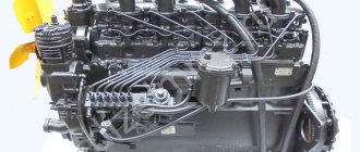
Before the development of this engine, YaAZ models were used, which became obsolete by the fifties. Therefore, in the 50s of the last century, the Yaroslavl plant, under a state special order, was tasked with creating a more powerful and economical engine. In addition, we needed a unit that could be installed on a wide variety of equipment.
The development of the YaMZ-236 engine was undertaken by the honored scientist and outstanding designer of the USSR G.D. Chernyshev, who also developed other diesel engines in those years.
This is how a new internal combustion engine was born, which later became a celebrity. It was distinguished by high power, reliability and easy repairs, simple maintenance and cheap spare parts. With proper use, this mechanism will last for many years.
YaMZ-236 is still produced today, regularly modernized and at the same time already has a successor - an improved modification, YaMZ-530.
YaMZ-236 diesel engines are still relevant, their sales are not falling, despite the appearance of more modern models.
Scheme of operation of the fuel supply equipment of a YaMZ diesel engine
The fuel supply equipment of the YaMZ diesel lubrication system consists of the following main components:
Oil filter for YaMZ-236 engine
- a pump that supplies fuel under high pressure;
- fuel supply corrector;
- fuel pump;
- nozzles;
- coarse and fine fuel filters;
- fuel wires.
Some engines may have an injection advance clutch.
The operating scheme is as follows: the fuel pump takes fuel from the tank, and it passes alternately through both cleaning filters. After this, the diesel fuel, cleaned of contaminants, is sent to a high-pressure pump.
It sprays fuel through pipelines and nozzles in the cylinders, according to their operation algorithm. Excess fuel is removed through a bypass valve and a nozzle in a “thin” filter, they are drained back into the tank. Excess air also goes there.
Oil pump pressure reducing valve - what is it and what is it for?
A car engine cannot function normally without constant lubrication with engine oil: parts will heat up from excessive friction and quickly become unusable. In order to ensure constant lubrication of all necessary elements, a design such as an oil pump was developed. It is he who is responsible for the supply and distribution of the lubricant.
However, here you need to pay attention to one important point: if the oil flowed freely, solely under the influence of gravity, many remote and hard-to-reach parts would not receive their share of lubrication and would run dry. On the other hand, too much pressure inside the pump would also increase wear on a number of elements. Oil seals and gaskets especially suffer from this, because due to the strong flow pressure they become thinner and begin to leak oil through themselves.
From all of the above, it is easy to conclude that the oil pump needs a special device responsible for maintaining stable pressure inside the system. Based on this feature, all pumps are divided into two categories:
The first type regulates pressure by changing the position of a certain part of the pump. But in the second, this function is performed by a pressure reducing valve. This is what we will talk about in more detail.
Reduction (from lat. reductio return bringing back) - simplification, reduction of the complex to something simpler, more visible, understandable, more accessible for analysis or solution; decrease, weakening of something.
Big Encyclopedic Dictionary
As the name of this device suggests, the main purpose of the pressure reducing valve is to normalize the pressure inside the oil pump system. That is, it reduces or increases pressure at the right time.
Reducing valve location
The oil pump itself is hidden under the hood of the car. To find out where your pump is located, check your vehicle's owner's manual, as the relative positions of the elements may vary depending on the make and model. For example, in a number of VAZ cars it is located behind the crankshaft pulley, so it is not immediately noticeable. As for the regulator, there are two options for the location of the device:
When located externally, the valve has its own body, which is located on the oil line. And with an internal pressure regulator, it is located directly inside the pump.
Design and principle of operation of a pressure reducing valve
The pressure reducing valve has a fairly simple structure. It consists of the following parts:
- ball (element No. 1 in the figure);
- spring (No. 2);
- thrust bolt (No. 3).
This device allows the valve to move, opening and closing the flow into the system under the influence of pressure. All elements are located inside a protective casing, which also has channels for the circulation of the lubricant.
The operating principle of this mechanism is to maintain the required pressure inside the pumping system. When it becomes significantly higher than the permissible level, the oil acts on the thrust bolt, which compresses the spring. The valve is squeezed out and an additional channel opens, through which excess oil is discharged into a special tank.
Frequent malfunctions of the Yamz 238 engine
Let's consider cases when the engine does not start, or starts with difficulty. If the engine does not start, you need to check the presence of fuel in the tanks. If not, fill the tanks with fuel and bleed the fuel system to remove air from it. The pumping is done by a fuel booster pump. Before pumping, unscrew the air bleed plug on the engine.
Pumping is carried out until the fuel begins to come out without air bubbles. The diesel fuel used for the engine must be in accordance with GOST 4749-49. The use of sulfur fuel (GOST 305-62) in engine operation is allowed, but it is necessary to use diesel oil with the VNII NP-360 -6% additive. In winter, Dz and Z fuel is used, and in summer, DL or L. At very low temperatures, it is recommended to use YES or A fuel.
It is advisable to use Dp-8 oil in winter. Dp-11 is used in the summer using additives VNII NP-360 or CIATIM-339.
Characteristics of YaMZ 238 filling containers
The YaMZ 238 engine uses a mixed-type lubrication system with a “wet” sump.
You can find out how much oil will need to be poured into the YaMZ 238 engine based on the size of the unit’s filling tanks. In particular, the lubrication system has a volume of 32 liters of oil.
The engine cooling system without a radiator requires 20 liters of lubricants. The fuel pump needs 0.2 liters, the air filter capacity is 1.4 liters. The 238 model, unlike the 236, does not have a regulator.
The oil volume in the YaMZ 238 engine is measured using a special dipstick with o and “minimum”. 24-28 liters are poured at a time, despite the fact that the working volume of the lubrication system of this power unit reaches 32 liters. if during operation the oil pressure in the system is increased to more than 520 kPa (5.2 kgf/sq.cm), excess lubricants are returned through the oil line and simultaneously cleaned by filters.
Oil pump of YaMZ-236M2 engine
| № | Catalog number | Quantity | Name |
| 1 | 236-1011230-A | 1 | Driven gear |
| 2 | 236-1011217-B2 | 1 | Thrust flange |
| 3 | 310254-P2 | 2 | Bolt |
| 4 | 252136-P2 | 2 | Washer |
| 5 | 236-1011380 | 2 | Adjusting gasket |
| 6 | 236-1011014-VZ | 1 | Oil pump |
| 7 | 236-1011202-A | 1 | Intermediate gear |
| 8 | 252137-P2 | 2 | Washer |
| 9 | 310156-P2 | 2 | Bolt |
| 10 | 314005-P2 | 1 | Key |
| 11 | 236-1011040-B | 1 | Discharge section driving gear |
| 12 | 201-1015434 | 1 | Ball |
| 13 | 236-1011100 | 1 | Radiator section driving gear |
| 14 | 236-1011019-B | 1 | Radiator section housing |
| 15 | 252135-P2 | 12 | Washer |
| 16 | 200270-P2 | 6 | Bolt |
| 17 | 236-1011015-G | 1 | Discharge section housing |
| 18 | 236-1011352-B | 1 | Discharge pipe of the discharge section |
| 19 | 236-1011030-B | 1 | Driven gear of the discharge section |
| 20 | 236-1011114 | 1 | Driven gear of the radiator section |
| 21 | 236-1011049 | 1 | About the rate |
| 22 | 240-1011057 | 1 | Valve spring |
| 23 | 236-1011056-A | 1 | Differential valve |
| 24 | 236-1011358-A | 2 | Pad |
| 25 | 312559-P2 | 1 | Washer |
| 26 | 236-1011368-B | 1 | Safety valve spring |
| 27 | 236-1011363-B | 1 | Radiator section safety valve |
| 28 | 236-1011420-B | 1 | Radiator section outlet pipe |
| 29 | 201457-P2 | 2 | Bolt |
| 30 | 201458-P29 | 4 | Bolt |
| 31 | 314537-P | 1 | Square |
| 32 | 236-1011098-BZ | 1 | Differential valve supply pipe |
| 33 | 314612-P29 | 1 | Union |
| 34 | 236-1011320 | 1 | Suction pipe mounting bracket |
| 35 | 310248-P2 | 2 | Bolt |
| 36 | 258013-P29 | 2 | Cotter pin |
| 37 | 236-1011398-G | 1 | Suction tube with intake |
| 38 | 236-1011322 | 1 | Bracket |
| 39 | 250975-P2 | 2 | screw |
| 40 | 201495-P2 | 2 | Bolt |
| 41 | 236-1011296 | 1 | Pad |
| 42 | 236-1011048-B | 1 | Pressure section pressure reducing valve |
| 43 | 236-1011058-B | 1 | Valve spring |
| 44 | 312571-P2 | 1 | Washer |
| 45 | 236-1011208-B | 1 | Idler gear axis |
| 47 | 236-1011399-B | 1 | Suction tube with intake |
yamz-td.ru
Design of the coarse filter for the YaMZ 236 engine
The main detail of its design is a filter element made of coarse fleecy cotton cord. It is wound onto a metal mesh base and fixed between the lid and the bottom of the case. The body of the device is a cap or flask in which a layer of wound cord is placed. Fuel is supplied from above, and purified fuel also exits from above. There is a drain hole at the bottom of the structure.
Cotton cord is a consumable, replaceable material.
Coarse fuel filter for YaMZ-236 engine
Fine filter device
Constructed from a housing-cap, an internal rod, a cover and a replaceable filter element. The latter is pressed against the lid from the inside by a spring. It is sealed at both ends with gaskets. The lid contains a jet or (on engines with an electric torch device) a special valve through which excess air-fuel mixture is removed.
At the bottom of the structure there is a drain hole with a plug.
Fine filter for diesel fuel YaMZ-236
Functions of fuel lines
High-pressure fuel lines in the engine are arranged according to different typologies, since the operating algorithm of the sections is different for different fuel injection pump models. But they all have the same length. The ends of the high pressure fuel wires are crimped into cones and connected to the fittings of the corresponding fuel pump.
The low pressure fuel lines of the engine are secured in the corresponding units with union nuts or “empty” bolts through the ends. The contacts are sealed using thick-walled copper washers.
Fuel injection pump YaMZ 236
Oil pump of YaMZ-236M2 engine
| № | Catalog number | Quantity | Name |
| 1 | 236-1011230-A | 1 | Driven gear |
| 2 | 236-1011217-B2 | 1 | Thrust flange |
| 3 | 310254-P2 | 2 | Bolt |
| 4 | 252136-P2 | 2 | Washer |
| 5 | 236-1011380 | 2 | Adjusting gasket |
| 6 | 236-1011014-VZ | 1 | Oil pump |
| 7 | 236-1011202-A | 1 | Intermediate gear |
| 8 | 252137-P2 | 2 | Washer |
| 9 | 310156-P2 | 2 | Bolt |
| 10 | 314005-P2 | 1 | Key |
| 11 | 236-1011040-B | 1 | Discharge section driving gear |
| 12 | 201-1015434 | 1 | Ball |
| 13 | 236-1011100 | 1 | Radiator section driving gear |
| 14 | 236-1011019-B | 1 | Radiator section housing |
| 15 | 252135-P2 | 12 | Washer |
| 16 | 200270-P2 | 6 | Bolt |
| 17 | 236-1011015-G | 1 | Discharge section housing |
| 18 | 236-1011352-B | 1 | Discharge pipe of the discharge section |
| 19 | 236-1011030-B | 1 | Driven gear of the discharge section |
| 20 | 236-1011114 | 1 | Driven gear of the radiator section |
| 21 | 236-1011049 | 1 | About the rate |
| 22 | 240-1011057 | 1 | Valve spring |
| 23 | 236-1011056-A | 1 | Differential valve |
| 24 | 236-1011358-A | 2 | Pad |
| 25 | 312559-P2 | 1 | Washer |
| 26 | 236-1011368-B | 1 | Safety valve spring |
| 27 | 236-1011363-B | 1 | Radiator section safety valve |
| 28 | 236-1011420-B | 1 | Radiator section outlet pipe |
| 29 | 201457-P2 | 2 | Bolt |
| 30 | 201458-P29 | 4 | Bolt |
| 31 | 314537-P | 1 | Square |
| 32 | 236-1011098-BZ | 1 | Differential valve supply pipe |
| 33 | 314612-P29 | 1 | Union |
| 34 | 236-1011320 | 1 | Suction pipe mounting bracket |
| 35 | 310248-P2 | 2 | Bolt |
| 36 | 258013-P29 | 2 | Cotter pin |
| 37 | 236-1011398-G | 1 | Suction tube with intake |
| 38 | 236-1011322 | 1 | Bracket |
| 39 | 250975-P2 | 2 | screw |
| 40 | 201495-P2 | 2 | Bolt |
| 41 | 236-1011296 | 1 | Pad |
| 42 | 236-1011048-B | 1 | Pressure section pressure reducing valve |
| 43 | 236-1011058-B | 1 | Valve spring |
| 44 | 312571-P2 | 1 | Washer |
| 45 | 236-1011208-B | 1 | Idler gear axis |
| 47 | 236-1011399-B | 1 | Suction tube with intake |
yamz-td.ru
Tuning of YaMZ-238 engines
How to install a turbine
To convert a regular naturally aspirated 238 into a turbo, you can leave standard pistons, you can do without oil nozzles, just install a TKR 36-87 turbine with manifolds from YaMZ-7511, make an oil drain and oil supply to the turbine, install 261 nozzles, adjust the fuel injection pump and drive as is. This way you can get 280-300 hp. It will even run for years without problems, but for higher reliability it is better to replace the pistons with 238B.
<<BACK
Maintenance of the YaMZ-236 diesel engine
Maintenance of this mechanism is quite simple, as mentioned above. To do this, you just need to understand its design. Most often required:
- change the oil (this requires lubricant for a diesel engine);
- replace filter elements (filters require replacement every 15 thousand kilometers);
- blow out the injectors (i.e. adjust the injection);
- replace valve cover gaskets;
- tighten or replace drive belts.
These are the main points of engine maintenance. Other problems require repair. This will require special equipment, so all work is usually carried out only in a car service center.
Reviews about the power unit
Due to the diverse application and long period of use, the following main points can be highlighted in reviews of engine operation:
- Good reliability.
- Low fuel consumption of the YaMZ-238 engine.
- Possibility of use on various types of equipment.
- Low vibration of the running engine.
- Qualitative technical characteristics of the YaMZ-238 engine.
- High maintainability.
- Use of inexpensive domestic consumables: motor oil, process fluids, greases.
- Affordable price YaMZ-238 (from 350 thousand rubles).
- Availability of spare parts.
The existing advantages and high-quality technical characteristics of the YaMZ-238 engine ensure the current demand for the power unit among manufacturers of various types of transport vehicles and equipment.
YaMZ-236 on the modern market: the cost of these engines and reviews about them
The price for a new naturally aspirated engine YaMZ-236 ranges from 370 to 450 thousand rubles; for YaMZ-236 with turbocharging - from 480 to 650 thousand rubles. From time to time the opportunity arises to purchase YaMZ-236 a little cheaper: from the storage of the State Reserve, new, in pallets. At half the price of a new one, you can find used YaMZ-236 or individually assembled motors (after overhaul) on ad sites.
For the modern development of technology, YaMZ-236 diesel engines have rather mediocre specific performance and efficiency indicators. The design, outdated over the past half century, does not allow these engines to comply with Euro-3 standards and higher. The turbocharged versions were modified to Euro-2 standards.
Modern Rostov Vector combines are equipped with a YaMZ-236ND motor
However, their unsurpassed reliability and unpretentiousness; the low price (compared to imported analogues) for the motors themselves and spare parts for them helps maintain stable demand for these products. Reviews about the YaMZ-236 boil down to one thing: fuel consumption, by today's standards, is high, but the reliability is simply excellent. Even in large ATPs, where bus drivers periodically change and there is no need to talk about careful handling of equipment, YaMZ-236 engines honestly work out the resource declared by the manufacturer of 800 thousand kilometers. And they continue to work, without serious breakdowns, without requiring major repairs for a long time.
Oil pump pressure reducing valve failure - repair or replacement?
Repair work begins with disassembling the pressure reducing valve. Removing the cover and removing the spring is not difficult, but removing the valve itself usually becomes difficult. In order to do this, you will need the following tools:
- anchor bolt M8 (length 90 mm);
- nut for wrench 10;
- open-end wrench.
The anchor must be inserted tightly into the plunger, and then the nut must be screwed onto it. After this, take the wrench and continue tightening the nut. After some time, the piston will break off and you can remove it.
In the absence of the above tools, some craftsmen come up with their own ways of dismantling the valve.
Video: how to remove the valve using a wooden stick
The repair of this mechanism itself depends on the cause of the breakdown. If the problem was low pressure, you should replace the spring. It is very important to find the same part that was before. Please note that the sizes of pressure reducing valves and their components differ for different car models. We recommend that you consult with a specialist before purchasing the part, and come to the store with a disassembled mechanism.
If the valve becomes clogged and stops reducing pressure inside the oil pump, carry out the following procedures.
- Clean the part thoroughly, paying particular attention to the oil passages.
- Wash the mechanism in gasoline.
- Lubricate the dried part.
- Place the valve in its place.
- Now you need to check the pressure. For this, a conventional pressure gauge is used. The hose with a threaded fitting must be screwed into place of the standard pressure sensor, and then start the engine. You need to find out the values acceptable for your car in the engine manual. For most cars they range from 1 to 4.5 kg/cm2 at medium speeds.
Typically, experts recommend replacing the valve if major repairs have been carried out before. It is believed that ordinary cleaning and rinsing cannot cope with small chips. It is also worth replacing if you find mechanical damage on the surface of one of the valve components.
Repairing and replacing the pressure relief valve affects the overall performance of the vehicle. And this is not only clearly visible, but also clearly audible while the engine is running.
Video: differences in engine sounds before and after replacing the pressure relief valve
Before disassembling the oil pump and its pressure relief valve and carrying out any work on them, make sure that you are confident in your own abilities. Inaccurate actions can lead to final failure of parts. It will be especially disappointing if the problem was not in the valve, but in other elements of the system, and you have to change a working part. If in doubt, it is better to seek the help of specialists at a car service center.
Source of the article: https://autoclub.su/redukcionnyj-dvigatel-maslyanogo-nasosa-ustrojstvo-i-remont-neispravnostej/
Fuel traffic assessment
- the fuel in the chamber begins to move;
- the marks on the rotary wheel casing coincide with the line whose value coincides with the number on the end of the OVT coupling;
- the mark on the crankshaft pulley is opposite the line with a similar number on the timing gear housing.
If at the time of the start of fuel movement in the chamber this coincidence of marks is not yet present, you need to:
- unscrew the mounting bolts;
- turn the motor shaft coupling half on the flange in the opposite direction of torsion;
- retighten the mounting bolts;
- check the position of the UOVT again.
Features of the mechanism
In order for the mechanism to work smoothly and for a long time, you need to know and observe certain features.
First of all, it is necessary to carefully carry out all routine maintenance provided for in the manufacturer’s instructions.
When running in a new engine, all its rubbing surfaces are run-in, so it is important to follow the running-in rules - they are usually indicated in the corresponding section of the instructions.
It is also important to lubricate the engine according to the appropriate table. All approved lubricants are listed in it.
The coolant in a running engine should have a temperature of 75 to 98 degrees. A cold engine should not operate under load. When starting a cold engine, you cannot sharply increase the speed, as the thick oil does not have time to reach the crankshaft bearings, and they fail.
The oil level should not fall below 300 kPa, otherwise the rubbing surfaces may quickly wear out.
Cylinder head fastenings that are tightened with nuts must be tightened with strict frequency, sequence and specified torque. If this is not observed, the seal will fail and the gaskets will burn out.
Operation of the MAZ oil pressure sensor
Indispensable is designed to operate at temperatures from – 40 to + 150 degrees. The device transmits accurate data even in extreme conditions.
The maximum deviation is 0.5%.
The MAZ oil pressure sensor can withstand loads of up to 3.5 MPa. The device may be used during vibration.
The service life is about 12,000 hours.
Cooling and power system
Maintaining temperature conditions is an indispensable condition for ensuring the technical characteristics of the YaMZ 236 engine. Fuel and oil consumption, as well as engine durability, directly depend on the engine temperature. To maintain temperature conditions, the engine is equipped with a radiator with a special valve that allows you to increase the boiling point of the coolant to 116-119 degrees.
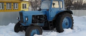
The liquid is cooled by a six-bladed fan driven by the gears of the gas distribution mechanism. An intermediate drive pulley for the generator and compressor of the pneumatic brake drive system is installed on the fan shaft on bearings. The fan is installed in a special casing that directs the air flow. The cooling intensity is regulated by manually operated blinds installed in front of the radiator from the driver's cabin. The engine is connected to the radiator by rubber hoses. The total capacity of the system is 28 liters. The photo in the article shows a general view of the YaMZ 236 with a turbocharger and gearbox.
The operating temperature of the engine is a range of values between 75-98 degrees. Each cylinder block has its own fluid drainage channel, equipped with a thermostat. The manufacturer does not recommend long-term engine operation at coolant temperatures below 60 degrees. Temperature control is carried out using a device on the dashboard in the driver's cabin.
Optionally, a heater model PZhD 400 or 44 can be installed in the cooling system. The heater is installed in front of the radiator and is based on heating the liquid with fuel burning in the boiler. There are special channels for installing a heater in the YaMZ 236 engine block. Liquid circulation is carried out by a separate pump with an electric drive. Exhaust gases are diverted to the oil pan to heat the oil. The use of an autonomous heater improves the operational and technical characteristics of the YaMZ 236. Fuel consumption when using such a system is noticeably lower, especially when operating a diesel engine at low temperatures.
Design of the MAZ oil pressure sensor
There is a thin membrane inside the unit.
When the ignition is turned on, the device contacts are closed. There is no pressure. When the engine starts, an impact occurs on the membrane.
The part becomes deformed over time and moves the pusher.
The spare part breaks the contacts and opens the electrical circuit. The indicator lamp goes out. If the pressure in the system drops, the membrane returns to its original position. The pusher completes the circuit. The light comes on.
It’s easy to buy a MAZ oil pressure sensor on our website. Choose a measuring device:
- With plug connectors protected from moisture and dust;
- With thermally insulated cable;
- With O-rings to protect the interior from dirt.
The durable housing of the MAZ oil pressure sensor is resistant to damage. Thanks to the reinforced design, even if the tightening torque is exceeded, the device will not deteriorate.
Assembly after repair
After the pump has been completely disassembled, the fault has been identified, all damaged elements have been replaced with new ones, all working parts should be washed and then dried thoroughly. You can use compressed air for this.
Next, you need to assemble the product for further installation on the car engine. To do this, you need to perform a number of operations:
- Press the bearings and water release onto the shaft. In this case, the shaft should be lubricated with diesel engine oil. The bearings must be installed so that the sealing washers are on the outside. All pressing force must be applied only to the inner ring of the bearings.
- Next, it is necessary to fill the open cavities between the bearings, formed after pressing, with special lubricant “Litol-24.
- Lubricate the shaft with previously unused engine oil.
- During the next operation, the shaft assembly must be installed in the water pump housing. It is necessary to provide a fixed stop on the opposite side of the shaft.
- Next, you need to install a mechanical seal made of a brass body.
- Place a rubber cuff assembled with a spring and several frames.
- Next, you should put the cuff on the sealing sleeve.
- Then it is necessary to lubricate the pulley bore with a thin layer, as well as the outer surface of the cuff, which is made of rubber.
- Install the reinforced collar and bushing for sealing.
- Mount the pulley in the rubber collar and bushing for sealing. To avoid various distortions and the occurrence of gases in the YaMZ-238 cooling system, you need to clasp the cuff with both hands and then insert it into the pulley bore.
- Next, you need to press the pump pulley assembly onto the shaft, but before that you should remember to lubricate both parts at the contact points with previously unused engine oil.
- Secure the pulley to prevent it from rotating.
- Screw the cap tightly.
- Install a rubber ring and bushing into the water pump housing.
- Place a ring in the groove of the pipes.
- Connect the pipes of the YaMZ-238 cooling system to the pump.
- Secure the pipes using hardware.
This completes the assembly of the water pump.
Oil pump YaMZ-7511
________________________________________________________________
Oil pump YaMZ-7511
Dismantling the YaMZ-7511 oil pump
Clamp the oil pump housing in a vice by its surfaces, having previously installed protective plates on the jaws of the vice so as not to damage the pump housing.
Unscrew the thrust flange and remove it (S=46). The flange has a left-hand thread and must be unscrewed in the direction of the arrow.
Remove the intermediate gear.
Using a puller, compress the oil pump drive gear and remove the key. If necessary, clean the edges of the keyway.
Unscrew the bolts securing the idler gear axis and remove it (S=17).
Unscrew the mounting bolts and the oil pump housing cover with bushings as an assembly. Remove the drive shaft and driven shaft from the oil pump housing.
Disassemble the pressure reducing valve by unscrewing the plug (S=32) and removing the washer, spring, valve, and gasket from the body.
Assembly of the YaMZ-7511 oil pump
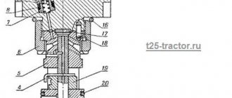
Fig. 7 – Pressure reducing valve
1–body; 2–valve; 3–spring; 4–cork; 5–gasket; 6-washer.
Assemble the pressure reducing valve (Figure 7), to do this, insert the spring, valve, washers into the body, install the gasket and screw in the plug.
Beginning of valve opening pos. 2 should occur at an oil pressure in cavity A of 7+1.0 kgf/cm2. Adjustment is ensured by installing the required number of washers, pos. 6. Tighten the plug pos. 4 produce with Mkr = 70-80 Nm (7.0-8.0 kg/cm).
Insert the driven shaft-gear into the oil pump housing, install the oil pump housing cover with the bushings as an assembly, tighten the fastening bolts (S=12).
Install the idler gear axle onto the housing and secure it with bolts (S=17).
Insert the key and press on the oil pump drive gear.
Place the intermediate gear (Figure 16, item 1) onto the axle. Screw the thrust flange into the idler gear. The flange has a left-hand thread, and it must be screwed from right to left (S=46).
The following requirements must be met during assembly:
— Mount the assembly unit, thrust flange, on sealant UG-9 TU 6–01–1326–86.
— Apply sealant in an amount of 0.15-0.25 g to the lead-in part of the thread of the idler gear axis of the drive.
— It is allowed to use sealant UG-6 TU 6 – 01 – 1285 – 84.
Assembly of the YaMZ-7511 oil pump with pipes
Lubricate the ends of the bolts (M8, 206513-P2, 2 pcs.) securing the intake cup (238F-1011300-A) with sealant, install it in the hole of the intake cup and screw 2-3 turns of thread into the holes of the suction pipe flange (238F-1011400-G ) by hand. Wrap completely (S = 12).
Assemble the bolts (M8, 201458-P29, 2 pcs.) securing the suction tube with the intake assembly (238-1011398-B2) with washers (8, 252135-P2, 2 pcs.), install the bolts into the holes in the flange of the suction tube with the intake , install the gasket (236-1011296) on the bolts, install the tube, tighten the bolts 3-4 turns of thread by hand.
Install bolts (M8, 200274-P29, 2 pcs.) with spring washers (8, 252135-P2, 2 pcs.) into the holes of the pressure reducing valve (238B-1011048, 1 pc.), install a gasket on the bolts (236-1011126, 1 pc.) and the outlet pipe (238B1011350-B) to the oil pump, screw in the mounting bolts 2-3 turns of thread by hand.
Install the intake mesh and secure it in the intake cup with a hook (204A-1011318-B).
Installation of oil pump YaMZ-7511
Assemble the mounting bolts (M10, 310254-P2, 2 pcs.) of the oil pump with washers (10, 252136-P2, 2 pcs.), install the bolts in the mounting holes of the oil pump, install 1-2 shims (236-1011380, 2 pcs.) onto the oil pump pins, screw the bolts into the block 2-3 turns by hand.
It is allowed to install no more than 2 shims between the pump housing and the crankshaft main bearing cover. Finally tighten the oil pump mounting bolts with Mkr = 90-100 Nm (9-10 kg/cm) (S = 14).
Rotate the circumferential clearance in the engagement of the crankshaft gear with the intermediate gear of the oil pump at three points when the engine is in operating position.
The gap should be within 0.25-0.37 mm. It is allowed to check the gap in a vertical position of the engine; the gap should be 0.22-0.38 mm. A gap of less than 0.25 mm and more than 0.37 mm must be adjusted by changing the number of plates.
Wrap the fitting (K 1/4″) into the block by 2-3 threads by hand.
Sequentially tighten the bolts (314681-P29) securing the suction tube with the intake and the outlet tube finally (S=12).
Connect the connecting tube of the differential valve (238B-1011098, 1 pc.) to the valve fitting (314681-P29) first manually using a bolt (M14, 310096-P2, 1 pc.) and washers (312326-P34, 2 pcs.).
Install the outlet tube until it stops in the holes of the flange and differential valve, having first checked the presence of O-rings in the valve flange.
Assemble the bolts (M8, 200270-P2, 2 pcs.) securing the valve with washers (252135-P2, 2 pcs.), install the bolts into the valve hole, screw the bolts through the gasket (236-1011358-A) into the block by 2-3 threads of carving by hand.
Insert bolts (M8, 200270-P2, 2 pcs.) with spring washers (252135-P2, 2 pcs.) into the holes of the flange, install the flange on the cylinder block, placing a gasket (236-1011358-A), screw the bolts into the holes of the block manually.
Screw the bolts securing the flange and differential valve into the block completely (S=12).
Screw the fitting into the block completely (S=19).
Install a sealing washer (312236-P34, 1 pc.) on the bolt (M14, 310096-P2, 1 pc.), insert the bolt into the hole in the connecting pipe, install a sealing washer (312236-P34, 1 pc.) on the bolt and screw it in manually into the fitting.
Completely tighten the bolts securing the connecting pipe.
Rotate the crankshaft to check that the connecting rod cap is not touching the tube.
avtodisel.ru
Common motor problems
The main breakdowns that are inherent in YaMZ-238 engines are considered typical for most diesel units. To eliminate problems with motors, it is necessary to identify the original cause. Usually this:
- Violations of technical requirements: use of poor fuel or low quality lubricants.
- Operational damage: clogging of the cooling system radiator with dirt, crushing of the oil pan, loosening of certain connections, violation of the ignition timing, as well as problems with the turbine.