Related Articles
Types and applications of belt conveyors
October 30, 2020
The advantage of 3D printing
February 28, 2020
Hydraulic excavator
February 25, 2020
On construction sites, it can be difficult to get by with standard solutions and machines such as bulldozers and tractors. In some cases, their use requires the addition of special devices, for example, trailed graders. They have a very limited scope, however, their use is not often abandoned.
Where are trailed graders used?
Graders towed by tractors were created as earth-moving machines for forming road surfaces and preparing the surface for laying asphalt and concrete. Trailed units are also used in the construction of industrial buildings, social infrastructure facilities, in agriculture and public utilities:
- for creating embankments, profiling their surface;
- in leveling road surfaces in dirt and embankment;
- when mixing crushed stone, gravel materials, soils of various categories with each other and with binding additives;
- for planning according to design marks of land plots, slopes, excavations, ditches;
- in distribution over the surface of the working area and leveling the layer of crushed stone, gravel, sand materials;
- when working in the public sector, including snow removal and garbage collection.
In all work where it is necessary to level the surface and make it uniform, the use of grader devices is effective and economically justified.
Based on the weight of the machine, there are light, medium and heavy motor graders. The wheel arrangement adopted for the chassis is determined depending on the wheel formula A X B X C, where A is the number of axles with steered wheels, B is the number of drive axles, C is the total number of axles. Light auto graders can have a wheel arrangement of 1×2×3 and 1×2×2; medium - 1 X 2 x 3 and 2x2x2, heavy - 1x2x3, 1x3x3 and 3x3x3. The most widespread are motor graders of all sizes with a 1×2×3 wheel arrangement.
The drive of the blade blade control mechanisms can be mechanical or hydraulic. Based on the type of transmission, motor graders are distinguished with mechanical and hydromechanical transmission. To rotate the steered wheels, motor graders are equipped with either hydraulic or mechanical steering. Mechanical control is often equipped with a hydraulic or pneumatic booster.
Table 1 Technical characteristics of graders
Notes: 1. Based on the DZ-99-1 model, modifications with manual control DZ-99-1-4, with automatic systems “Profile 1” DZ-99-1-2 and “Profile 2” DZ-99-1 can be produced -1, with a 60 hp engine. With. DZ-99-22 in a similar design, with a hydromechanical transmission DZ-99A-1-4. 2. Based on the DZ-31-1 model, modifications with a hydromechanical transmission (DZ-31-2) can be made. 3. Based on the DZ-98 model, modifications DZ-98-1 with a 165 hp engine can be produced. With.
Trailed graders for working with tractors should be made of two types: I - designed to work with a traction force of 3-4 tf at a speed of 2-4 km/h; II - designed to operate with a traction force of 10-12 tf at a speed of 2-3.5 km/h. The heavy grader DZ-1 (D-20BM) and the light grader DZ-b (D-241A) are commercially produced.
GOST 9420-69 provides for three types of motor graders: light - weighing Eti with a power of 75-90 hp. With. for patrol and planning work; medium - weighing 13 tons and power 120-150 hp. With. for grading, road reconstruction and on-site mixing of materials; heavy - weighing 19 tons and power 250 - 300 hp. With. for road construction and earthworks.
Currently, the following are mass-produced: - light motor grader DZ-99 (D-710B) in various modifications, including with a 90 hp engine. With; with manual control (DZ-99-1-4) with the “Profile 1” automation system (DZ-99-1-2), with the “Profile 2” automation system (DZ-99-1-2); - with a 60 hp engine. with: with the automatic system “Profile 1” (DZ-99-2-2), with manual control (DZ-99-2-4), as well as a modification with a 90 hp engine. With. with hydromechanical transmission (DZ-99A-1-4); medium motor grader DZ-31-1 (D-557-1) and its modification with hydromechanical transmission (DZ-31-2); — heavy motor grader DZ-98 (D-395V) and its modification with a 165 hp engine. With. (DZ-98-1).
The production of medium (DZ-122) and heavy motor graders with hydromechanical transmission (DZ-105) is being mastered.
Brief technical characteristics of graders and motor graders are given in table. 1.
—
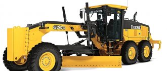
Motor graders are self-propelled machines equipped with a highly mobile blade, which has determined their widespread use for profiling and finishing the subgrade, erecting low embankments (up to 0.6 m) with soil supplied from lateral reserves, performing leveling and other work.
Depending on the power of the installed engine and the weight of the machine, motor graders are divided into four types: light (63 horsepower, 7-9 tons), medium (100 horsepower, 10-12 tons), heavy (160 horsepower). , 13–15 t) and especially heavy (250 hp or more, 17–23 t).1
Motor graders are also distinguished by the wheel pattern (formula) of the running equipment, denoted A X B X B (A is the number of axles with steered wheels; B is the number of axles with drive wheels: C is the total number of axles of the machine). The most common scheme is 1 X 2 X 3, but the following schemes are also used: for light motor graders 1x2x2, medium 2x2x2, heavy 1 x 3 X 3 and especially heavy 3x3x3.
Motor graders use mechanical and hydraulic control systems. The most common hydraulic system. In addition to the main working equipment - the blade, motor graders are equipped with additional equipment (blade extensions, slopes, pickers), as well as replaceable working parts (dozer blade, snow blower, road milling machine, etc.)
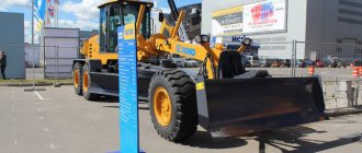
Light motor graders are used mainly for repair and maintenance of roads, medium ones - for building roads in light and medium soils and medium road repairs, heavy ones - for large volumes of road work, for grading large sites and working on heavy soils.
Motor graders are produced with a single design and consist (Fig. 136) of a main frame, a traction frame, a turntable with a blade, an engine, running equipment and a control system.
The main frame is equipped with a three-point suspension and consists of a front part made of steel pipe and a rear part consisting of two longitudinal members connected to each other.
The mounting brackets for the hydraulic cylinders for lifting and removing the blade are welded to the frame tube. The front axle, traction frame, bulldozer blade and control hydraulic cylinders are mounted at the front.
The engine, control cabin, transmission unit bracket and rear axle balancers are mounted on the frame side members.
The working bodies of the motor grader are activated as follows. From the engine, through the clutch, the movement is transmitted to the gearbox, and from it, through the main gear and final drives, to the road wheels.
The three-point frame suspension, the absence of a differential in the wheel drive mechanism and their combination into balancing bogies provide the motor grader with smooth movement on uneven surfaces, high maneuverability and good traction capabilities.
The traction frame of the DZ-40 motor grader is connected to the front head of the main frame by a ball joint and suspended from lifting hydraulic cylinders on ball pins, which ensures its mobility in two planes. By multidirectional activation of the lifting hydraulic cylinders, the traction frame with the blade is rotated up to 90°. The traction frame is moved in a horizontal plane (the blade is moved to the side) by a hydraulic cylinder connected (depending on the direction of removal) to one of the ball axles.
The ring gear turntable is suspended from the traction frame by three support shoes. It is centered with adjusting bolts 18. Using a hydraulic motor through a worm gearbox, the turntable with the blade can be rotated 360° in plan.
The motor grader blade is made of sheet steel. Removable knives are attached to the lower and side edges of its working side, and tubular rods are attached to the back side, grasped by the guides of the turntable brackets and gear combs.
Rice. 1. Motor grader DZ-61A with hydraulic control of working parts
Rice. 2. Kinematic diagram of motor grader D3-31
Rice. 3. Working equipment of the motor grader DZ-40
By turning on the hydraulic cylinder connected to the ball axle, the blade is moved across the traction frame, which increases its offset to the side.
By rearranging the ball pin on the blade, the offset can be increased.
The cutting angle in the range of 30-70° is adjusted by rearranging the toothed comb.
The picker attached to the turntable brackets, designed for preliminary loosening of dense and heavy soils, is fixed in the transport position with fingers.
To increase lateral stability, the driven axles of motor graders are usually equipped with a mechanism for tilting wheels in a vertical plane.
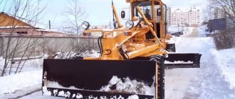
To work in difficult conditions (difficult profiles, clayey wet soils, etc.), graders attached to crawler tractors and equipped with hydraulic control of the working bodies continue to be used.
—
Motor graders are intended mainly for profiling work during the construction of roadbeds and railways. Motor graders can also perform a number of other jobs: planning airfield and construction sites; fill embankments up to 0.6 m high from lateral reserves, dig and clean ditches and ditches of trapezoidal and triangular profile, tear out and plan troughs for road bases; mix soil, crushed stone or gravel materials with binders - bitumen and cement, as well as destroy road surfaces, clean and level the slopes of embankments and excavations; clear streets and roads of snow.
Motor graders are classified by engine power and the corresponding machine weight, by the number of axles and type of wheel arrangement, and by the type of drive of working parts. The main parameter of these machines according to GOST 9420-69 is their weight, which determines not only the main indicators, but also the scope of application in road construction work.
The drive of the working parts of a motor grader can be mechanical, hydraulic or combined (pneumohydraulic). The most common are motor graders with volumetric hydraulic drive control.
The wheel layout, which characterizes the structural layout of the machine, is designated by the letters A-B-C, where A is the number of axles with steering wheels; B - number of driving axes; B is the total number of motor grader axles.
With an increase in the number of axles, the planning properties of the machine improve, an increase in the number of driving wheels increases the traction capabilities of the machine, and an increase in the number of axles with steered wheels increases its maneuverability. However, motor graders with the wheel arrangement 3X3X3 and 1X3X3 are structurally complex and expensive to manufacture, and therefore their production currently does not exceed 4% of the total number
A motor grader consists of a power plant, transmission, main and traction frames, working bodies, chassis and control mechanisms for working bodies and chassis. The latter include mechanisms for movement, raising and lowering the right and left ends of the blade, its rotation in the horizontal plane, moving the traction frame to the side, lateral movement of the blade, changing the cutting angle, tilting the wheels in the vertical plane and turning them in the horizontal plane. The front axle has a transverse balancer suspension. The rear wheels are paired with longitudinal-balanced suspension, which allows the motor grader to maintain good gliding properties when moving on uneven surfaces.
The working part of the machine is the blade. Sometimes it comes with replaceable equipment in the form of an extension and a slope, which are needed to increase the working width when finishing embankment slopes. The motor grader kit also includes a pickaxe, which is used to loosen old coating or soil. To perform various tasks with a motor grader, the position of the blade in the vertical and horizontal planes is changed.
The front wheels (for motor graders with all steerable wheels and the rear wheels) can tilt relative to the vertical axis, which makes the machine easier to operate on slopes and ensures its stability when planning slopes. The position of the blade is changed in the horizontal plane by rotating the turntable around its vertical axis, and in the vertical plane by raising or lowering the right or left ends of the traction frame. The blade can also be moved to the sides. To do this, the traction frame, to which the turntable is suspended, can be rotated in a horizontal plane by a special hydraulic cylinder (or mechanism) around the vertical axis of fastening its front point (hinge). The front wheels of the motor grader can tilt relative to their axis, which makes the machine easier to operate on slopes. The rear axles of the vehicle are suspended from the main frame by means of support balancers and reaction rods, the front axle is suspended by means of a king pin. The presence of a kingpin and balancers allows the motor grader to move smoothly over uneven terrain.
Rice. 4. Design diagram of a motor grader: 1 - ripper; 2, 5 — hydraulic cylinders; 3, 12 — cardan shafts; 4 - main frame; 6 — steering wheel shaft; 7 — cabin; 8 — engine; 9 - radiator; 10 — rear axle; 11 — clutch; 13 — gearbox; 14—dump; 15 — turntable; 16 — turntable frame, 17 — front axle axle; 18 — front axle
The main type of work for which the motor grader is intended is profiling the subgrade by successive passes along the planned surface. The working process of the machine consists of cutting out soil and moving it along the dump while moving the motor grader. The work process is completed in multiple passes with different blade settings.
To expand the scope of application and increase the time of use of the machine, throughout the year motor graders are equipped with replaceable working equipment for various purposes: bulldozers, snow plows and rotary plows, grader-elevator, road milling machine, cement distributor.
Internal combustion engines are usually used as power plants on motor graders. The transmission unit includes a multi-stage gearbox, transfer case, range, main gear and balancer gearboxes, which provides up to ten operating and transport speeds. They produce motor graders with hydromechanical transmission, as well as machines with hydraulic motor wheels.
The main frames of motor graders are predominantly made of single-beam tubular or box-section. The axis of the frame coincides with the longitudinal axis of the machine, which makes it possible to widely change the angles of installation of the blade in the vertical plane and facilitates the operation of moving it to the sides.
Rice. 5. Motor grader blade diagram
Rice. 6. Scheme for calculating the forces acting on the motor grader
During the operation of a motor grader, its working body and wheels are subject to forces, the magnitude of which depends on the physical and mechanical properties of the soil, the parameters of the working body and the technological process of work.
Rice. 7. Scheme for determining the lifting forces of a motor grader blade
Rice. 8. Diagram of forces acting on the front axle of a motor grader on a slope
Trailed and semi-trailer units - what are the differences?
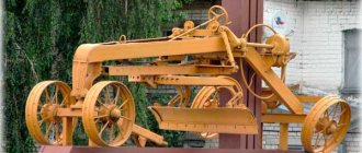
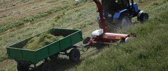
In a trailed grader, a traction frame with a rotating circular mechanism and a blade are mounted between the front axle and the rear axle on the main frame. The wheel axle is connected to the tractor's towing bracket by a drawbar. The operator controls the installation of the blade using a steering mechanical drive or levers of the spool device of the hydraulic system.
Figure 1 Trailed grader with driver steering control
A semi-trailer grader usually does not have a front axle and the length of the machine is shorter. The main frame is connected to the tractor hitch via a ball joint assembly. The hydraulic drive of the blade installation is controlled by the operator of the traction tractor.
Both units are towed by a tracked or wheeled tractor. The cost of towed devices is significantly lower than their self-propelled counterparts.
Figure 2 Tractor T-150 and semi-trailer hydraulic grader SD-105A
The trailed grader is structurally complex and ineffective in use. The disadvantage is that, in addition to the tractor driver, the operator of the unit controls it. Similar machines with a steering mechanism for mounting the blade are no longer produced and have been replaced by more productive semi-trailer graders with hydraulic drive of the executive equipment, controlled by the tractor operator:
- SD-105A for traction tracked and wheeled vehicles DT-75, T-150K, K-701;
- DZ-168 for the T-150K tractor.
1950s
Motor grader D-395 . At the end of the 50s, the Chelyabinsk plant created a heavy grader D-395 weighing 17.5 tons. In those years, the machine was an example of technical progress - all 6 wheels of the machine were driven, and the power of the 2-D6 engine was 150 hp. Tire pressure was regulated from the cab, and the steering was equipped with a pneumatic booster. For all these and other innovations, the D-395 received a gold medal at the international exhibition in Brussels in 1958. True, in the early 60s, production had to be stopped due to design defects identified in the work.
The model was improved, and in 1965 the D-395A modification was released with power steering and a new transmission. Even earlier, a “younger brother” appeared - the D-394 with driven rear axles and the ability to turn the wheels only in a horizontal position. After 6 years, the model underwent further changes - all the mechanics of controlling the working parts of the grader were replaced with hydraulics. In this form, the grader entered service with the index D-395B.
Motor grader D-426 . The first grader model developed at the Oryol plant and released in 1957. It differed from all previously produced by other Soviet manufacturers in having two axles (instead of three) and fully hydraulic control. The 9-ton vehicle was driven by a 110-horsepower YaAZ-204D diesel engine. True, the new product did not gain distribution due to massive defects identified and was discontinued from production.
Motor grader D-473 . This model can rightfully be called the first transformer in special equipment produced by the Oryol plant. In fact, it was a 20-ton tractor with a frame attached to the front with equipment for working with a blade. The designer was equipped with a hydraulic drive mechanism, hydraulic transmission and a D-12A diesel engine with a power of 300 hp. But the development did not receive recognition, and after several dozen copies were released, production stopped.
Motor grader D-547 . At the end of the 1950s, the Oryol plant finished testing its new development with the index D-547. It was a heavy grader, equipped with a 150-horsepower U-2D6 diesel engine and weighed 12 tons. Unfortunately, it also turned out to be unclaimed.
Technical parameters of non-self-propelled graders
| Model designation | DZ | SD | ||
| 6a | 1 | 168 | 105A | |
| Execution | trailed type | semi-trailer type | ||
| Traction force on the tractor hitch, tf | 3-4 | 10-12 | 10 | 10 |
| Control type | Mechanics | hydraulics | ||
| Dimensions of grader dump device, m | ||||
| along the length (without extender) | 3,0 | 3,7 | 3,74 | 3,66 |
| in height | 0,40 | 0,5 | 0,62 | 0,64 |
| Removal of the blade to the side beyond the clearance, m | 0,45 | 0,54 | 0,8 | 0,7 |
| Clearance to surface (clearance), m | 0,3 | 0,35 | 0,3 | |
| Immersion of the blade into the ground, m | 0,3 | 0,25 | 0,3 | |
| Mounting angles of the dump device, degrees | ||||
| When cutting soil | 29…57 | 29…61 | 30…70 | 28…60 |
| When gripping a soil mass with a turn at an angle | 35…90 | 35…90 | 360 | 260 |
| Tilt of the knife when cutting a slope | 60 | 65 | — | 70 |
| Weight of the grader ready for work, t | 2,8 | 4,0 | 3,35 | 3,37 |
| Dimensions by dimensions, m | ||||
| by lenght | 6,69 | 7,84 | 6,03 | 6,2 |
| in width | 2,44 | 2,86 | 2,4 | 2,5 |
| in height | 2,78 | 2,78 | 2,4 | 2,2 |
Soviet graders from the 1980s
According to the GOST in force in the 1980s, motor graders were divided into three groups: light (weight 9-10 tons), medium (weight 10-13 tons) and heavy (weight 13-19 tons). The main Soviet light-class motor grader was the DZ-99 produced by the Bryansk Road Machinery Plant (now -). Early modifications of this model, put into production back in 1969, bore the index D-710. At the turn of the 1960s - 1970s, the indexing system for road equipment changed, one letter “D” was replaced by two, of which the second began to indicate the purpose of the road machine: preparatory, earthmoving, compaction, construction or operational. Graders are classified as earth-moving machines and, accordingly, began to carry the indices DZ-...
The DZ-99 motor graders, depending on the modification, were equipped with AM-41G (90 hp) or D60K-S1 (60 hp) diesel engines; the vehicle weight was 9.5 tons. This model was discontinued back in the 1980s, but a lot of them were produced and they are still found among road workers, especially since some of the cars underwent major repairs.
In 1984, the Bryansk plant launched the production of a medium-class motor grader DZ-143, weighing 13 tons, equipped with an A-01MS engine with a power of 130 hp.
DZ-143 was equipped with a ripper-pick, located at the rear of the machine. The photo clearly shows the ripper frame and the hydraulic cylinder that serves to lower it, but all three ripper teeth have been removed.
The last model of motor grader put into production at the Bryansk Road Machinery Plant in Soviet times was the DZ-180, which was a development of the DZ-143.
The main characteristics of the vehicle remained the same as its predecessor: engine power - 130 hp, weight - 13 tons. The photo shows a modification of the DZ-180A. Nowadays, motor graders continue to be the main product of Bryansk Arsenal; a whole line of machines is produced under the GS index.
Another large manufacturer of motor graders in the USSR was the Oryol Road Machinery Plant. In 1964, the very successful middle-class model D-557 began to be produced there, later renamed DZ-31, in accordance with the new indexing system. The weight of the DZ-31 was 13 tons, and its AM-01MD engine had a maximum power of 130 hp.
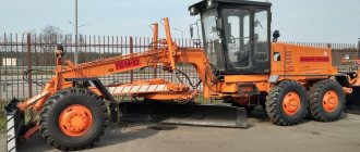
Soviet auto grader of the 80s of the last century
Now these cars are extremely rare, and those that survived into the 2000s were often overgrown with alterations. In particular, during operation, this Omsk specimen was equipped with a cabin from the DZ-99.
During the modernization of the DZ-31 in the 1980s, a new model was developed in Orel - the DZ-122, modern modifications of which the plant still produces today.
Different modifications of the DZ-122 are equipped with a variety of engines; the classic version had an A-01MS engine with a power of 130 hp, and the grader weighed the same standard 13 tons. Modern versions of the machine are equipped with engines (including imported ones) with a power of up to 180 hp.
The only heavy-duty motor grader produced in the USSR in the 1970s and 1980s was the DZ-98. This impressive car has been produced by the Chelyabinsk Road Car Plant named after Kolyushchenko since 1972. In 1977, the DZ-98 was awarded the Quality Mark; in addition, the car received a gold medal from the USSR Exhibition of Economic Achievements.
The weight of the car is about 19 tons, the engine power is 250 hp, almost twice as much as that of its “colleagues” from the middle class. The motor grader has an all-wheel drive transmission; the front wheel drive is clearly visible in the photo. A ripper is installed in the front part, which can be used to loosen frozen or rocky soil and break up old asphalt.
continues production of this model, modern modifications are equipped with YaMZ-238NDZ engines or the more powerful Cummins M-11C265. Also, upon request, the factory can supply the motor grader with air conditioning and a cabin with an increased level of protection.
0