MAZ fuse box
The MAZ fuse box is a device that houses safety elements designed to prevent damage to electrical devices and equipment.
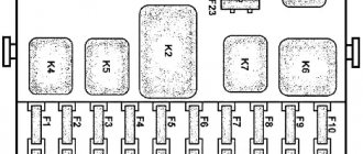
The MAZ safety panel includes three modules:
- In the first block, in accordance with the layout, there are fuses for 30 and 60 amperes. These elements are designed to protect generator sets and batteries from overvoltage and short circuits. The main component of the 60 amp relay box powers almost all electrical loads, except for the light alarm, since it is connected directly to the battery.
- The second fuse box contains 21 6 amp devices.
- The third module contains 9 8-amp components and one 16-amp component.
On the module itself there is a protective cover, on which information with labels is applied. The latter explain the purpose of safety devices and relays and indicate the resistance rating of the parts. All elements differ in appearance and location, but they are all designed to ensure the correct operation of the vehicle's electrical circuit. If voltage surges occur in the network, the fuse is the first to break, protecting electrical equipment from failure.
Only these components can operate without fuses:
- starter relay;
- main light switch;
- ground disconnect winding;
- mechanism for deactivating devices and automatic starting.
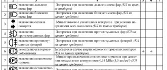
Marking and description of safety elements located in the second module:
- 127 – device responsible for protecting the speedometer, speed control mechanism;
- 57 – brake lights;
- 90 – windshield washing and cleaning systems;
- 120 – wheel and axle locking mechanism, reversing lights and optical hitch lighting devices;
- 162 – heating system for side rear-view mirrors;
- P61 – fuse responsible for the operation of the instrument lighting system;
- 55 – anti-fog optics protection device;
- 52 – side optics installed on the right and left of the car;
- 56 – left and right low-beam headlights;
- 53 – safety element for additional high-beam headlights;
- 54 (marked K and Z) – high beam headlights installed on the right and left, respectively;
- 78 – vehicle turning lights;
- 79 – light signaling of the vehicle;
- 80 – heating system fan;
- 31 – light indicators of the instrument cluster and control indicator;
- 50 – rear fog optics.
Also in this part of the module there are 11 relays:
- 1 – steering horn and sound signals;
- 2 – reversing lights;
- 3 – blocking of grounding disconnection;
- 4 – brake light lamps;
- 5 – relay responsible for the operation of the on-board control system;
- 6 – low beam optics;
- 7 – high beam blocking system;
- 8 – side lights;
- 9 – high beam;
- 10 and 11 – electric torch elements.
The third part of the module is marked PR112 and includes ten elements:
- valve – safety device for the cooling system fan clutch;
- 59 – element of the cabin lighting system;
- 131 – fuse responsible for the refrigerator, pneumatic signal, socket of an emergency light bulb;
- 133 – air dryer;
- 161 – safety component of the engine stop valve;
- 171 – timer and car radio fuses;
- 172 – element responsible for the operation of the body lighting system;
- 179 – malfunction of the fuel heating system;
- One slot in the module is reserved.
Kotelniki, st. Novoryazanskoe highway building 6, building 4, floor 2, office 18
Working hours: from 9:00 to 21:00 seven days a week
Source
Not available:
| № | Part code | Name | Quantity per model, pcs. | |
| 1 | 64221-3711047 | A loop | 1 | Not available |
| 2 | 64221-3722023 | Bracket for fuse and relay blocks | 1 | Not available |
| 3 | 64221-3747015 | Relay bracket | 1 | Not available |
| 4 | 64221-3903066 | Fuse box plate | 1 | Not available |
| 5 | Pr112-3722000 | Fuse box | 1 | Not available |
| 7 | 47KTU16-526-358-74 | Socket | 1 | Not available |
| 8 | 64229-3724095 | Jumper | 4 | Not available |
| 10 | RS493-3803010 | Parking brake lamp relay | 1 | Not available |
| 11 | 12-3741000 | Additional resistance | 1 | Not available |
| 12 | 64221-3722020 | Bracket for fuse and relay blocks | 2 | Not available |
| 13 | 535A-3724015 | Sleeve | 1 | Not available |
| 14 | 220082 | Screw M5-6ghx20 | 2 | Not available |
| 15 | 220104 | Screw M6-6gx14 | 4 | Not available |
| 16 | 220107 | Screw M6-6gx20 | 2 | Not available |
| 17 | 221512 | Screw M3-6ghx28 | 2 | Not available |
| 18 | 250458 | Nut M3-6N | 2 | Not available |
| 19 | 250464 | Nut M5-6N | 2 | Not available |
| 20 | 250508 | Nut M6-6N | 1 | Not available |
| 21 | 252004 | Washer 6 | 2 | Not available |
| 22 | 252130 | Washer 3T | 2 | Not available |
| 23 | 252133 | Washer 5T | 2 | Not available |
| 24 | 252154 | Washer 6L | 1 | Not available |
Maz 5440 / 6430 euro - fuses and relays
Maz 5440 and Maz 6430 are the general designations for two series of truck tractors of the Minsk Automobile Plant produced from 1997 to the present with various modifications and changes (643008, 6430A8, 643005, 6430A5, 6430A4, 631208, 6312A8, 544009, 5440A9 , 544008, 5440A8, 544005, etc.) and generations (Euro 3 4 5 6). In this article you will find a description of the most popular fuse and relay blocks Maz 5440 and Maz 6430 with diagrams and their locations.
A few words about the replacement
However, we will tell you an approximate algorithm for replacing a part using the BSK 4 scheme.
Typically, part failure occurs as follows:
- Pieces of multilayer boards and tracks burn out;
- There is a short circuit in the conductive harnesses or wiring;
- Block BSK 4 fails.
If you want to try to restore the part, do the following.
- Having previously studied the diagram of the BSK 4 MAZ block, remove the part. Then look closely at the damage.
If you find burnt tracks, carefully trim their channels so that they do not touch each other/
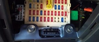
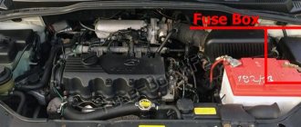
Block in the cabin
The main fuse and relay box is located in the passenger compartment, in the middle of the dashboard, on the passenger side and is closed with a protective cover.
The design of the block and the purpose of the elements in them depend on the year of manufacture and the level of equipment of the MAZ. The current designation for your vehicle will be printed on the back of the protective cover. Check the purpose, and in case of difficulty, contact your dealer.
Option 1
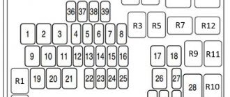
Description of fuses
p, blockquote 8,0,0,0,0 —>
- 16A refrigerator
- 16A (+) from the lock for ABS brakes
- 16A air dryer, heaters
- 16A (+) from the generator for ABS brakes
- 16A from generator for engine electronics
- 8A turns
- 8A lights
- 8A tractor brake signals
- 8A (+) with brake signal relay
- 8A reverse light
- 8A trailer brake lights
- 8A alarm
- 8A heater control unit
- 8A thermostat timer, radio
- 8A standard heater fan
- 8A independent heater heaters
- 8A high beam right headlight
- 8A high beam left headlight
- 8A low beam right headlight
- 8A low beam left headlight
- 8A size reserve
- 8A heated mirrors, power windows
- 8A fan clutch
- 8A electrical signals
- 8A voltage regulator, engine stop
- 8A engine stop valve
- 8A switches
- 8A wiper
- 8A power supply for other indicator lamps
- 8A power supply for emergency warning lamps
- 8A power supply for devices
- —
- 8A tachograph
- 6A cabin lamps
- 6A rear fog lights
- 8A additional high beam headlights
- 8A front fog lights
- 8A right side trailer
- 8A left side of trailer
- 8A instrument lighting
- 8A right side of the tractor
- 8A left side of the tractor
Option 2
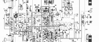
Photo - diagram
Designation
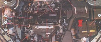
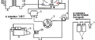
Location of the main elements of the engine ESU
1–starter control relay (intermediate); 2–battery shutdown relay; 3, 4 – fuel heating relay; 5, 6 – fuse block of engine ESU and ODI; 7–engine ESU diagnostic button; 8-diagnostic connector ISO9141; FU601 – 10A fuse for engine ESU; FU602 – 15A fuse for engine ESU; FU603 – 25A fuse for engine ESU; FU604, FU605 – fuses 5A BDI
Option 3
Description of fuses
p, blockquote 20,0,0,0,0 —>
- sound electric signal
- windshield wiper and washer
- sound pneumatic signal, voltmeter, control indicators of the hand brake relay
- alarm
- direction indicators
- road train sign and heated mirrors
- front fog lights
- rear fog lights
- reversing light
- reserve
- power supply after ignition switch
- power supply at terminal 17
- differential valves and hitch light
- tachograph power supply
- power supply for signs
- control indicators
- control indicators
- backlight
- left side low beam
- starboard low beam
- left side high beam
- daytime running light
- side lights of the left side of the trailer/semi-trailer
- marker lights on the right side of a trailer/semi-trailer
- starboard high beam
- side lights of the left side of the tractor
- air dryer pneumatic system
- side lights of the right side of the tractor
- tractor brake light
- trailer/semi-trailer brake light
- electric flare device
- reserve
- heater fan
- additional socket
- acoustic system
- interior lighting
- electronic control systems
Of course, these are not all the options for blocks and their purposes that were used in MAZs. But only the most common ones.
p, blockquote 22,0,0,0,0 —> p, blockquote 23,0,0,0,1 —>
If you have additions to this material, write them in the comments.
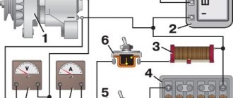
How to connect a MAZ generator
The proper operation of on-board network devices largely depends on the correct connection of the control unit. If MAZs of the famous 500th series could operate using only one battery, then this is impossible on modern cars. The presence of a large number of electronic devices and gadgets has increased the power consumption of the network and requires an additional power source.
The connection diagram for the MAZ generator depends on its type. However, in all cases, the inductor must be powered and the load must be connected, which is the on-board network and battery. The connection terminals are located on the back cover and are designated by the letters “W” and “+D” for the field winding and “+” for the load (ignition switch).
The output of one of the phases of the PG is connected to the tachometer. Terminal “B” is connected to the generator blocking relay and the battery charge indicator lamp. The connection circuit is simple, but requires attention when performing work.
Failure of BSK-4 due to short circuit.
Another team is finishing the restoration of BSK-4 on the car itself in Solnechnogorsk, which was in trouble after washing the car that week. Restoring BSK-4 did not help. The unit received too much damage in the short time it was smoking in the cabin. The owner had to buy a new one. We installed, connected, and found the cause of the short circuit. As always, however, in the side lights on one side of the body. Belarusian BSKs are so crudely made that their creations do not stand up to any criticism when washing a car.
Source
Block diagram of the on-board system UBKA (BSK-4)
The UBKA (BSK-4) scheme is unique in its kind. Repairing and re-soldering a part due to the detection of any malfunctions is extremely difficult. Troubleshooting yourself is highly undesirable. Repair of the mounting block can only be carried out with the help of professional craftsmen. After all, incorrect operation of a part can lead to a short circuit in the electronics in your car. Therefore, in this case, it is safer to purchase a new BSK-4 unit. In order to detect faults in the UBKA unit (BSK-4) in time for the purpose of replacing it, it is necessary to carefully monitor the condition of the fuses, as well as the normal operation of the electrical systems in the MAZ vehicle.