History of the creation of ZMZ 406
The Zavolzhsky plant engine number 406 begins its history from the very end of the eighties. At the engine design stage, it was clear that the power unit would become a promising invention. This conclusion could be safely made taking into account the advanced trends in engine building that were embedded in its creation.
The latest achievements in engine building at that time were considered:
- electronic control of processes occurring in the power unit;
- sixteen valve cylinder head;
- installation of an injection system to power the internal combustion engine;
- the use of a cast iron block implied a long service life of the internal combustion engine, taking into account two repair borings for cylinders and a crankshaft of three sizes.
The first prototype was assembled in 1989, then the Zavolzhsky Motor-Building Plant and the Gorky Automobile Plant were in close cooperation. GAZ intended to get a new engine for the promising new Volga model - Gas 3105.
On the eve of 1991, the engine underwent every conceivable and unimaginable test. It was completely ready for mass production. But it was 1991, the collapse of the country and the collapse of the economy could no longer be prevented. With great difficulties, in difficult economic conditions in 1992, the Gorky Plant sent an experimental batch of engines to the OPP.
A year later, the assembly of motors in small batches began. And already in 1994, the 406 engine received registration for the Gas 3102 Volga. And a year later this engine was installed on GAZELLES. It should be noted that the engines of those years had carburetor and not injection power. Also in 1995, the Zavolzhsky plant produced several prototypes of the ZMZ 406 with an injection type of power supply.
By the end of 1996, the assembly of ZMZ 406 was transferred to the main conveyor. In 1997, full-scale serial production of the new internal combustion engine began. In parallel with the work of the main conveyor, engineers and designers work. They are looking at various engine upgrades. As a result of their work, modernized power units ZMZ 409 AND ZMZ 405 will soon appear.
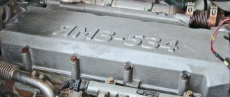
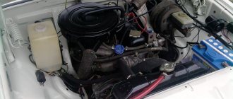
ZMZ 402
It’s strange that this internal combustion engine ended up on a new car - you can’t equip cars with the same engine for so many years. For the first time, this engine began to be serially installed on the Volga transition model GAZ 24 M in 1985, and since then has not undergone virtually any changes. However, it came to GAZ 31105 from the factory in 2004 and 2005.
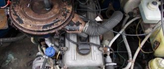
Replacing the oil filter in the ZMZ-402 engine
Of all the engines installed on the GAZ 31105, the 402nd engine is the least powerful and low-speed. It has its own characteristic malfunctions, which are most common:
- Oil leak from the rear main bearing (from the stuffing box);
- Broken hex drive of the oil pump;
- Fallout of valve seats in the cylinder head.
Increased oil loss through the piston rings;
If many shortcomings could somehow be tolerated, then the loss of a valve seat became a real disaster for the car owner.
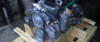
Main features of the ZMZ 406 internal combustion engine
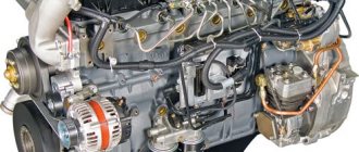
The power unit of the 406 model, produced by the Zavolzhsky plant, which produces automobile engines, can safely be called a pioneer of the domestic engine industry. It was on the ZMZ 406 engine that some of the advanced technologies of world engineering leaders were used for the first time. But let's talk about all this in order.
Cylinder block
The internal combustion engine cylinder block is cast from highly durable cast iron. Because of this, the total mass of the product has increased, but there is no need to use replaceable liners (cylinders). Also in favor of cast iron as a product material is the special rigidity and strength of the structure.
DOHC system
For the first time in the domestic engine industry, the DOHC system is used in the engine gas distribution system. Where there are two overhead shafts. One shaft has eight valves and is responsible for the intake of the combustible mixture. The second shaft with eight valves is responsible for the exhaust gases.
Cylinder head
As a result, each individual cylinder has two valves for exhaust and two for intake. ZMZ 406 was the first domestic power unit on which a sixteen-valve cylinder head was installed. The number of valves doubled compared to previous engines increases the possibility of purging the combustion chamber during the release of exhaust gases. And while filling the cylinders with the combustible mixture, the filling coefficient is multiplied.
The cylinder head valves on this engine are equipped with hydraulic pushers. This mechanism is used for the first time in the domestic engine industry. Hydraulic pushers automatically adjust the thermal clearances in the valves, thereby eliminating periodic, manual adjustment of the valves.
Timing drive
The timing drive here is chain driven. The chain resource according to manufacturers' requests is 200 thousand km. There are known cases of chain service over a period of 500 thousand km. But there have been cases when the timing chain broke in less than 100 thousand km. Therefore, it is necessary to inspect the timing chain for mechanical wear and damage after a mileage of 70 thousand km. However, if the chain breaks there will be no major damage, the 406 valve motor will not bend. The timing drive is two-stage; the first fuel mixture distribution shaft is driven from the crankshaft sprocket, and from it the shaft responsible for the exhaust gases is driven.
Also, it was on the ZMZ 406 that a hydraulic chain tensioner was used for the first time in the Russian engine industry. Its functions include maintaining optimal voltage for the timing drive. Subsequently, this innovation was adopted on many power units.
Other Features
A special feature of this engine is its short piston stroke of 86 mm, compared to a cylinder diameter of 92 mm. This design contributed to an increase in the compression ratio. The compression ratio of ZMZ 406 is 9.3:1. This approach helps to increase the efficiency of the power unit.
Also, an innovation on the ZAZ 406 engine is the use of an injection power system and the use of an electronic system that controls fuel injection and a contactless ignition system
Service
Maintenance of ZMZ 406 engines of all modifications is carried out the same way. TO-0 is done after a mileage of 2500 km. Each subsequent maintenance must be carried out every 15,000 km when operating on gasoline and 12,000 km for gas.
During scheduled maintenance, lubricant and filters are replaced. Every 65-70 thousand km it is necessary to change the timing belt repair kit. The ZMZ 4062 is equipped with a chain and shoe, as well as drive and drive sprockets.
Every second maintenance requires checking systems such as the valve mechanism, the condition of the electronic powertrain control unit, and the functionality of sensors. The valve mechanism is adjusted after 50,000 km, or earlier if necessary.
Often, by 70,000, hydraulic compensators fail, which need to be replaced all together, since it is unknown when the functional ones will fail. The valve cover gasket is replaced every 40,000 km or when a leak develops under it.
It is recommended to fill the engine with semi-synthetic oil marked 5W-30, 5W-40, 10W-30, 10W-40, 15W-40, 20W-40. To change the oil you will need 5.4 liters, which are poured into the power unit. As practice shows, most motorists perform engine maintenance themselves.
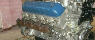
Modifications of the ZMZ 406 engine
In general, there is no power unit under the exact marking ZMZ 406. This is a generalized name for several engines that are very similar to each other.
Here are their main differences:
- ZMZ 4061 10 is a 16-valve 2.3-liter engine with a compression ratio of 8:1. The power system has a carburetor. Such a low compression ratio allows the use of gasoline with an octane number of AI 76 as fuel.
- ZMZ 4062 10 is the same 16-valve engine with the same volume. Only the compression ratio of this engine is 9.3:1. The power supply system of this internal combustion engine is an injector and electronic fuel injection control.
- ZMZ 4063 10 this engine differs from the previous one in that it has a carburetor in the power system. The compression ratio of 9.3:1 guarantees smooth operation of the internal combustion engine on AI 93 gasoline.
Carburetor ICE models differ significantly in power from injection foreign analogues. For example, internal combustion engines produced in Europe with a volume of 2.3 liters develop power of up to 150 hp, power and torque of more than 200 Nm. The power of domestic carburetor ZMZ 406 with the same volume is only 100 liters. It was possible to achieve the best technical indicators by creating the injection model ZMZ 406. Its technical characteristics are close to European indicators.
Specifications and description
Structurally simple and easy to maintain, the 406 engine was an excellent power unit. Increased power and reduced fuel consumption allowed the power unit to blend harmoniously into the cars. In addition to the vehicles of the Gorky Automobile Plant, the 406 engine was mounted on the UAZ.
The first generation of the 406 engine had a carburetor injection system, but with the widespread arrival of the injector, it was decided to improve the engine and adapt it to distributor injection.
So, let's look at what technical characteristics the 406 engine has:
Also, the Volga region produced a forced engine - ZMZ 40620D. On many vehicles, the letter D means that the power unit is classified as a diesel engine, but in the case of our factories the situation is different - it is a designation of power.
Let's look at the technical characteristics of the ZMZ 40620D engine:
As you can see, the only difference is the amount of horsepower. Other indicators do not change.
All cars were equipped with a 5-speed manual transmission. The design of the ZMZ 406 engine is simple. Unlike its predecessor, the 402, this power unit featured two camshafts and 16 valves. The ignition system has also been adapted. The engine life has increased to 250,000 km, instead of 150,000 km.
Technical data ZMZ 406
- Manufacturer ZMZ 406 Zavolzhsky plant for the production of automobile engines. Release period from 1997 to 2008.
- A four-stroke gasoline engine with an in-line arrangement of four cylinders.
- The material used to make the BC is a particularly durable cast iron alloy.
- DOHC gas distribution system with two timing shafts and 16 valves. The timing chain drive has two stages, equipped with a hydraulic tensioner.
- The ZMZ 4062 model has an injection power system. The ZMZ 4061 and ZMZ 4063 are equipped with a carburetor system.
- The piston stroke of this internal combustion engine is 86 mm, the diameter of its cylinders is 92 mm.
- The 4061 model has a compression ratio of 8:1, while the 4062 and 4063 models have a compression ratio of 9.3:1.
- The exact volume of the internal combustion engine is 2286 cubic centimeters.
- The fuel used is AI 76, AI 92 depending on the compression ratio.
- European compliance standards for toxic emissions for the injection version of ZMZ 4062 Euro 2 and Euro 3.
- The weight of the power unit is 185 and 187 kilograms.
Power
ZMZ 4061 at 4500 rpm, equal to 100 l., forces, ZMZ 4063 at 4500 rpm, equal to 110 l., forces, ZMZ 4062 at 5200 rpm, equal to 145 l., forces. Torque 177, 186, 201 Nm at 3500 and 4000 rpm, for the corresponding ZMZ models.
Fuel consumption
Fuel consumption when driving in city mode is 13.5 liters per 100 km, mileage, on the highway 8.8 liters, total fuel consumption is 11 liters per 100 km, mileage. The data corresponds to the consumption of Gas 31105 with manual transmission.
How many liters of oil and what kind to fill?
The permissible consumption of motor lubricant is 0.1 liter per 1000 km, mileage. Types of oil used: 15W40, 10W40, 20W40, 10W30, 5W40, 5W30. Engine oil volume is 6 liters. To replace, take 5.4 liters. Replace engine lubricant every 7 thousand km.
Engine life
According to manufacturers, the operating life of the engine is 150 thousand km. In reality, with careful driving and proper timely maintenance, this figure can be twice as high.
Service
Maintenance of ZMZ 406 engines of all modifications is carried out the same way. TO-0 is done after a mileage of 2500 km. Each subsequent maintenance must be carried out every 15,000 km when operating on gasoline and 12,000 km for gas.
During scheduled maintenance, lubricant and filters are replaced. Every 65-70 thousand km it is necessary to change the timing belt repair kit. The ZMZ 4062 is equipped with a chain and shoe, as well as drive and drive sprockets.
Every second maintenance requires checking systems such as the valve mechanism, the condition of the electronic powertrain control unit, and the functionality of sensors. The valve mechanism is adjusted after 50,000 km, or earlier if necessary.
Often, by 70,000, hydraulic compensators fail, which need to be replaced all together, since it is unknown when the functional ones will fail. The valve cover gasket is replaced every 40,000 km or when a leak develops under it.
It is recommended to fill the engine with semi-synthetic oil marked 5W-30, 5W-40, 10W-30, 10W-40, 15W-40, 20W-40. To change the oil you will need 5.4 liters, which are poured into the power unit. As practice shows, most motorists perform engine maintenance themselves.
BC design
The cylinder head is cast from a particularly strong cast iron alloy. Jacket channels pass between the cylinders to circulate coolant. The cylinders are drilled into the BC. In the lower, inner part of the BC there are five supports necessary for installing the crankshaft plain bearings. The bearing caps are made by forging cast iron. They are bored together with the supports. Therefore, the covers cannot be swapped.
Numbers are stamped on the first, second, fourth and fifth covers for correct installation. The third cover is additionally processed at the ends. End machining is needed to install the thrust bearing half washer.
The oil seal holder and crankshaft cuffs, as well as the timing chain cover, are bolted to the ends of the BC. The oil sump is bolted to the bottom of the cylinder block.
Description of cylinder head design
On the BC, from above, through the gasket, the BC head is bolted. The head is made of aluminum alloy. It houses the exhaust and intake valves. Each individual cylinder has four valves, two exhaust valves and two intake valves. The intake valves are on the right side of the engine, and the exhaust valves are on the left. The valves are driven from two camshafts by hydraulic pushers.
The presence of hydraulic pushers simplifies the maintenance of the car engine. Since the need for periodic adjustment of thermal clearances in the valves disappears. On the surface of the hydraulic pusher there are holes and grooves necessary for the passage of motor lubricant into the pusher.
In the cylinder head, guide bushings and valve seats are inserted into the valve holes. At the bottom of the cylinder head there are combustion chambers, at the top there are supports for the shafts of the gas distribution mechanism. The supports have covers made of aluminum. The first cover along the vehicle, common to the first two supports of both shafts. It contains persistent plastic flanges. They are inserted into the grooves on the shaft journals. Other support covers are processed together with the cylinder head supports. Therefore, they cannot be swapped. All covers, with the exception of the first double, are numbered. The top of the cylinder head is covered with an aluminum alloy cover.
Description of the design of ShPG ZMZ 406
The pistons of the 406 engine of the Zavolzhsky plant are made of a special aluminum alloy. All pistons have indentations at the bottom. These recesses prevent the pistons from colliding with the valves if the timing chain breaks. When assembling the engine after repair, for the correct installation of the pistons, there is an inscription “Front” on their wall. This inscription is located above the boss of each piston. The piston must be positioned so that this inscription is in front of the movement of the car.
Each piston is equipped with two compression rings and one oil scraper ring. Compression rings are made of cast iron. The surface of the upper ring, the one that interacts with the cylinder walls, is coated with a thin layer of chromium. This speeds up the ring grinding. The surface of the compression ring located below is covered with a thin layer of tin. The inner surface of this ring has a groove. This ring must be installed on the piston, with the flow upward, towards the bottom of the piston.
The oil scraper ring has three elements: two thin steel disks and an expander. The piston is connected to the connecting rod using a piston pin. Floating connection design. In other words, the finger moves freely both in the piston and in the connecting rod head. The pin is held against lateral displacement by two spring retaining rings installed in the piston bosses.
The connecting rods are made of forged steel and have an I-section rod. In the upper head of the connecting rod there is a pressed bronze bushing. The lower head on the connecting rod has a cover screwed to the connecting rod with two bolts. The covers are processed together with the connecting rods, so they cannot be swapped. The caps and connecting rods are numbered so that they are not confused during assembly. The bolt nuts securing the connecting rod cover are equipped with self-locking threads and do not require additional locking.
The piston bottoms have forced cooling. To do this, holes are drilled in the connecting rod rod and its upper head. Through them, under pressure, motor lubricant reaches the bottom of the piston, thereby cooling it. The weight of the piston and connecting rod assembly must be the same in all cylinders. The permissible difference is 10 grams. The lower head of the connecting rod holds the connecting rod thin-walled plain bearings.
Replacing wiring
Wiring for Gazelle 406 engine with pinout of ECU connector terminals
It is certainly not impractical to change the entire electrical wiring of the Gazelle when replacing the engine from 402 to 406.
The fact is that on newer versions of Gazelles, the connection diagram of certain devices also changed:
- Gazelle 406 wiring is integrated into the standard electrical system in the engine compartment;
- electronic components and control devices are connected using terminals;
- The voltage and correct connection are checked using testers.
After assembling the wiring into a single whole, its functionality is checked. Subsequently, the operation of the power unit is adjusted.
Conclusions: Replacing the power unit inevitably affects the change in the standard electrical wiring of the car
That is why it is important to have a visual aid at hand when carrying out such an operation, and the Gazelle’s factory wiring diagram will allow you to avoid mistakes
Description of the crankshaft design
The crankshaft material is high-strength cast iron. There are eight counterweights on the crankshaft. It is kept from moving along the axis by thrust washers installed on the journal, which is located among the crankshaft. A flywheel is attached to the rear end of the latter. It is needed to accumulate and release energy when the need arises. A bearing and bushing for the gearbox input shaft are inserted into the hole located in the middle of the flywheel. There are oil lines inside the crankshaft to supply lubricant to the plain bearings, then to the connecting rod and through the connecting rod line to its upper head.
Further modernization
Plans to increase sales volumes were not destined to come true. There are several reasons for this:
- Quite high costs of operating a GAZ car with low functionality;
- Obsolescence of the design in terms of passive safety;
- Poor body corrosion resistance;
- Lack of comfort features.
The wiring diagram of the GAZ 31105 with the Daimler Chrysler power unit complied with European standards.
All this forced the automaker to engage in deep restyling, as a result of which the GAZ 31105 model appeared in 2004.
Among its features it should be noted:
- DOНC power unit with a volume of 2.4 liters from Daimler Chrysler;
- Electronic throttle pedal;
- A new instrument panel, redesigned to meet safety requirements;
- A control panel for power windows and exterior mirror adjustment located on the driver's door;
- New headlights and taillights;
- Air conditioner.
All this led to the fact that the electrical wiring diagram of the GAZ 31105 changed radically. Although the car became more similar in functionality to its foreign counterparts, it nevertheless could not compete with them.
Original photo of electrical equipment of GAZ 31105 with Daimler Chrysler engine
Features of the ZMZ 406 cooling system
The cooling system of the engine in question is made in a traditional style. The cooling liquid is pumped by a water pump through the BC, BC head, and radiator. The system uses a flat poly V-belt. Such a belt eliminated the possibility of unexpected breakage.
The system includes a thermostat. It directs the flow of coolant in a large or small circle, depending on the engine warm-up temperature. Also, if necessary, pump 406 supplies cooling liquid to the heater, thereby providing warmth and comfort in the car interior. The system includes a temperature sensor that constantly indicates the temperature of the coolant. It allows the driver to constantly monitor the temperature of the internal combustion engine.
Engine control system ZMZ 4062.10
Engine control system ZMZ – 4062.10
On GAZ-3110 Volga cars with a ZMZ-4062.10 engine, a distributed fuel injection system is installed (fuel is injected into each cylinder with a separate nozzle). The composition of the ZMZ-4062.10 engine control system is given in table. 5.1, and in Fig. Figure 5.1 shows its functional diagram.
Signals from the crankshaft position sensors, camshaft position (phase), air and coolant temperature, detonation, air flow and throttle position sensors enter the control unit, which processes them and generates control signals to the ignition system, injectors, secondary air regulator and fuel pump , providing an engine operating mode that is rational for current conditions and reducing exhaust gas toxicity. In addition, the control unit performs the functions of monitoring and self-diagnosis of the system, and also controls the operation of the engine in reserve mode (in the event of failure of individual elements of the system).
Functional diagram of the ZMZ-4062.10 engine control system: DPKV
– crankshaft position sensor;
DPRV
– camshaft position sensor;
DT
– coolant temperature sensor;
DD
– knock sensor;
UHF
– mass air flow sensor;
TPS
– throttle position sensor;
DTV
– air temperature sensor;
Ф 1 …Ф 4
– nozzles;
EBN
– electric fuel pump;
RDV
– secondary air regulator;
SZ
– ignition system;
St
- candles
The main structural elements of the system's electrical equipment are sensors, a control unit, an electric fuel pump with a switch-on relay, an additional air regulator, injector solenoid valves and an ignition system.
Microprocessor control unit
"MIKAS 5.4" is installed under the instrument panel on the right side and is designed to solve the following functional tasks:
generating the torque and required duration of electrical pulses to control the operation of electromagnetic fuel injection injectors;
generation of electric current pulses in the primary windings of the ignition coils, taking into account the required ignition timing;
control of the operation of the secondary air regulator;
control of engine operation in standby mode (in the event of failure of individual system elements);
control and self-diagnosis of the system.
There are three types of memory in the control unit: read only memory (ROM), random access memory (RAM) and electrically rewritable non-volatile memory (EEPROM).
ROM is a non-volatile memory that contains an unchangeable and non-deletable control program corresponding to a specific type of engine.
RAM is a volatile memory that stores operational information received from sensors. To save RAM data, even a short-term decrease in the voltage of the control unit below 6 V is unacceptable.
An electrically rewritable, non-volatile memory device stores information about the features of the control unit, its manufacturer, as well as information related to the initial settings of the control system.
Electromagnetic injectors
0280150711 or 19.1132010 (Fig. 5.2) are designed for injecting a measured amount of fuel into the engine cylinders.
Electromagnetic injector:
1 – spray nozzle; 2 – sealing ring; 3 – washer; 4 – valve needle; 5 – seal; 6 – limit washer; 7 – body; 8 – insulator; 9 – electromagnet winding; 10 – plug; 11 – block; 12 – filter; 13 – tube; 14 – cover; 15 – spring; 16 – electromagnet core; 17 – spray valve body
The injectors are installed in the engine intake pipe. Fuel is supplied to the injectors through a fuel line, the pressure in which during engine operation is 2.8...3.25 kg/cm2. Structurally, the nozzle is a high-precision electromechanical device containing a housing 7, an electromagnet winding 9, an electromagnet core 16, a shut-off valve needle 4, a spray valve housing 17, a spray nozzle 1 and a filter 12.
The fuel is supplied under pressure to the shut-off valve through filter 12. In the absence of a control pulse on the electromagnet winding 9, the shut-off valve is closed, since spring 15 presses the valve needle to the conical hole of the nozzle body 17. When an electrical impulse arrives from the control unit to the electromagnet winding 9, the electromagnet core 16 is retracted and moves the shut-off valve needle 4. The hole in the body 17 of the atomizer opens and fuel under pressure enters the atomized mixture into the engine cylinder. When the electrical control pulse disappears, spring 15 returns core 16 and shut-off valve needle 4 to their original position: the fuel supply to the cylinder stops.
Crankshaft position sensor
: 1 – sensor winding; 2 – body; 3 – magnet; 4 – seal; 5 – wire; 6 – mounting bracket; 7 – magnetic wire; 8 – synchronization disk
car fuel sensor electric fuel pump
Rice. 5.4. Camshaft position sensor
The duration of the electrical pulse supplied to the winding of the injector electromagnet (and therefore the amount of fuel supplied to the engine cylinder) is determined by the control unit based on sensor signals. Using crankshaft and camshaft position sensors, the fuel supply to the engine cylinders is synchronized with the position of the pistons in the engine cylinders: fuel is supplied to the cylinders in accordance with the operating order of the engine cylinders.
Engine crankshaft position sensor 026120113
(Fig. 5.3) serves to determine the angular position of the engine crankshaft, synchronize the operation of the control unit with the engine’s operating process and determine its rotation speed.
The design and functions of the sensor are similar to the synchronization sensor of the microprocessor ignition system of the Sobol car.
The crankshaft position sensor is installed at the front of the engine on the right side and works in conjunction with a timing gear mounted on the crankshaft pulley.
Camshaft position sensor
(Fig. 5.4) serves to determine the TDC of the piston of the first cylinder during the compression stroke. The sensor is located on the left side of the cylinder head (at the fourth cylinder) and is an electronic device that operates on the Hall effect. When a metal plate mounted on the camshaft at the end of the sensor passes, a signal appears at its output, which is sent to the control unit. The control unit, processing signals from the crankshaft and camshaft position sensors, synchronizes the fuel supply to the injectors in accordance with the operating order of the engine cylinders.
If the camshaft position sensor fails, the control unit switches to standby mode, sending signals
control simultaneously for all injectors.
Mass air flow sensor
IVKSH 48728200 (Fig. 5.5) are used to determine the amount of air used to fill the cylinders during engine operation. The sensor is installed in the intake system after the air filter and contains a sensing element 2, a thermal compensation resistor 3, as well as an electronic module 14. The sensing element is a platinum thread with a diameter of 0.07...0.1 mm, wrapped inside ring 1, which in turn is installed in building 8.
When the engine is running, the air entering the engine cylinders passes through ring 1, cooling the platinum filament. The electronic module restores the filament temperature to its previous level. The more air passes through the sensor, the more the filament cools and the more power the electronic module expends to restore the temperature of the filament. The output signal of the sensor is proportional to the power expended by the electronic module, and therefore to the amount of air passing through the sensor.
Mass air flow sensor:
1 – ring; 2 – platinum thread; 3 – temperature compensation resistor; 4 – bracket for fastening the ring; 5 – electronic module housing; 6 – safety net; 7 – retaining ring; 8 – sensor housing; 9 – CO adjustment screw; 10 – cover; 11 – electrical connector block; 12 – plug; 13 – seal; 14 – electronic module
The sensor has a screw 9, with which the content of CO and CH in the exhaust gases is regulated.
Throttle position sensor
0280122001 or NRKT-8 is installed on the throttle valve assembly housing and is mechanically connected to the throttle valve axis. The sensor is a variable resistor on a ceramic substrate and consists of a housing 1, a printed circuit board with resistors Rl, R2, R3, R4 and a movable contact 3 mounted on a rotary sleeve 2 mounted on the axis of the throttle valve 8.
When changing the throttle position, the magnitude of the voltage drop across the variable resistance changes. This voltage is supplied to the control unit, which takes it into account when calculating the duration of the injector control pulses and the ignition timing.
Knock sensor: 1 – plug; 2 – insulator; 3 – body; 4 – nut; 5 – elastic washer; 6 – inertial mass; 7 – piezoelectric element; 8 – contact plate
If the sensor fails, the control unit switches to backup mode, using its memory data and mass fuel consumption data.
Knock sensor
GT305 (Fig. 5.7) is designed to detect engine knock, i.e. spontaneous ignition of the working mixture in the engine cylinders. Detonation causes severe vibration and overheating of the engine, which can lead to mechanical destruction of its parts.
The sensor is installed on the right at the rear of the engine and consists of a quartz piezo element 7, an inertial mass 6, an elastic washer 5, a contact plate 8, a plug 1, an insulator 2 and a housing 3. When the engine is running, its parts vibrate. Vibration is transmitted to the inertial mass 6 of the sensor, which acts on the piezoelectric element with the appropriate frequency and force. As a result of the piezoelectric effect, signals of a certain size and shape appear at the output of the sensor.
Knock sensor
: 1 – plug; 2 – insulator; 3 – body; 4 – nut; 5 – elastic washer; 6 – inertial mass; 7 – piezoelectric element; 8 – contact plate
When detonation occurs, the amplitude of the sensor's electrical signals increases sharply. The control unit responds to an increase in sensor signals by adjusting the ignition timing until detonation stops.
The additional air regulator РХХ-60 (Fig. 5.8) serves to maintain a given crankshaft speed at idle, during start-up, warm-up, during coasting and with changing load from auxiliary equipment.
The regulator is a valve that regulates the flow of air into the intake system, bypassing the throttle valve. It is installed on the intake pipe, connected by tubes to the intake pipe before and after the throttle valve and consists of a two-winding electric motor (a fixed armature 9 with a winding 5 and a moving magnet 7), a rotary cup 6, a damper 16, a housing 8 with two pipes (input 15 and weekends 20). When 5 electrical pulses arrive from the control unit to the armature windings, an electromagnetic field arises, which, interacting with magnet 7, causes it to rotate to a certain angle. Together with the magnet, glass 6 and the damper 16 associated with it rotate, changing the flow area of the regulator.
Additional air regulator: a – device: 1 – plug block; 2 – sealing ring; 3 – fastening washer; 4 – anchor axis mounting flange; 5 – armature winding; 6 – rotary glass; 7 – magnet; 8 – body; 9 – fixed anchor; 10 – anchor axis; 11 – magnetic circuit; 12 – bearing retaining ring; 13 – ball bearing; 14 – bearing seal; 15 – inlet pipe; 16 – rotary valve; 17 – emphasis; 18 – roller bearing; 19 – damper shaft; 20 – outlet pipe; 21 – screw; X marks permanent connections;
temperature sensor
19.3828 (Fig. 5.9) semiconductor type. Its resistance varies depending on the surrounding air. The coolant temperature sensor is installed on the cooling system thermostat housing, and the air temperature sensor is installed in the boss of the pipe of the 4th cylinder of the intake manifold.
Electric fuel pump
52L159 (Fig. 5.10) is installed under the body in the rear seat area and is designed to supply gasoline under pressure to the injectors. An electric fuel pump consists of an electric motor and a roller pump housed in one sealed housing.
Electric fuel pump: a – device; b – electrical diagram; 1 – inlet fitting; 2 – retaining ring; 3 – sealing ring; 4 – pump base with shaft; 5 – pump stator; 6 – safety valve; 7 – pump cover; 8 – output channel; 9 – electric motor housing; 10 – permanent magnet; 11 – electric motor armature; 12 – electric fuel pump housing; 13 – electric motor armature commutator; 14 – check valve; 15 – spring; 16 – outlet fitting; 17 – electric motor shaft; 18 – radio interference filter; 19 – separator; 20 – electric motor brush; 21 – armature winding of the electric motor; 22 – coupling; 23 – pump shaft; 24 – roller; 25 – input channel
The centrifugal roller pump contains a stator 5, the inner surface of which is offset by 1.5 mm relative to the axis of the motor armature, a cylindrical separator 19 connected to the motor armature, and rollers 24 located in the grooves of the separator. Fuel, through fitting 1 and channel 25 in base 4, fills the space between the inner surface of the base and the separator, formed due to the displacement of the separator relative to the axis of the electric motor armature. When the electric motor is turned on, the separator begins to rotate, the rollers squeeze the fuel into a narrower space and through the output channels 8, the cavity of the electric motor, valve 14 and fitting 16 into the gas line. Valve 14 prevents gasoline from draining from the line and the formation of air pockets after the pump is turned off. Safety valve 6 limits the fuel pressure.
The electric pump is turned on via an intermediate relay when the ignition is turned on. If after 3...5 s the starter does not turn on, the control unit turns off the fuel pump. The fuel pump is turned on again when the starter is turned on.
Connection diagram for the ZMZ-4062.10 engine control system:
D23 – control unit; B64 – air temperature sensor; B70 – coolant temperature sensor; B74 – crankshaft position sensor; B75 – mass air flow sensor; B76 – throttle position sensor; B91 – camshaft position sensor; B92 – knock sensor; Y19…Y22 – electromagnetic injectors; Y23 – adjustment valve XX; K9 – electric fuel pump relay; K46 – main relay of the injection system; T1 and T4 – ignition coils; F1…F4 – spark plugs; X1 – control unit connector; X51 – diagnostic connector; X52 – connector for connecting to the vehicle network; A and B – connection points to the body
Source
Adblock detector
Lubrication system ZMZ 406
The motor lubricant, located in the oil pan, is taken through the oil receiving strainer by a gear pump and moved under pressure into the oil filter, where even the smallest impurities are removed. After cleaning, the oil enters the crankshaft channels. Next, it is pumped inside the crankshaft journals, where it ensures reliable lubrication of the rubbing parts. Further, under pressure, through a channel in the connecting rod, oil lubricates the piston pin and part of the oil falls on the piston bottom, thereby cooling it. Having completed its task, the engine lubricant flows into the oil pan and the lubrication process is repeated again.
Features of the ZMZ 406 electronic ignition system
The electronic ignition on the ZMZ 406 engine is a purely Russian invention. The electronic filling is completely unified. There are several versions of the software electronic unit. The software is installed depending on specific technical characteristics.
For example, the 4061 10 engine has a compression ratio of 8:1, it is designed to run on AI 76. This engine requires software that will facilitate the operation of the engine on this fuel. If an electronic unit with software for a 4061 engine is installed on a 4063 model, the engine will not work normally. This suggests that the ignition units with software are not interchangeable, for example, an engine cannot be installed from 4061 to 4062.
What are the differences between carburetor and injection power systems?
Initially, an internal combustion engine with a carburetor power system was invented. The carburetor was responsible for preparing the composition of the combustible mixture. Later, the injector was invented. The use of an injection system made it easier to start the engine, reduced fuel consumption, and improved engine dynamics. Why did this happen, what is the difference?
This question can be answered by understanding the processes occurring in carburetor and injection power units. The performance of an engine with a carburetor directly depends on the crankshaft speed.
The higher the speed, the greater the fuel consumption and the greater the emission of harmful substances. When you press the gas pedal of a carburetor car, the amount of gasoline vapor in the carburetor increases. It is so excessive that it does not have time to burn out; part of it burns out in the exhaust manifold. Thereby increasing gasoline consumption and the content of harmful substances in exhaust gases.
In an injection engine, everything happens differently. Any light pressure on the accelerator is controlled by the microprocessor. There is an instant correction of the required amount of fuel, which is injected directly into the combustion chamber. Precise correction of distributed injection improves the dynamics and acceleration of the car, reduces fuel consumption and reduces the amount of harmful substances in the exhaust gases.
Chrysler 2.4L
The Cruiser engine on the Volga 31105 has taken root very well. Reliable and unpretentious, it can easily travel 200 thousand km without repair. Of course, you need to take care of the engine - change the engine oil on time, monitor the oil and coolant levels in the radiator. But without maintenance, even the ZMZ 402 motor will not withstand it and will break. Chrysler 2.4, like the ZMZ 406, has four valves per cylinder, that is, it is a DOHC engine.
The engine consumes fuel economically; on the highway at a speed of 90 km/h it is quite possible to keep within 8 liters per 100 km.
The Chrysler fuel system is an electronically controlled injector. The injector can be diagnosed, just like on the ZMZ 406 engine, using error codes when the ignition is turned on. But unlike the Trans-Volga version, the new control unit on the Chrysler 2.4 costs disproportionately more.
Chrysler 2.4 engine ready for installation
Just like the 406, Chrysler does not tolerate overheating. There is also a very bad disease, fortunately, it is relatively rare, and mainly on the first 31105 supplied with this engine. On an American engine, problems arise with axial play of the crankshaft. It is not difficult to replace the axle washers themselves, but with intense wear of these parts, the seat for them in the block is also worn out. And this means only one thing - the block needs to be changed.
Chrysler 2.4 Specifications:
- Type – injector;
- Rated power – 137 hp. With.;
- Recommended fuel is AI-92 and AI-95 gasoline;
- Cylinder volume – 2.43 l;
- Number and order of cylinders – 4 in one row;
- Number of valves per cylinder – 4;
- Compression in cylinders – 9.5;
Chrysler 2.4 engine head
Typical malfunctions of ZMZ 406
Hydraulic tensioner
On the ZMZ 406, the hydraulic tensioner, which ensures normal tension of the timing chain, very often fails. It may jam. As a result, it stops performing its functions and the chain is not tensioned. The chain can stretch, jump and even break. The only good thing about this situation is that the 406 engine does not bend the valves.
Engine overheating
Overheating of the motor of this model is not uncommon. The problem is usually caused by a faulty thermostat or a clogged radiator. If everything is in order with them, then you need to find an air lock in the cooling system.
Loss of traction at idle
Idling failures, engine traction periodically disappears, all this is a sign of imminent failure of the ignition coil. If it is not replaced urgently, the car will finally break down.
High engine oil consumption
There could be several reasons:
- The problem may be caused by stuck oil scraper rings;
- valve seals that have become unusable;
- Also, the reason may be in the oil deflector; usually the oil goes into the gap between the labyrinth plate and the valve cover. To solve the problem, just remove the valve cover, apply sealant and install it in place.
Troubles the engine
To eliminate the problem, in order to eliminate the possibility of valve burnout, you need to notice the compression. If the compression is the same in all cylinders, then you should check the spark plugs. The last in the chain of faults may be the ignition coil.
Engine knock
The ZMZ 406 engine knocks due to failure of the hydraulic compensators. Their working life is about 50 thousand km, after which you don’t need to wait for them to knock, but simply install new ones. If the knocking of the engine is associated with wear or a defect in the ShPG, it is much more serious. A labor-intensive overhaul of the power unit awaits.
Integrated microprocessor engine control system ZMZ-4062, ZMZ-40621
A9 – Submersible pump module (ZMZ-40621) 81 – Oil pressure indicator sensor 82 – Emergency oil pressure drop indicator sensor 87 – Coolant temperature indicator sensor 88 – Coolant overheat indicator sensor B12 – Fuel level indicator sensor B20 – Electric fan switching sensor B46 – Speedometer sensor B64 – Air temperature sensor in the intake manifold (ZMZ-4062) 867 – Sensor for emergency drop in brake fluid level 868 – Ignition distributor sensor (ZMZ-402) B70 – Engine control system coolant temperature sensor (ZMZ-4062) 874 – Rotation speed and synchronization sensor (ZMZ-4062) 875 – Air flow sensor (ZMZ-4062) 876 – Air throttle position sensor (ZMZ-4062) B83 – Anti-icer 891 – Phase sensor (ZMZ-4062) 892 – Knock sensor ( ZMZ-4062) 893 – Carburetor air damper closing indicator sensor (ZMZ-402) B95 – Pressure sensor D4 – EPHH control unit (ZMZ-402) D7 – ABS unit D23 – Engine control unit (ZMZ-4062) D29 – Lock control unit doors E1 – Left headlight E2 – Right headlight EZ – Left fog headlight E4 – Right fog headlight E7 – Front left turn signal E8 – Front right turn signal E9 – Left turn signal repeater EY – Right turn signal repeater E16 – Courtesy light E27 – Rear left lamp E28 – Rear right lamp EZO, E72 – License plate lamps E31 – Rear fog lamp E35 – Engine compartment lamp E59 – Cigarette lighter E61 – Trunk lamp E64 – Taxi lamp E66 – Medical sign lamp (GAZ-310231) E67 – Finder headlight (GAZ-310231) E68, E69 – Interior lamps (GAZ-310231) E70 – Tailgate lamp (GAZ-310221) E71 – Glove compartment lamp E80 – Additional brake signal E81, E82 – Rear lights in the trunk lid F1 - F4 – Spark plugs F30 – 10A fuse for air conditioner F36 – 25A fuse in the headlight wiper circuit F41 – Left fuse block F42 – Right fuse block F43 – Fuse block in the engine compartment G1 – Generator G2 – Battery 1Н.Н2 – Sound signal Н7 – Alarm emergency drop in oil pressure H8 – Coolant overheating indicator H16 – Right turn indicator H17 – Left turn indicator H19 – Minimum fuel reserve indicator in the tank H20 – High beam indicator H30 – Parking brake indicator H54 – Low battery indicator H56 – Emergency indicator drop in brake fluid level H62, H63 – Front side light lamps H64, H65 – Headlight lamps H66 – H69 – Instrument lighting lamps H70, H71 – Rear fog lamps H72, H73 – Reversing light lamps H74, H75 – Brake signal lamps H76 , Н77 – Rear marker lamps Н78, Н79 – Rear direction indicator lamps Н80 – Side light indicator Н81 – Backup indicator Н91 – Engine control system indicator (ZMZ-4062) Н92 – Carburetor air damper closing indicator (ZMZ-402) Н97 – Heated seat indicator H98, H99 – Low beam lamps H100, H101 – High beam lamp H102, H103 – Front turn signal lamp K1 – KZ starter relay – Windshield wiper relay K6 – Air conditioning mode relay K7 – Sound signal relay K9 – Electric fuel pump relay (ZMZ- 4062) K12 – Turn signal switch K13 – Parking brake warning switch K18 – High beam relay K19 – Low beam relay K20 – Fog light relay K30 – Headlight cleaner relay (GAZ-3102) K36 – Electric fan relay K40 – Headlight relay K42 – Rear heating relay glass K46 – Engine control system relay (ZMZ-4062) K52 – Instrument cluster indicator test relay K54 – Seat heating relay K56 – Air conditioning relay K57 – Compressor clutch relay K71 – Rear fog lights relay K72 – EPHH system relay (ZMZ-402) M1 – Starter M2 – Heater fan electric motor M3 – Cooling system electric fan (ZMZ-4062) M4 – Windshield wiper motor M5 – Windshield washer electric pump M6 – Electric fuel pump (ZMZ-4062) M15 – Headlight wiper motor (GAZ-3102) M19 – Antenna motor M20 – Rear motor heater (GAZ-310231) M24 – Right rear view mirror M25 – Left rear view mirror M26, M29 – Electric window lifter motor MZZ – Electric air conditioner fan M38, M39 – Electric drive for headlight range control M40 – Electric air conditioner condenser fan M50-M53 – Door lock motor P1 – Speedometer P2 – Instrument cluster RZ – Tachometer P5 – Voltage gauge P6 – Coolant temperature gauge P7 – Oil pressure gauge P8 – Fuel level gauge R1-R4 – Interference suppression resistors (ZMZ-402) R12 – Additional resistor for heater fan electric motor R13 – Additional resistor rear heater fan electric motor (GAZ-310231) R14 – Rear window heating element R17, R18 – Seat heating elements R25, R26 – Windshield washer electric heating jets R28 – Air conditioning resistor S1 – Ignition switch S5 – Hazard warning switch S6 – Heater fan switch S9 – Switch turn indicators S12 – Windshield wiper switch S15 – Heated rear view mirror switch S18 – Rear fog light switch S19 – Fog light switch S29 – Reverse light switch S30 – Brake light switch S36 – Horn switch S39 – Central light switch S50 – Control switch mirrors S52 – Parking brake indicator switch S54 – Instrument cluster indicator check switch S61 – Heated rear window switch S63 – Antenna switch S70, S71 – Door lamp switches S72 – EPHH system switch (ZMZ-402) S73 – Rear heater fan switch (GAZ- 310231) S75 – Searchlight switch (GAZ-310231) S76 – Interior lamp switch (GAZ-310231) S77 – Glove box lamp switch S81-S84 – Power window switch S91, S92 – Seat heating switches S109 – Windshield washer jet heating switch S1 16 – Headlight electric corrector switch S117 – Air conditioner electric fan switch S118 – Air conditioning switch S131 – Carburetor air damper closed indicator switch (ZMZ-402) T1, T4 – Ignition coils U2 – Radio tape recorder VI – Voltage regulator (ZMZ-402) V2 – Transistor switch (ZMZ -402) XI – Plug socket (GAZ-310231) X51 – Diagnostic connector (ZMZ-4062) X52 – Connector Y3 – Electromagnetic valve EPХХ (ZMZ-402) Y19-Y22 – Injectors (ZMZ-4062) Y23 – Idle air control ( ZMZ-4062) Y27 – Air conditioning compressor clutch
Wire color symbols: B – white; BC – white-red; Warhead – white and black; G – light blue (blue); Zh – yellow; ZhG – yellow-blue; ZhK – yellow-red; G – green; K – red; Kch – brown; KchG – brown-blue; O – orange; P – pink; RK – pink-red; C – gray; SG – gray-blue; MF – gray-black; Ch – black; F – purple
Source