Adjustment and installation of the side door GAZ 2705
Adjustments for the installation of the side door are designed for reliable operation of its mechanisms, ensuring movement, closing - opening and reliable locking of the door.
Rice. 10.14. Door installation: 1 - door; 2 - sidewall
The correct installation of the door is determined by the gaps of the door (in the closed position) relative to the side (see.
Rice. 10.15. Mechanisms for moving the side door: 1 - middle guide; 2 — upper mechanism; 3 — axis of the upper carriage; 4 — roller with upper mechanism carriage; 5 — upper guide; 6 — upper guide support; 7 — internal handle; 8 - buffer; 9 — lower guide; 10 — lower mechanism; 11 — lower mechanism lever; 12 — support for the lower mechanism; 13 - middle mechanism
Moving the door along the top 5 (
Rice. 10.16. Mechanisms for fixing and locking the door: 1 - rear external handle of the lock drive; 2 — locking mechanism of the lock; 3 - lock spike; 4 — spike washer; 5 - plate; 6 and 10 — adjusting shims; 7 — door lock (2 pcs.); 8 — latch pin; 9 — lock body; 11 — internal handle of the lock drive; 12 — front outer handle
Fixation and locking of the door in the side opening is ensured (see.
Rice. 10.17. Determining the size of the gap between the latch and the sidewall: 1 - door; 2 - sidewall
— use gaskets 10 to determine the size of the gap between the retainer body and the sidewall, using the gap between door 1 (Fig. 10.17) and sidewall 2 for access;
— install evenly (the difference is no more than 1 piece) gaskets 6 and 10 (see Fig. 10.16) under the tenon and the lock body.
Adjust the engagement of the tenon 3 with the locking mechanism 2 at the rear end by moving the tenon 3 on the sidewall (it is allowed to additionally place a washer 4 under the tenon, but no more than 2 pieces).
After all necessary adjustments have been made, it is not possible to remove the door without using the cutout in the top guide.
In the closed position, the door must be tightly fixed in the front opening with two clamps 7 and locked with a locking mechanism 2 on the spike 3 in the rear opening of the sidewall.
The moving parts of the mechanisms (bearing of the upper roller 4 (see Fig. 10.15), threads of the axis 3 of the upper carriage, axes of the guide rollers of the middle mechanism 13) must be lubricated with Litol-24, LITA or CIATIM-201 lubricant.
Strictly prohibited
car operation:
- with doors open or locked only by the safety tooth of the lock cam;
- when the roller of the lever 11 (see Fig. 10.15) of the lower mechanism with the flange of the lower guide 9 disengages;
- if the tenon 8 (see Fig. 10.16) is not tightly seated in the housing 9 of the clamp.
Video about “Adjusting and installing the side door” for GAZ 2705
Adjusting the Sable/Gazelle sliding door lock WORLD library: Solving the problem of the GAZelle-Sable sliding door falling out How to solve the problem with fixing the Gazelle 2705 sliding door
The principle of operation of the Gazelle ignition system
First, let's look at the operating principle of the SZ Gazelle 402 engine. In this case, we are talking about any models of this car - both with a 406 engine and 5-seater Gazelles. The principle of operation of the SZ lies in the accumulation and further conversion of low-voltage voltage into high-voltage voltage using a coil after that. After conversion, the coil transmits and distributes high-voltage voltage to the spark plugs of the system. The spark plugs themselves are used to generate a spark, which, in turn, is necessary to ignite the air-fuel mixture in the cylinders.
The main stages of the work of the SZ:
Pinout of Gazelle ignition switch contacts
Firing order
The connection diagram for the cylinders on the Gazelle, that is, the order of their activation, for the 406 engine is as follows:
Basic elements of SZ
Briefly about the main components of SZ:
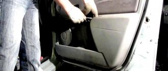
Removing the sliding door and disassembling its moving mechanism
We work together or three, as the door is heavy.
1. Using a wrench or a 14mm socket, unscrew the two bolts securing the door opening mechanism to the middle guide. Remove the bolts along with the plate.
2. Holding the door suspended, remove the middle door opening mechanism from it.
3. Using a 6-point hex key, unscrew the two bolts securing the door to the upper support.
4. Lowering the door slightly (2–3 cm), remove the lever of the lower door opening mechanism from engagement with the lower guide
5. Remove the door
6. Using a 14mm wrench, unscrew the three bolts securing the lever
7. Remove the lower mechanism lever from the door.
We install the door in the following sequence.
First, we attach the upper support to the door.
Then we install the middle guide mechanism on the door.
We install the lower mechanism lever on the door, having previously engaged the lever roller with the lower guide.
After installation, adjust the position of the door.
Replacing the door stop
The limiter must clearly fix the door in two open positions and not prevent the doors from closing.
Creaking, crackling and play of moving parts are not allowed.
We replace the faulty limiter.
Remove the door trim as described above.
Squeeze the holder and disconnect the speaker wiring harness from the door panel
Unscrew the four screws securing the speaker
Move the speaker to the side for the length of the wires
Disconnect the speaker wire connector and remove the speaker
Unscrew the two bolts securing the limiter to the instrument panel
Unscrew the bolt securing the limiter to the rack
After disconnecting the stopper, do not open the door at a large angle; the outer door panel may be damaged.
Remove the limiter through the speaker opening
Install the limiter in reverse order
Sliding door adjustment
It is more convenient to work together. We adjust the door if the door has been removed, as well as if its correct position is violated during operation. It is more convenient to make adjustments with the lock latches removed.
Door height adjustment
1. Use a 17mm wrench to loosen the locknut.
2. Rotating the adjusting bolt of the upper support using a 14mm wrench, raise or lower the front edge of the door, achieving a uniform gap between it and the middle pillar
Having adjusted the door to the required position, tighten the locknut of the adjusting bolt.
3. Using a 14 key, loosening the two bolts securing the door opening mechanism on the middle guide, raise or lower the rear edge of the door, achieving a uniform gap between the door and the side of the body. While holding the door in the required position, tighten the bolts securing the mechanism.
Adjusting the door position “in depth”
Having loosened the locknut of the adjusting bolt of the upper door support and moving the support within the adjustment slot, we move the upper edge in a horizontal plane, and then tighten the locknut.
Using a 12mm wrench, loosen the two bolts securing the lower arm with the roller and move the arm within the slot, adjust the position of the lower edge of the door in the horizontal plane, and then tighten the bolts.
If the described adjustments are not enough, we make additional adjustments.
Using a 14 key, loosening the three bolts securing the lower support to the door, move the support within the slots along the door, adjust the position of the lower edge of the door in the horizontal plane.
GAZ Gazelle Gazelle Valyat › Logbook › Ignition switch
We are changing the ignition switch. I decided to change it because... It often happened that the key slipped, and the engine was already running, but the starter was still turning. Plus, you would start, but the heater did not work, the low one did not light up (I had to move the key here and there) I CHANGED 25 MINUTES, THIS IS ALREADY THE SECOND REPLACEMENT, the first was on the first car, there changed the hour. I bought the cheapest one, did not take Nizhny Novgorod for 800 rubles, and it works fine (tested on an old car). Now I already know how to come up with something and modify it. I explain in detail, because if people are faced with a replacement for the first time, then it will be incomprehensible and problematic for them. So read and also change in 25 minutes))))) Disconnect the plug in advance. 1. We undress the steering wheel, remove the top plastic and the bottom one, the bottom one is difficult to remove, to do this, bend the steering wheel adjustment knob (of course, first of all, unscrew the 2 screws with a skate screwdriver). Sections: 2. You can’t remove the clamp, the factory nuts have no edges, we cut them mercilessly with a grinder, The main thing is to stop in time, otherwise you will cut the main steering column pipe. 3.Cut a small piece and it should fall off, or a couple of hits with a hammer. 4. For further convenience, I unscrewed the steering column itself. This is a long bolt that goes to the steering wheel height adjuster. It was unscrewed, there are 2 nuts on the left for 12, on the right there is a bolt head for 12. To remove this bolt, without any extra effort. Raise the steering wheel to the maximum up. When you remove the bolt, look and remember the position of the brace (which is at the head of the bolt). And then stick it in as well. 5. The steering wheel and steering column have fallen. Take out the old ignition. Give it to your neighbor or mother-in-law (complete with old keys). 6. We take a new bracket and make slots in the sidewalls where the heads of the tightening bolts will be. And these slots so that you can then easily tighten the 4 tightening bolts with a ratchet; if you don’t make the slots, the head on the ratchet will rest against the edges, and you won’t tighten the ignition as it should. Yes, and suddenly, again, you might have to remove the ignition yourself. 7. It’s just a matter of small things: put the left part on the steering wheel, attach the right one, screw in 4 bolts, tighten it to the maximum. We tie the steering wheel with a long bolt, do not tighten the 2 hooks too much, otherwise you can then adjust the position of the steering wheel to suit you. 8. Everything is assembled, hang up the plastic, connect the plugs, try to start it. AND MEGA IMPORTANT STEP))))) 9. “Wash” this ignition))))) Good luck on the roads, I’m waiting for comments and questions?)))))
Installation of doors and locks
The GAZelle sliding door has the following device:
- Side windows.
- Upholstery.
- Glass.
- Edge of the opening.
- External and internal handle.
- Lock.
Door lock device:
- A locking mechanism that closes the lock and secures it.
- Lever mechanism - for opening the lock from the outside or inside and locking it.
- Retainer tires that hold the system in place in an emergency.
Automatic rear door lock. It complies with safety standards. The locking mechanism consists of:
- mechanism base;
- rotor with finger;
- fist with finger;
- return springs;
- buffers;
- base cladding;
- spacer bushings.
The lock includes external and internal drives. Structure of the lock and its drives:
- Tractions.
- Clamps.
- Stopper lock drive.
- Stopper body.
- Stopper latches.
- Adjusting gaskets.
- Power off button.
- Lever arm.
- Lever mechanism.
- Locking mechanism.
- External handle socket.
- Latch.
- Tips.
- Stopper slider.
Locks are used to prevent theft of objects from inside the car and unauthorized access to the vehicle.
How to easily and quickly install a lock and other elements of the ignition system on a Gazelle?
The performance of the automotive ignition system (ISY) directly affects the functionality and operating condition of the vehicle engine. Accordingly, the failure of one of the system elements can lead to minor or even serious problems in the operation of the power unit. What is the operating principle and order of the SZ, how to replace the Gazelle ignition switch - read more about this below.
The principle of operation of the Gazelle ignition system
First, let's look at the operating principle of the SZ Gazelle 402 engine. In this case, we are talking about any models of this car - both with a 406 engine and 5-seater Gazelles. The principle of operation of the SZ lies in the accumulation and further conversion of low-voltage voltage into high-voltage voltage using a coil after that. After conversion, the coil transmits and distributes high-voltage voltage to the spark plugs of the system. The spark plugs themselves are used to generate a spark, which, in turn, is necessary to ignite the air-fuel mixture in the cylinders.
The main stages of the work of the SZ:
Pinout of Gazelle ignition switch contacts
Firing order
The connection diagram for the cylinders on the Gazelle, that is, the order of their activation, for the 406 engine is as follows:
Basic elements of SZ
Briefly about the main components of SZ:
Lock replacement and repair
If, when you try to turn on the key, nothing happens in the lock, that is, the engine does not start, the problem may lie in a poor connection of the contacts. You can try to repair such a lock, but if this does not help, then the device will have to be changed (the author of the video is Sergey Vishnyakov).
Replacing the contact group
This task is performed as follows:
Photo gallery “Changing the contact group”
Changing the lock
To completely change the lock, do the following:
Video “Features of connecting the ignition switch in a Gazelle”
What should be taken into account when connecting the lock contacts - see the video below (author - Budni Gazelista channel).
Main causes of jamming
A Gazelle is a car that is mainly purchased for business. In Russia it is used as a minibus for personal purposes or transporting a large number of people in the form of a private cab. To open the structure without damaging the door leaf when the Gazelle side door guide is jammed, you need to choose the appropriate method of procedure. It is calculated depending on the situation and the nature of the fault. Causes:
- Damage to hardware. The door may stick. Sometimes the pawl flies off, which creates a smooth motion of the carriage.
- The middle or rear pin, which is responsible for fixing the blade during opening, sinks.
- One of the passenger door electronics has burned out. It may short out due to frequent vehicle washing or climatic conditions.
- Careless handling of the structure. Passengers often slam the door forcefully when leaving the vehicle.
- Lack of maintenance of the sliding canvas. The door may jam. Diagnostics, prevention, lubrication and adjustment work should be carried out regularly.
It is more difficult to find a breakdown when there are no visible causes, but the prerequisites are always present. If the door does not close well or cannot open the first time, there are extraneous noises and squeaks, then a comprehensive diagnosis should be carried out.
It is recommended to pay attention to the position of the door: the presence of deformation, the size of the gap between the leaf and the body, overhanging or skewed. Deformation may occur if the Gazelle was involved in an accident. In this case, the structure is first straightened, then the mechanisms are repaired.
GAZ 31 Transitional › Logbook › 02.19.15. Replacing the door lock cylinder.
Good evening! I’ve been making frequent recordings, maybe I’m already tired of it? Well, since you came here, read and look at the pictures. )))
Today I went to the garage to try on yesterday's new clothes. I grab the BC... and in response there was silence, I didn’t even blink (((I started scratching my turnip, something was wrong. This shouldn’t happen. I remembered that before that, my self-diagnosis (with a jumper) didn’t work either, which means something is missing For the BC to work, 3 contacts from the diagnostic block are needed: “2” - +12V, “11” - K-Line and “12” - ground. Judging by the diagram
+12V is constant and is taken from the ECM relay, and since the engine is running, that means there is “+”. All that remains is to check the ground and the K-line. I'm 95% sure that the problem is Massa, because... if there were no K-line, then the BC should have blinked anyway. And as luck would have it, there was neither a multimeter, nor a tester, nor a piece of long wire to tie to the light bulb. Therefore, I left the chain testing for later. I now have just 5 days off))): February 19 Local New Year - Sagaalgan, working day February 20 - moved to 28.02. well, February 21,22,23 like in the rest of Russia)). So I think there will be enough time.
I sat and scratched my turnip... Well, okay, one thing didn’t work out, so there are plenty of them and others. There will be enough spare parts purchased new and not supplied for another month)). I decided to take care of the essentials. I have been worried about the issue of locking and unlocking doors for a long time. I only have one key, and it’s pretty worn and regularly jams. Sometimes you stand at the door for half a minute or a minute, turning it back and forth until it gets into the right position. In general, I took out a set of larvae from 3102 from the package with spare parts and started replacing. I think almost all Volgovodians know how to change larvae, but for those who don’t know, look at the pictures. I removed the door card, and for some reason I unscrewed the “loaf” O_o. Loosen this screw here
I pulled out the larva, and we heard that something fell inside the door. We climb into the door, feel for this “something,” take it in our hands, and together with the larva we go into the light. This “something” turned out to be a retainer.
We pull out the cotter pin from the larva, disassemble it into parts, and lay it out. You should get 4 parts: the body of the larva, the larva itself, the pin and the cotter pin.
We take a new face and compare it with the old one. Once again we note how shitty the quality of spare parts is now. They are even different in height and casting defects are not removed.
We close our eyes and put this g...but into the body of the larva. We check that the protrusions on the body are facing up, and the key inserted into the cylinder is facing down with its teeth.
We combine the holes in the cylinder and the pin, put the cotter pin in place
Now the most difficult part: We insert the cylinder into the door, put on the latch and “by touch” insert the pin into the door latch hole.
Now you need at least three hands, or two very flexible ones. We hold the cylinder with one hand, with the second hand we set the lock in the correct position, with the third hand we turn the screw (which was loosened at the very beginning). We insert the key and check whether everything works correctly.
We take out the key, spray a little WD40 into the cylinder (NOT ADVERTISING, other liquid lubricants can be used)
We insert the key again, make three or four closures and... That's it. Repeat for the second door.
So, for comparison, what was the key and what is it now.
We put one new key on the ring to the ignition key, and the second one in the wife’s jewelry box. She watches over them) Well, she’ll look after the key for one thing))
I also haven’t removed the old key yet; I haven’t touched the trunk cylinder yet. Although I rarely use it since I installed the electric lock.
Something like that. The work was not performed for protection, but solely for personal convenience. The Volgovsky larvae leave much to be desired; they say that they can be opened with the key from another Volga (I haven’t tried it). And to hell with them. For the purpose of theft, anyone who needs it will not climb into the Volga; it is better to climb into the neighboring Zhulka. And if they notice something interesting in the cabin, they won’t bother opening the doors, they’ll open the windows and look for candles.
UPD from 04/11/15 Still, it broke. I had to repair it
The quality of the ignition system of foreign and domestic cars affects the performance of cars. Obvious problems result in frequent failures or the inability to start the engine in a timely manner. In most cases, the problem is caused by the electrical part of the ignition switch.
Trucks of the GAZ family and buses can fail their owners due to burnt or oxidized contacts. To restore the functionality of the unit, we recommend studying what the Gazelle ignition switch circuit looks like.
How to open a gazelle without a key?
You can open Gazelle using the following methods:
To use this method, you need a wedge (wooden) no more than twenty-five centimeters long and up to four centimeters thick, and a metal rod with a hook at the end.
Using a wedge, you need to bend the edge of the door in the upper corner; for this purpose, it must be carefully driven between the frame and the stand. If you are not careful, you will likely ruin the door seal and remove some of the paint with the wedge.
You need to insert a rod into the gap that appears after driving in the wedge and use the hook to turn the blocker. If you don’t have a wedge, you can try to do without it; to do this, you need to press on the glass with your hands and try to lower it.
If you succeed, you will need to insert a screwdriver into the slot and widen it. Work very carefully as you may damage the window. Then everything is repeated, as in the example described above.
- Using an electric drill
This method is good because it allows you to quickly get into the car, but it is not always profitable, since after this you will have to change the lock. The essence of the method is to drill out the core of the lock with an electric drill, which makes it easy to open the door.
You need to take a piece of flexible but rigid wire eighty centimeters long and form a hook at one end. The length of the hook after bending should be approximately ten centimeters.
When the hook is ready, you need to bend the seal from the side of the door handle and insert the wire. Next, you need to engage the door rod on which the lock button is located. Once you have the pull hooked, you can pull the hook up and open the door.
By contacting a specialized company for emergency opening of locks, you get careful and professional work and do not risk damage to the lock mechanism and the integrity of the upholstery, rods and hooks.
Screwdriver and seal
If the side door on a new Gazelle is jammed in winter, you can still try to open the door without a key; for this you need:
- Use a flat-head screwdriver to pry out the glass seal.
- Manually lower the element.
- Enter the car through the passenger door next to the driver.
Using a screwdriver, you can unscrew the side door bumper; the round fasteners on the Gazelle are hidden under plastic plugs.
If you have a strong wooden stick or an iron rod with a hook at the end at hand, you can try using them to unlock the mechanism. The wedge needs to rest between the frame and the stand. It is important to act carefully so as not to damage the paintwork. When a gap appears between the glass and the seal, you can lower the window or press the lock.
How to easily and quickly install a lock and other elements of the ignition system on a Gazelle?
The performance of the automotive ignition system (ISY) directly affects the functionality and operating condition of the vehicle engine. Accordingly, the failure of one of the system elements can lead to minor or even serious problems in the operation of the power unit. What is the operating principle and order of the SZ, how to replace the Gazelle ignition switch - read more about this below.
The principle of operation of the Gazelle ignition system
First, let's look at the operating principle of the SZ Gazelle 402 engine. In this case, we are talking about any models of this car - both with a 406 engine and 5-seater Gazelles. The principle of operation of the SZ lies in the accumulation and further conversion of low-voltage voltage into high-voltage voltage using a coil after that. After conversion, the coil transmits and distributes high-voltage voltage to the spark plugs of the system. The spark plugs themselves are used to generate a spark, which, in turn, is necessary to ignite the air-fuel mixture in the cylinders.
The main stages of the work of the SZ:
Pinout of Gazelle ignition switch contacts
Firing order
The connection diagram for the cylinders on the Gazelle, that is, the order of their activation, for the 406 engine is as follows:
Basic elements of SZ
Briefly about the main components of SZ:
Lock replacement and repair
If, when you try to turn on the key, nothing happens in the lock, that is, the engine does not start, the problem may lie in a poor connection of the contacts. You can try to repair such a lock, but if this does not help, then the device will have to be changed (the author of the video is Sergey Vishnyakov).
Replacing the contact group
This task is performed as follows:
Photo gallery “Changing the contact group”
Changing the lock
To completely change the lock, do the following:
Video “Features of connecting the ignition switch in a Gazelle”
What should be taken into account when connecting the lock contacts - see the video below (author - Budni Gazelista channel).
Removing the right rear door lock
When the driver was able to get inside, it is necessary to open the lock. If this cannot be done using the standard method, you will have to disassemble the door card. To do this you will need a set of screwdrivers, a socket wrench number 10, 8, and pliers. Algorithm:
- Remove the plugs to unscrew the handle fasteners.
- Unscrew the bolts with a wrench.
- Remove the screws that hold the limiter clamp.
- Remove the limiter bracket.
- Remove the inner handle rosette.
- Unfasten the top row of clips that secure the trim.
- Turn off the switch rod.
- Remove the cotter pin securing the leash.
- Loosen the lock switch fastenings with a 8 key.
- Unfasten the bottom row of clips. Remove the panel.
Once access to the lock is gained, it can be removed or the lock removed without dismantling.
Installation of central locking in Gazelle minibuses
Most minibuses produced today are equipped with a sliding passenger door. In a regular car, even if central locking is not initially provided, it will always be easy to install actuators and connect them to the lock rods. Installing a central lock on a Gazelle, if we are talking about a sliding door, looks a little more complicated. But still, this task is completely solvable, even for beginners. The main thing is that when installing the actuator, the door itself does not need to be removed. Further, all operations are considered in more detail.
Removing and installing a window regulator
You will need tools: TORX T25 and 10 wrenches, a special plastic mounting blade or a flat-head screwdriver.
We lower the glass to about halfway.
Remove the door trim and soundproofing gasket
Loosen the two fastening bolts and disconnect the glass from the slide
Raise the glass and secure it with tape in the upper position
Unscrew the bolt securing the front glass guide
We turn the guide so that it can be removed through the mounting hole in the door, and remove it from the door
Replacing the outside door handle
Remove the door trim as described above.
Raise the glass up
Unscrew the four screws securing the handle
To gain access to the two rear and front upper handle fastening screws, technological holes are provided
We move the handle, mark the position of the tip of the lock drive rod in the spring handle holder
Disconnect the rod end from the spring holder of the outer handle
Remove the handle
Before installation, lubricate the handle spring with lithol
Install the handle in the reverse order.
We install the rod end according to a pre-made mark.
Device and tools for work
Adjustment of the Gazelle front doors is shown after their installation. To do everything correctly, you should study the principle of operation of the canvas. Most Gazelles have a sliding door; let’s take a closer look at the design:
- the sash opens to the side, parallel to the body;
- special fastenings help to travel;
- due to the clamps, bearings and running belt, the movement is smooth;
- during closing, the canvas reliably fixes the closing device;
- movable handles allow you to open the door from the inside or outside if the door is not locked.
For self-repair, you will need key No. 6, 14, 17.
How does the ignition system work?
The system for models with a 402 engine functions similarly to those systems installed on cars with a 406 engine or in a five-seater vehicle. The main tasks performed by the installation are based on the accumulation and subsequent transformation of voltage from low voltage to high voltage. Coils are used for this.
The voltage converted from the coil is sent to the spark plugs screwed into the block. A spark is formed between the spark plug electrodes, which ignites the combustible mixture. The main stages for the Gazelle ignition system are:
To start the rotation of the engine crankshaft, a starter built under the hood is used . Voltage begins to be supplied to it after turning the key to its extreme position.
Removing and installing the side door
Having the necessary equipment, assistants and work space at hand, the removal of the structure occurs in several stages:
- Removing the middle guide - remove the facing panel. To do this, you will need to use a 14mm wrench to remove the screws, then the retaining plates.
- To remove the middle mechanism, the door is held suspended.
- Use a hexagon to unscrew the top bolts that connect the sash to the main support.
- The door lowers a little. This allows you to remove the lever of the mechanism, which is located in the lower part.
- The web is removed after unscrewing and removing the three screws on the lever fastener.
Reinstallation is performed in reverse order. It should be noted that in this process the upper support is attached first, and then the lower one.
How to remove the trim
- Use a thin screwdriver to pry off the 2 handle plugs.
- Using a socket or a 10 mm tubular wrench, unscrew the 2 bolts and remove the handle.
- Unscrew the screw securing the lock handle socket.
- When removing the socket, pull the handle towards you.
- Having pressed out the rubber socket of the window lifter handle, use a needle to press out the locking pin and remove it from the hole.
- The handle with the socket is removed.
- Using a screwdriver, remove the 8 plastic upholstery clips.
- The door trim is removed.
- Carefully remove the soundproofing gasket, which is glued to the sealant.
You can replace the old trim with the same one as the door trim on GAZelle Next.
Removing the sliding door opening mechanisms
Using a wrench or a 8-mm socket, unscrew the four bolts securing the upper guide casing.
We remove the casing. After loosening the locknut, unscrew the bolt securing the upper support to the roller carriage (see below “Adjusting the sliding door”).
Disconnect the upper support from the carriage.
Remove the carriage with the roller from the top guide.
Using a 10mm socket, unscrew the four bolts securing the upper guide.
Remove the top guide.
Using the same key, unscrew the two bolts securing the upper guide support to the body.
By prying the 12 clips (see section “Removing the sliding door trim”), remove the hardboard trim above the right rear wheel arch.
Using a “13” socket, from the interior side, unscrew the four nuts of the studs securing the middle guide.
Gazelle Business Ignition
Removing the ignition switch. Gazelle business!
And so on in order.
Don’t break the lock, (if you have a spare key) it’s a very expensive pleasure to have a new lock, we have 2300 rubles + two locks for it on the body.
In general, it took me 15 minutes to remove the lock while traveling.
We unscrew the bottom plastic cover of the lock, two bolts, and 4 self-tapping screws. Remove it.
We remove the clamping ring from the lock, and the contact group falls out on its own.
Now we unscrew the two countersunk bolts, they unscrew easily, I had an ordinary screwdriver and a hammer, we put the screwdriver like a chisel into the edge of the countersunk one, and hit it with a hammer, and it slowly unscrews, it took me five minutes to unscrew these two countersunk ones (now I installed the usual ones, with edges, I don’t see the point in installing hidden ones, because with edges it seemed to me that I took longer to tighten, it’s more difficult to get there with a key)
Now the main thing is that without the lock itself, the console of switches, turn signals and wipers will not be held in place; the lock is a clamp to the steering shaft. In order for this console to be in place, I put the lock in place, and so that it does not lock the steering shaft, I placed a thick cardboard that prevented the lock from flying out and jamming the shaft.
Advertisements!
Advertisements for advertising purposes from Vasilich:
There is always an iProg USB and motorola adapter on sale that supports a large number of motorolas, as well as NEC and TMS, you can buy it here
Attention to all iProg USB owners. I'm starting the summer 2014 update of tracing paper and motorcycle adapters, read the details here
For owners of motorcycle adapters, we run NEC VDO via 4 wires, see here.
On sale there is a CAN-BLOCKER for winding up mileages on a Mercedes, with locks on a NEC processor, more details here
Gazelle business scheme
The electrical wiring of the Gazelle business consists of four harnesses: front, rear, instrument panel harness and engine control system harness. All harnesses are connected to the front wiring harness using connectors. The connection between the engine wiring harness and the front wiring harness is the same regardless of engine type or trim level. If we compare the Gazelle business scheme with the schemes of previous models, we will not see any big changes. Although it’s worth dwelling on this a little.
The first difference will make it much easier to replace the wiring or part of it. The fact is that in previous models, the front harness and the instrument panel harness were connected to each other not only by connecting connectors, but also on fuse blocks. Gazelle business harnesses are connected only using connectors. The next difference is a slightly more complicated heater switching circuit. This is due to the use of an electronic control unit and a variety of gear motors for remote control of the dampers and heater tap. There is also a slight difference in the connection diagram for external lighting and headlights. Another significant difference is the presence of a relay and fuse box. The diagnostic connector is also located in the same block.
There are also minor changes in the arrangement of circuit elements on the car. We have already mentioned the relay and fuse box, which now houses all the relays, and is not mounted under the steering column as on previous models. The windshield wiper relay is also located there, which was previously located on the left wing in the engine compartment. The turn and hazard warning relay is now located on the steering column under the top cover. The hazard warning button is also embedded there. Other changes are related to the location of the controls and are perhaps not worth dwelling on.
The Gazelle business engine diagram depends on the installed engine. Most often they are equipped with a UMZ 4216 gasoline engine with a Mikas-10.3 (11.3) ECU. The CUMMINS ISF2.8 diesel engine is also installed as standard. On request, ZMZ 405 engines with Mikas-11 (12) ECU can be installed.
Traffic regulations: Use of special signals, hazard warning lights and warning triangles
Measures to prevent blocking
To ensure that the door can close correctly even after long-term use, it is important to timely adjust individual elements and take care of the car. Basic rules and actions:
- You should open the Gazelle door carefully to avoid slamming.
- Carry out lubricating actions, additionally use an anti-corrosion substance.
- It is good to dry the Gazelle after washing in winter.
- Adjust the door, lock, handle using special bolts on the stand.
- Periodically check the operation of the drive.
You should also remember to promptly change accessories that have worn out. The price of the sliding door kit is 1000 – 2000 rubles, depending on the manufacturer.
How does the ignition system work?
The system for models with a 402 engine functions similarly to those systems installed on cars with a 406 engine or in a five-seater vehicle. The main tasks performed by the installation are based on the accumulation and subsequent transformation of voltage from low voltage to high voltage. Coils are used for this.
The voltage converted from the coil is sent to the spark plugs screwed into the block. A spark is formed between the spark plug electrodes, which ignites the combustible mixture. The main stages for the Gazelle ignition system are:
To start the rotation of the engine crankshaft, a starter built under the hood is used. Voltage begins to be supplied to it after turning the key to its extreme position.
How the central lock works
Mechanical door locks are equipped with a so-called “pawl” or button. There is a rod from the button to the main mechanism; it is made in the form of a wire rod. If this rod is moved by a motor, the state of the lock (open/locked) can be controlled. This is what is done in practice if you install the actuator:
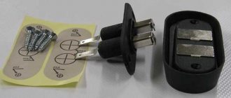
For a sliding door, as is easy to understand, the task becomes more complicated: it will not be easy to connect the wires to the electric motor. Typically, a detachable contact is used, which is designed specifically for buses.
The kit shown in the picture costs about 300 rubles.
Now we can talk about what types of actuators there are. The contacts on the door are connected to two wires, which means you can only install a two-wire actuator and not any other. Such a device, of course, contains an electric motor inside. According to reviews, not the most powerful electric drive is suitable for the Gazelle sliding door. The force of 6 kg developed by it can be considered sufficient. The current strength for such devices does not exceed 4 Amperes. You can also buy three-amp actuators that develop less force (4-5 kg).
Control unit for the GAZelle Next door locking system. Scheme.
Control unit for the GAZelle Next door locking system. Scheme.
The control unit (A21R23.3867100 or C41R11.3867100 or A31R22.3867100-20) for the door locking system is installed on the instrument panel amplifier near the steering column, designed for simultaneous (central) blocking (locking) or unlocking (unlocking) of the front doors (for control units А21R23.3867100 and С41R11.3867100) and all doors (for the control unit А31R22.3867100 – 20) of the vehicle and delays and smoothly extinguishes the interior lamp of the cabin and the lamp of the running board. The control unit has the function of protecting the lock motors from overheating caused by excessively frequent locking/unlocking of doors. In this case, the central locking stops working for a few minutes, after which its functionality is fully restored.
Installation of the door lock system control unit.
1 – base of the instrument panel; 2 – rear power steering bracket; 3 – screw, 4 – door lock system control unit.
Electrical diagram for connecting the A21R23.3867100 control unit for the door locking system.
1 – door lock control unit; 2 – open door indicator in the instrument cluster; 3 – cabin ceiling; 4 – driver’s door actuator; 5 – passenger door actuator.
Door lock control unit block.
Electrical diagram for connecting the control unit C41R11.3867100 for the door locking system.
1 – control unit for electric door locks; 2 – signaling device for open cabin doors; 3 – cabin ceiling; 4 – driver’s door gear motor; 5 – passenger door gear motor; 6 – passenger door gear motor.
Control unit block for electric door locks.
Front door lock block.
Electrical diagram for connecting the control unit A31R22.3867100-20 for the door locking system (GAZelle Next TsMK).
1 – control unit for electric door locks; 2 – switch to lock/unlock rear doors; 3 – open door indicator in the instrument cluster; 4 – driver’s door actuator; 5 – passenger door actuator; 6 – sliding door actuator; 7 – swing door actuator; 8 – lamp for lighting the steps; 9 – cabin lighting; 10 – cargo compartment lighting lamp.
We fix the actuator inside the door
First we need to consider how exactly the standard casing is dismantled. We note the following: it is impossible to gain access to the pawl rod without removing the main lock completely. These are the design features of Gazelle cars. The photo will show what a lock with a rod looks like, and you will understand what you need to connect the actuator to. Let's start dismantling.
How to remove the trim yourself
All actions listed below are illustrated with one photo.
The stopper fastening is unscrewed with a 12mm key, and a screwdriver is used to dismantle the socket. The sequence can be considered in detail:
- Using a spanner wrench, unscrew the two screws securing the stopper.
- Using a flat-head screwdriver, unscrew the screws holding the socket of the internal handle.
- Remove the stopper and socket.
- By prying up the round pads with a screwdriver, they are completely dismantled, and then the casing is removed.