The clutch is one of the key components of any vehicle. Correct gear shifting and, consequently, the movement of the tractor depend on its serviceability. Smooth running, ease of control, optimal load distribution between the engine, chassis and power take-off shaft also depend on the performance of this important unit. Timely adjustment of the T 40 clutch will ensure comfortable control of the tractor and serve as a reliable prevention of breakdowns. The T-40 tractor is a legacy of the Soviet automobile industry. Among the priorities in the development of components and assemblies was the ability to perform maintenance and repair literally in the field. This is one of the reasons why these tractors are still in demand: all the necessary work can be done yourself, in the garage, reducing the cost of professional service. Clutch adjustment is one of those operations that is easy to master.
Clutch T-40
The main purpose of this mechanism is to disconnect the chain, with the help of which power is transferred from the engine to the gearbox, as well as for its short-term disconnection, in order to ensure the possibility of quick and shock-free gear shifting and a smooth start of the tractor.
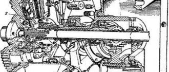
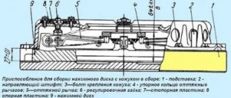
Diagram of the T-40 clutch basket and its operating principle
The clutch mechanism itself consists of the tractor main clutch and the PTO clutch, each of which is made as a dry single-disc type with permanently closed separate control. Below we present a diagram of the clutch (basket) for the T-40 tractor and consider its operating principle.
This mechanism allows you to transfer rotation and the torque itself from the engine to two different flows of motion and to the drive of the working parts. This ensures that the tractor shifts gears without stopping it and turning off the PTO.
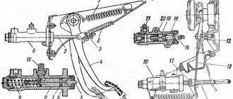
The T-40 clutch is installed on the engine flywheel and consists of a driven disk (17, 18), a pressure disk (9, 16) and a drive disk (8). With the help of pressure springs (6), the driven disk is constantly pressed against the drive and the flywheel itself. When you press the clutch pedal in the cabin, the lift with the bearing (24) moves.
In this case, the bearing presses the lever (21), thereby disengaging the clutch.
By pressing the clutch pedal of the power take-off shaft, the sleeve with the bearing (15) moves, it presses the lever (23), and the clutch of the power take-off shaft is disengaged.
Why does the clutch paw break?
periodically breaks the clutch foot, bends or pierces.
I bought another one, but it has a place for the stop (ball) about three centimeters closer to the axis of the input shaft. Logically, the pedal should become much softer, but I just can’t understand what it should rest against because... I currently have that same stop (ball) located on the clutch housing, and when trying on a new fork it should be located on the box. Anyone know what the modification is or what I need to change, please respond. and :confused:then I have already replaced three clutch forks (and pumped up my left leg) digital 4026 Volgovsky box 4 mortar completely synchro. The clutch is a petal type (changing the basket did not make it any easier) On the 4st gearbox, there shouldn’t be a ball, it can only stand on the casing. When installing the petal basket, a 3mm thick washer must be placed under the ball. For a soft squeeze, I welded the ear on the clutch pedal axis.
periodically breaks the clutch foot, bends or pierces. I bought another one, but it has a place for the stop (ball) about three centimeters closer to the axis of the input shaft. Logically, the pedal should become much softer, but I just can’t understand what it should rest against because... I currently have that same stop (ball) located on the clutch housing, and when trying on a new fork it should be located on the box. Anyone know what the modification is or what I need to change, please respond. and :confused:then I have already replaced three clutch forks (and pumped up my left leg) digital 4026 Volgovsky box 4 mortar completely synchro. paddle clutch (changing the basket did not make it any easier)
A fork with a groove shifted towards the release side for a support under the petal basket. The supporting soldier is moved to another hole on the bell. If the petal basket is now standing and is so tight, then either it requires replacement or just rearranging the support will be enough. Although I'm more inclined to replace the basket
or maybe it’s that the bell is without a second hole (because according to the owner’s story, there was once a 40210L engine there. I got it with some kind of dead engine with a broken number. I installed the engine from Volga 3110. At the same time, the bell still rocks in place with the car )
The very old ones didn’t have them, then there were no leaf baskets either: D I now have a 410pihun, it has a VALEO leaf fork with an offset support and, accordingly, the support pin is twisted. Re-drilling is not a problem if there is no second hole!
thanks for the info. First, I’ll pick out the dirt, and if there is no treasured hole, I’ll have to pick it out)))
If you have anything, write me. I’ll send you the dimensions and a photo of where the hole should be: D
Source
Recommendations for use
In order to extend the service life and protect the mechanism from premature wear, follow these simple instructions:
• Do not unnecessarily disengage the clutch and do not keep it disconnected for a long time while the engine is running;
• There is no need to keep your foot on the pedal while moving;
• Disconnection must be done quickly, pressing the pedal all the way;
• Switching on must be done smoothly and without any delays in the intermediate position;
• It is necessary to carry out adjustment work on the pedals in a timely manner.
Adjusting the T-40 clutch
Over time, the driven disc linings wear out and the ends of the arms come close to the bearing, reducing the clearance. When the gap is minimal, the paws of the levers will begin to touch the bearing race, and this will increase friction and increase wear.
The normal clearance between the release lever and the outlet thrust bearing should be 4 mm.
Adjustment of the clutch must be carried out when the pedal stroke is reduced to 2.5 cm, and they can be done in two ways: using rods or bolts.
Traction adjustment
Follow our instructions carefully:
• First, open the upper hull hatch;
• Unsplit the traction fork axis;
• Remove the lever fork;
• When screwing the fork, set the length so that when the fork is connected to the lever, the gap becomes nominal - 4 m
• Put the fork axle in place and pin it;
• Put the hatch cover in place.
Bolt adjustment
If it is impossible to change the rod length, then the tractor clutch must be adjusted using adjusting bolts, for this:
• Open the top hatch;
• Unscrew the nut (22) of the bolts;
• Since the adjustment is usually made using the length of the rod, it is necessary to return it to its original position, if the adjustment was not made this way, then skip this point;
• Unscrewing the nut (22), move the end of each clutch lever toward the engine by 5-8 mm to connect the clutch lever and the thrust fork;
• Next we pin the fork axis;
• The final adjustment process is carried out using a gap feeler between the end of the release lever and the release stop of the offset bearing up to 4 mm
The gap difference should not be more than 0.4mm.
See the control diagram for the main clutch and power take-off clutch.
Remember, when disassembling the drive, you need to correctly install the servo springs, which reduce the force on the pedal. The spring is placed in the hole of the bracket so that the pedal is in the upper position.
Key indicators for adjustment
The spring is installed in one of the holes in the bracket so that the pedal is held in its uppermost position, and when pressed, it reduces the force on the pedal.
Related Posts
Why on MTZ, when you press the clutch, the release lever does not spin, but when you don’t press it with your hands, it spins normally?
Please tell me, I have this problem: on MTZ, when you press the clutch, the release does not spin, but when you don’t press it with your hands, it spins normally. The new release bearing is in place. What could it be?
I installed a dispenser on the MTZ-80. Why do the wheels turn on their own when turning and the steering is heavy?
Guys, please tell me. , I installed a dispenser on the MTZ-80; when turning, the wheels turn themselves and the steering is heavy.
We repaired the PTO on MTZ 80. Why is there a whine in the bridge when you turn off the PTO, but as soon as you turn on the PTO everything is fine?
Hello everyone, guys, please tell me, maybe someone has come across a problem, the PTO on the MTZ 80 was broken, I figured it out, but now another problem has emerged, when you turn off the PTO there is a howling sound in the bridge, as soon as you turn on the PTO everything is fine. What could it be?
MTZ80 converted to MT82 (front drive). Why does it make a lot of noise when the tractor drives at low or high gears?
Hello, good people. Half a year ago I bought an MTZ80 converted to MT82 (front wheel drive). The problem is that when the tractor drives in low and high gears it makes a very loud noise, it’s impossible to drive, and for one thing it infuriates you to the point of horror. The rear axle was dismantled, everything was fine, but alas, the noise remained the same. Noisy: Low 4.5, high speeds 7.8 high speeds. Thank you all in advance!!) I'm waiting for your comments on how to fix it. Thanks in advance.
MTZ 80 tractor. Why is there a knocking sound like a periodic hammer when the engine is running? When the injector nut is loosened, cylinder 4 does not respond.
Good day everyone! Tell me what could be! Tractor MTZ 80, when the engine is running you hear a knocking sound like a hammer intermittently, when you loosen the nut of injectors 4 the cylinder does not react, the tractor works as it worked, and you loosen 1,2,3 one by one, the tractor loses power and the knocking stops, but as soon as you tighten it the knocking comes back and the tractor runs smoothly again but with a knocking sound.
Why does the gas jerk at idle? Mtz 80
Guys, tell me why the gas jerks? At idle. Mtz 80
Why is the clutch tight on the MTZ-80? The basket and disk are new.
Good day to all. My MTZ-80 has a tight clutch. The basket and disk are new. He squeezes his neighbor's hand. And in my case, my leg aches in the evening. What is the problem?
Mtz 82.1 I changed the disc, basket (analogue), release lever - adjusted it according to the book to 28mm. Why is there no clutch? The gap from the presser foot to the release lever is not 3mm.
Great everyone! Clutch. MTZ 82.1 changed the disc, basket (analog), release lever - adjusted it according to the book, rolled it 28mm, assembled it, but there is no clutch. The gap from the paws to the release lever is large and cannot be adjusted by 3mm. I put the disk in, the original basket, the same thing. The distance from the presser foot to the release lever is not 3mm, only 6.7mm. What is the problem, has anyone encountered this problem? Thank you
At the MTZ 80 checkpoint there was a high one, but not a low one. I stopped the slide on high. Why is there now an extraneous sound in the gearbox when under load?
Hello everyone, guys, please tell me, at the MTZ 80 checkpoint there was an increased flight, but no lower one. I stopped the rocker at a higher speed, now under load the gearbox starts to do something (duk), when you drive it whines from time to time, what could it be?
Maintenance of the clutch of tractors T-40 and T-40A
N
It is necessary to periodically lubricate the clutch, adjust it, as well as timely tightening of threaded connections.
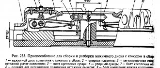
Rice. 50. Clutch design for tractor T-40 and T-40A.
a) – The main clutch is disengaged, the clutch of the independent PTO drive is engaged;
b) — The main clutch is engaged, the clutch of the independent PTO drive is disengaged;
1) – PTO clutch pedal axis;
Why does the engine knock and what to do about it?
The reasons for the appearance of knocking noises in the operation of the engine of the T-40 tractor are as follows:
- Valve clearance too large. The backlash adjustment must be made in accordance with the technical manual.
- Wear of piston rings in height. Failed parts must be replaced.
- Shocks in connecting rod and main bearings as a result of increased clearance. Grinding the crankshaft will resolve the problem. Worn out liners are replaced with new ones.
As for overheating of the unit, first of all you need to check the degree of tension of the cooling system fan belt. Perhaps it can be tightened up. If the belt is completely worn out, begins to delaminate or breaks, replacement is required. Also, the clogging problem may be caused by contamination of the fan protective mesh. In this case, the device works, but cannot properly cool the engine.
Source
How to adjust the clutch of a T-40 tractor: device and methods of adjustment
The task of the clutch in modern agricultural machinery is to provide the ability to quickly open and close the contact on the section of the chain between the engine and gearbox, as well as the controlled equipment. To effectively adjust the clutch, use the detailed instructions, a detailed description of the device and the principles of its operation.
For the T-40 model, the device diagram below shows in detail the location of all components, so you can independently understand the maintenance of the mechanism. The information is also relevant for the T-40A model, which has 238 1601130 YaMZ driven clutch disc and other similar equipment.
The result of the work will be a soft gear shift, in which the equipment moves off smoothly and does not make jerks while driving, as well as uninterrupted transmission of rotation from the engine to the auxiliary mechanisms.
Clutch device
The YaMZ 238 clutch, consisting of 2 parts, or a basket mounted on the engine flywheel, combines two closed mechanisms, controlled separately:
- Main clutch - drives the machine
- PTO clutch - activates the equipment through the power take-off shaft
Torque transfer is carried out in 2 streams - gear shifting and stopping of the tractor are carried out independently of the operation of the PTO, without requiring it to stop.
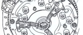
Clutch diagram
Unlike analogues that use the YaMZ 236 intermediate clutch disc, the unit is equipped with pressure and driven discs, pressed to the drive by springs. Using the pedals, the driver initiates clutch disengagement processes for operations with the gearbox or equipment. An outlet or bushing with a bearing moves levers that open the rotational energy transfer circuit.
What's the result?
As you can see, if you have certain skills, the process of replacing the clutch disc is not difficult. The most time-consuming operation is gaining access to the clutch itself, especially on front-wheel drive vehicles.
As for replacing the disc itself and how to correctly install the clutch disc, as well as the frequent question of which side to place the driven clutch disc, you need to take into account that the disc is placed towards the basket with the part where the damper springs protrude.
Read more: How to remove permanent marker from plastic
Manual transmission gears (speeds) do not engage after replacing the clutch: main reasons, settings and adjustments. Diagnosis of problems, useful tips.
How to replace the clutch on a DSG/S-Tronic robotic gearbox. Signs of the need for replacement, removal and installation of the DSG clutch, calibration and adaptation.
Double clutch: device, purpose, operating principle and features. How a dual-clutch transmission works, reliability, service life, pros and cons.
Clutch Adjustment Instructions
The main task that adjusting the tractor clutch solves is maintaining an optimal gap of 4 mm between the ends of the release levers and the thrust bearings of the lifter. Increased wear, which MTZ and 40a model spare parts also experience, occurs in the absence of the required gap between parts and direct contact of surfaces. A sign of a problem is that the system begins to slip. In addition, the free play of the pedal will be reduced to 25 mm. In normal condition, this parameter is 35-50 mm, and the working stroke is 70-90 mm (shown in the diagram below). The solution is possible in two ways, described below, and is suitable for adjusting both types of clutches. When assembling the drive, it is important to correctly install the servo springs into the provided cavity on the bracket. They support the pedal in its highest position and reduce the effort when pressing.
Traction setting
- Open the cover located on the top of the unit
- Remove the traction fork - release it from the cotter pin and remove the axle
- Set the distance to 4 mm - screwing the fork, change the length of the rod
- We return the cotter pin and install the axle, and then close the cover
Adjustment with bolts
- Having opened the cover, loosen the nuts of the adjusting bolts (in diagram 22)
- Return the original rod length if you previously calibrated using method 1
- Move the ends of the levers towards the engine by 7-8 mm, while unscrewing the nuts
- Align the basket lever with the traction fork, install and pin the axial part
- Use a feeler gauge to complete the gap adjustment - no more than 0.4 cm
- Measure the gaps between the levers - the maximum allowable difference is 0.4 mm
Related Posts
Why does the T40 tractor constantly tear off the clutch bolts? What bolt can I replace it with?
Hello everyone. On the T40 tractor, the clutch bolts constantly come off, who replaces them with what alternative bolts? Relatives constantly break the thread, the head, or the bolt itself. What bolt can I replace it with? They say the bolt from the head of the classic engine is suitable, but I compared the length of the bolts from the new original ones, the Zhiguli ones seem short.
Mtz 82.1 I changed the disc, basket (analogue), release lever - adjusted it according to the book to 28mm. Why is there no clutch? The gap from the presser foot to the release lever is not 3mm.
Great everyone! Clutch. MTZ 82.1 changed the disc, basket (analog), release lever - adjusted it according to the book, rolled it 28mm, assembled it, but there is no clutch. The gap from the paws to the release lever is large and cannot be adjusted by 3mm. I put the disk in, the original basket, the same thing. The distance from the presser foot to the release lever is not 3mm, only 6.7mm. What is the problem, has anyone encountered this problem? Thank you
Why do the clutch pads wear out on the MTZ 82? Releaser is new.
Good evening. MTZ 82 clutch feet are wearing out, I installed a new release lever! What is the problem?
How many revolutions should the Mtz PTO adjusting bolts be turned?
Hello tractor drivers! How many revolutions should the MTZ PTO adjusting bolts be turned? Thank you.
I installed a new clutch disc, the pressure plate is old. I collected everything and let down my paws. Why is the clutch bad?
Friends, please tell me what could be the reason? I installed a new clutch disc, the basket is old but still OK, I assembled everything, let the paws down, but the clutch is bad?
Maintenance
Just 3 main maintenance tasks for model 40 will keep the unit in perfect working order:
- Timely tightening of bolts
- Lubrication of parts subject to friction
- Checking the serviceability of threaded connections
The design of the roller bearing (12), the front bearing mounted on the crankshaft of the main clutch, as well as thrust bearings (in diagrams 15 and 24) allows you to reduce maintenance time. They do not require maintenance, since the factory lubricant is designed for the entire service life. After working for 230 hours, lubricate the contacting surfaces of the lifter and bracket through the grease nipple located on the left side of the body. Add grease to the bearing located in the lifter mechanism. Use grease, which is convenient to apply through a rod syringe. Please note that the nylon bushings on which they are installed also do not need lubrication control pedals and fork bolsters.
The engine does not start: looking for the reason
If you have difficulty starting the engine, the reasons may be as follows:
- Fuel line is dirty. It is necessary to wash and blow out all pipes. For particularly severe cases, you will need a compressor.
- Airing. In this case, it is necessary to get rid of air in the fuel system. As a rule, it is enough to fill the tank with fuel.
- Contamination of cleaning devices. If the filter is clogged, the products are washed or replaced, depending on how critical the problem is.
- Poor quality atomization of diesel fuel by nozzles. The devices may also be clogged and require cleaning. In case of critical wear, the injectors are replaced.
If the unit suddenly stops, we recommend paying attention to the presence of oil in the engine sump. If excess lubricant is found, remove the air plug and fill the tractor with fuel. As a rule, the problem of squeezing out oil is caused by airing. Also, random stopping of the internal combustion engine can occur due to contamination of the fuel line or fuel filters. The pipes and cleaning devices are cleaned. If the pipes are damaged, they must be replaced.
Recommendations for use
Wear on components can be reduced by extending the service life of the device by following simple instructions:
- Disengage the clutch only for operations on the gearbox or equipment.
- Avoid prolonged shutdowns with the engine running
- Press the pedal until it stops completely, quickly changing gear
- Take your foot off the pedal immediately after the operation
- Check and calibrate pedal movement regularly
- Stopping in an unfinished position will increase wear
- Return the pedal to its original position gently
After adjusting the mechanism gap, do not forget to change the linings of the driven disks, the thickness of which decreases with use.