The electric coupling and fan need to be replaced. We cut the diffuser. Once while moving I felt a slight vibration. Smoked. I dived under it and saw the fan with a piece of plastic torn out. What happened to this plastic is on the conscience of KAMAZ suppliers. This part is not cheap, 8 pieces, but due to the imbalance it is definitely necessary to change it, otherwise the bearing will first break, and then there will be “avalanche” wear of the shaft. Removing the intercooler, radiator and their accessories is a whole day of chasing a waffle, plus you need an assistant. This doesn’t suit me, so I move my horn. I decided to cut the diffuser. Bulgarian. And he made the right decision, although this work is delicate and requires a steady hand. As a result, I saved time and money. I hope this post is useful to someone. And now more details. 1).You need to unscrew the diff from the radiator: two M8 bolts on the right and two on the left. Upper. These are no problem. But if you unscrew it above the frame, the intercooler air ducts get in the way. Here you need a 13mm head with a small ratchet, otherwise you'll screw it out. 2). From the bottom of the pit there are two more M8 bolts on the left and right. There is no problem in unscrewing them. And when the diffuser is unscrewed and hanging on the propeller, it must be cut. Into 4 parts. North-South, and Left-Right. I advise you to use circles of the smallest diameter when making cuts. And be careful! On the right is the power wiring harness from the generator, and on the left is all the information from the sensors in the harness, plus blockages and other odds and ends. Don't hurt it! I didn’t take photos of the cuts, but I think the guys who are in the subject will understand where and how. The first cut is from above at the gear poker. The second is from the hole below near the radiator tensioner rod. Then you will have to aim above the frame on the left and right. As a result, the diff will be sawn into 4 parts, of which the upper two can be removed without any problems at all, and the lower two halves can be removed from the hole if you rub them a little between the lower pipes. And this is quite real! When I did this, I had no time for photos. Here is a photo of the cut diff. In this photo there are only two upper “quarters” since the lower ones were already in place...
I think that from the photo it is clear what is there and where to cut. We fasten the cut quarters with a simple metal plate with holes for short M6 bolts. This is the bottom mount
How does it work
Operating principle of hydraulic coupling:
- The running engine drives a pump-type wheel.
- The working fluid, which is located in the space between the blades, begins to spin and is then thrown away from the rotational axis to the periphery of the wheel mechanism.
- The liquid gains kinetic energy and speed. It moves in the same direction as the pump wheel.
- After this, the working fluid is shifted from the pump wheel to the turbine wheel mechanism.
- In the space between the blades, fluid particles begin to influence the turbines, causing them to rotate at angular speed. During this rotation, the fluid particles transfer their kinetic energy to the turbine wheel.
- The liquid moves to the periphery of the turbine mechanism, after which it returns to the pump wheel.
- The whole process is repeated again, circulating in the space between the blades.
- The fluid coupling activates the fan, which begins to blow on the radiator, cooling the working fluid.
- When the oil temperature drops, the clutch switch is activated and the fan stops running.
If the fan does not turn on, it is necessary to inspect the clutch mechanism for damage.
How to check a viscous coupling
The resource of this device in the design of the car is designed to cover 200 thousand km.
To check whether the fan and clutch are working well, you need to know the signs of malfunctions of these parts:
- If the engine heats up quickly, then this is the first sign of a viscous coupling malfunction. This appears due to the release of the gel or the untimely operation of the bimetallic plates. In this situation, when the motor gets very hot, the fan spins at a low speed, or does not turn on at all.
- The cooling fan starts spinning when the engine is still cold. This occurs due to changes in the properties of the gel, hardening of the lubricant and failure of other elements of the viscous coupling.
Reasons for failure or poor performance of a viscous coupling:
- The resource has been exhausted.
- Mechanical damage.
- The bearing has expired or broken prematurely.
- Axial runout of the fan impeller. Part of the propeller blade is broken.
- Lack of lubrication of the coupling shaft.
- Contamination of the coupling connection.
Advantages and disadvantages of a fan driven via a viscous coupling:
- A more reliable fan with a viscous coupling than an electric fan. It often happens that after winter, the electric drives of the fan fail and the electronic control circuit of the propeller is disrupted.
The advantage of a viscous coupling is that there is no electronics or electricity involved.
- The viscous coupling provides more power, the fan rotates at a higher speed. If the clutch sits rigidly on the crankshaft of the internal combustion engine, then the rotation speed is very high.
The power of the clutch connected to the crankshaft is several kW (kilowatts). And the power of electric fans has a power of several tens of watts. Thanks to this, a fan with a viscous coupling is used in agricultural machinery, military equipment, and special equipment.
Operation and Maintenance
The hydraulic coupling does not require special maintenance. However, it is important to choose the correct mode of its operation. The most optimal is the automatic operating mode, in which the fan drive turns on and off depending on the set temperature. The threshold temperature can be adjusted by adjusting the number of rings between the regulator and the thermal power sensor. Normally, turning on and off occurs automatically, providing the engine temperature necessary for stable operation. But sometimes you have to force the switch to only be on or off. Such operating modes of the fluid coupling are considered emergency; you should not operate the unit in this way for a long time.
Diagnostics of KamAZ fluid coupling
If the fan begins to work poorly, the reason may be in different parts of the fluid coupling. It is very easy to check whether the clutch itself is damaged or the problem is in the sensor or switch: if, when adjusting the threshold temperature or replacing the sensor/switch, the fan still does not work, then the malfunction occurred directly in the clutch.
If the diagnostics showed the presence of a coupling defect, the procedure will be as follows:
- The coupling must be removed together with the front cover
- Inspect the shaft and bearings
- Make sure the quality of the oil seal, gasket, O-rings
If the cause of the breakdown is wear of any of the above parts, then they are quite easy to replace. However, the wear of the fluid coupling may be irreversible, in which case a complete replacement is necessary.
Basic faults
If the hydraulic coupling does not work, the reason may be the following:
- Increased temperature of antifreeze or antifreeze in the cooling system of the power unit. This may be caused by: insufficient amount of working fluid in the system; insufficient tension of the water pump drive belts or their breakage; thermostat malfunction, contamination of the surface of the radiator part; slow rotation or stopping of the fan. In this case, it is necessary to replace all worn elements, rinse the system with clean water, adjust the belt tension, add antifreeze and fix the blinds.
- Reduced fluid temperature. This may be due to: the displaced position of the fluid coupling regulator lever; with a thermostat malfunction; with malfunctions of the blinds. It is recommended to set the lever to the working position, replace the worn thermostat, and repair damage to the hydraulic clutch drive.
- Antifreeze or antifreeze leak. In this case, it is necessary to replace the damaged parts of the sealing mechanism, change the plug gasket, repair or replace damaged parts of the pipelines and radiator.
Troubleshooting
In case of failures and malfunctions in the operation of the vehicle's electrical circuit, self-diagnosis can be performed in several different ways, for the implementation of which the KamAZ wiring diagram is also useful. In particular, the simplest types of testing may include checking the presence of voltage in a particular section of the circuit using a multimeter or other indicator. In general, diagnosing problems in the operation of an electrical circuit involves a certain sequence of actions.
First of all, one of the contacts of the test lamp or tester is connected to the negative terminal of the battery, the second to the connection of the circuit section being tested. It is recommended to try to make the connection as close as possible to the battery or a nearby fuse.
The appearance of a voltage value on the multimeter screen or the inclusion of an indicator light means the normal operation of the tested area, that is, that all elements are connected correctly and there is no need to carry out repairs. In this case, one should take into account the fact that the voltage in individual circuits is maintained only at a certain position of the ignition key in the lock.
The remaining sections of the electrical circuit are checked in the same way. Identifying a point where there is no voltage most often means that the source of the problem is located between it and the last good part of the system. Problems with electrical wiring on KamAZ 65115 Euro 2 vehicles and other models and modifications are most often caused by poor contact.
In addition, you can try to independently determine the presence of a short circuit. Having removed the corresponding fuse from the circuit, a voltmeter is connected to the free terminals with one probe. Having first made sure that all components of the circuit being diagnosed are de-energized and disconnected, move the connected wire
If changes in the position of the wire cause values to appear on the screen, we can conclude that there is a short circuit, most often resulting from a frayed insulating braid of the cable.
Why doesn't it turn on?
There are several reasons for this problem:
- Incorrect operation of the thermal power sensor
- The occurrence of shaft defects (weary splines, etc.)
- Bearing wear
- The switch is broken
If the fluid coupling does not turn on, it must be removed and disassembled to accurately determine the cause. If the problem is with the switch or sensor, then in many cases they will need to be replaced. You can also try adjusting the threshold temperature: perhaps it is set higher than normal, so the engine has already overheated, but the fan has not yet turned on.
How to replace
The procedure for disassembling and replacing the fluid coupling is as follows:
- Tilt the driver's cab to the second fixed position.
- Loosen the generator mounting nut.
- Remove the fluid pump drive belt.
- Remove the engine oil sump and oil cooler.
- Unscrew the mounting bolts and remove the filter responsible for centrifugal oil purification.
- Unscrew the front bracket screws and loosen the shoe nuts.
- Raise the front of the engine and place blocks of wood under the engine.
- Unscrew the bolts and washers where the front cover is attached to the cylinder block.
- Remove the fluid coupling along with the cover and casing.
- Install the new mechanism and reassemble, performing all steps in reverse order.
In order to change the KamAZ hydraulic coupling oil seal, you must:
- Unscrew all the mounting bolts from the pump wheel and remove it.
- Disassemble the pump.
- Pull out the worn out oil seal.
- Remove the pan and clean all filter elements with clean water.
- Open the housing of the pump mechanism and clean the mesh with oil or gasoline.
- Reassemble in reverse order.
Repair work
Repair of the hydraulic fan coupling is carried out in the following sequence:
- Install the hydraulic coupling on a special device. To do this, you can use a beam crane, suspension, etc.
- Unbend the locking mechanism.
- Remove the fan hub mounting.
- Press the hub off the hydraulic coupling.
- Unscrew the pulley mounting bolts and remove it.
- Remove the cuff and gasket.
- Remove the cuff bushing.
- Remove the ring from the spring mechanism.
- Remove the advance angle of the fuel injection system.
- Remove and press the driven wheel.
- Unscrew the studs from the threaded connections.
- Wash all contaminated parts with antifreeze or gasoline.
After cleaning all the elements, it is necessary to replace the worn parts with new ones. When the cause of the malfunction is unknown, you need to disconnect the fluid coupling from the fan, carefully disassemble the internal structure of the mechanism, blow out all the working fluid supply channels and check the torsional stability of all wheels. If any malfunctions are detected, fix them following the recommendations specified in the vehicle operating instructions.
Repair of KamAZ fluid coupling switch
The fluid coupling switch is the weakest point of this unit. The stability of the fan operation depends on it.
The problem is detected by the engine temperature: for example, if the temperature does not drop below 105 ° C, then most likely the switch does not operate correctly. The same reason may occur when the temperature drops below normal.
The operation of the switch is determined by the indicators of the thermal power sensor, which is in direct contact with the antifreeze, measuring the temperature and, if necessary, turns the system on/off. It is this element that is responsible for supplying oil.
Troubleshooting the switch operation involves adjusting the number of rings between the thermal power sensor and the regulator. Any experienced driver can handle such work; the fault can be easily fixed with your own hands. Most often, it is necessary to change the threshold temperature when there is insufficient cooling. In order for the fan power to increase and cooling to be intense, the number of rings must be reduced. Sometimes the problem is that the temperature has dropped too much, then rings need to be added. There are many videos in the public domain that show in detail the process of adjusting the KamAZ fluid coupling switch.
The cost of this spare part is quite high, but it is justified by the fact that it has a long service life: it is often replaced only when replacing the engine itself.
Fluid coupling KamAZ 740.13-1318010 for Euro-1, 2 engines costs from 34 thousand rubles. up to 39 thousand rubles. (retail/wholesale). During operation of the fluid coupling, it may be necessary to replace the switch - the cost of such a spare part is approximately 1,200 rubles.
In some cases, it is more profitable to use the services of car services, since they can order fluid couplings at wholesale prices, so even taking into account the installation fee, the cost of replacement in a car service may be cheaper than with self-repair.
Have you ever repaired a fluid coupling? What recommendations for operation and repair can you share?
Checking the gap in the electromagnetic clutch 1 - feeler gauge; 2 — friction disc; 3 pulley; 4 — adjusting bolt; 5 - groove in the pulley; 6 — fan drive activation sensor.
For viscous coupling:
The fan turns on automatically when the air temperature at the fan outlet reaches 61.67°C.
Shutdown occurs when the air temperature drops to 40.45°C.
Fan clutches on trucks: design differences and purpose
How are fan couplings constructed? Distinctive features of a viscous coupling. Main characteristics of a fluid coupling. Features of servicing fan couplings.
Car engines, especially diesel engines in trucks, become very hot during operation. Excess heat can lead to overheating of machine components, so designers have provided an additional cooling system, which implements the principle of forced circulation of coolant and subsequent heat removal to the external environment through a radiator.
How do fan clutches work?
The arrangement of the cooling system involves the use of various variations of the coupling with fans on KamAZ, installed on the shaft of the pump that maintains the circulation of antifreeze or antifreeze. The main purpose of the part is to ensure optimal thermal conditions, as well as minimize operating fuel costs and engine power losses.
The ventilation device in the cooling system can have various drives. Mechanical designs allow the impeller to rotate by transmitting torque from the crankshaft through a gear or belt drive. Mechanical options are easy to operate, but have one drawback - they do not allow you to turn off the blades at low unit speeds, as a result of which excess heat removal threatens hypothermia.
The solution to the problem was made possible thanks to the introduction of drives that ensure the fan is turned off if necessary. This type includes the viscous coupling KamAZ 65115 and other modifications, as well as hydrodynamic and electromagnetic couplings.
How does an electromagnetic clutch work?
Electromagnetic type couplings are the simplest to implement and, as a result, are cheaper than viscous and fluid couplings. In addition, they can be used in conjunction with a mechanical drive.
One of the advantages of the electromagnetic clutch is the automatic maintenance of the selected operating temperature range. Such mechanisms are often installed in the cooling systems of trucks of the Kama Automobile Plant of various modifications. At the same time, the thermal regime is maintained at 85-90 degrees. Celsius.
The principle of operation of the electromagnetic clutch is to turn off the device when the optimal temperature in the cooling medium is reached and turn on the blades when the specified limit is exceeded.
The design includes an electromagnet mounted on a hub with a fixed impeller, coupled, in turn, with a freely rotating armature. If the temperature of the cooling medium reaches the limit limit (90 degrees), the KamAZ fan sensor is triggered, the relay contacts close and electric current begins to flow into the coil. Under the influence of electromagnetic forces, the coil attracts the armature to itself, as a result of which the rotational movement of the hub and impeller begins. If the temperature drops below the specified parameters, the contacts open and the fan turns off.
Distinctive features of the viscous coupling
Sudden changes in engine operating modes do not have the best effect on the functioning of both the power unit and the mechanisms associated with it. In this regard, the need arose to create devices capable of smoothly regulating the rotation speed of the cooling mechanism. One such device is a viscous coupling attached to the fan hub.
The operation of the device is based on the ability of the working fluid filling the coupling cavities to change its viscosity characteristics under the influence of temperature. During the engine warm-up stage, a special silicone liquid is in a rarefied state in a special reserve cavity. It begins to flow inside the coupling at the moment when a thermal sensor (bimetallic thermal coil) is triggered, reacting to an increase in the temperature of the air emanating from the radiator to 61-67 degrees. Celsius.
Sliding between the disks of the mechanism, the silicone mass acquires a more viscous consistency, which allows torque to be transmitted from the clutch to the impeller. The higher the temperature, the more fluid enters the clutch, and the speed increases. Structurally, the KamAZ viscose coupling and other similar models are designed in such a way that at low speeds slipping is observed, and at high speeds there is some lag in the rotation of the blades. Thanks to this device, at high speeds, sufficient airflow to the radiator is ensured and at the same time fuel is saved.
Main characteristics of the fluid coupling
Fluid couplings are especially popular when arranging a cooling system. One of the advantages of such a device over electromagnetic units is the absence of electrical circuits coupled with wiring and various sensors. And the fluid coupling differs from viscous mechanisms in its higher efficiency and operational reliability.
The greatest efficiency of the fluid coupling is observed when used in conjunction with a regulator-switch. This approach allows you to effectively control the operation of the fan and the entire cooling system of the diesel unit. In addition to being a fairly simple device, the fluid coupling is relatively inexpensive.
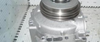
Structurally, a fluid coupling is a connection of two wheels of a specific shape. The drive wheel is bolted to a casing fixed to the shaft. The generator drive pulley hub is attached to it externally. The casing contains another wheel - a driven one, equipped with special blades. A gap is formed between the two wheels, which is the working cavity of the fluid coupling - oil enters here. The driven wheel is also rigidly connected to the shaft on which the fan hub is fixed. The entire structure is installed on the same axis with the crankshaft.
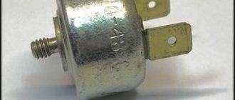
To ensure timely supply of oil to the fluid coupling, a special unit is used - a switch for the KamAZ Euro 2 fluid coupling and other modifications, capable of operating in three positions.
Externally, the switch is a metal case with a temperature sensor located in it. If the temperature of the working fluid (antifreeze, antifreeze) rises to 83-86 degrees. Celsius, a special mass placed in the sensor begins to change its properties and expand, affecting the rod. The consequence of this is the opening of the oil channel and the flow of oil into the working cavity of the fluid coupling. If the coolant temperature decreases, the rod returns to its original position, blocking the oil flow.
The operation of the hydraulic type device is possible in three options: automatic, permanently open or permanently closed. The first option has priority, of course, in the absence of any problems. If malfunctions are detected, it is better to move the flag to the permanently open position and try to replace the unit. But the “permanently closed” position can be useful if the car has to ford through a water obstacle.
Features of fan clutch maintenance
The fan clutch may need to be replaced at any time. Its onset is indicated by characteristic noises, knocking, wear of splines, etc.
Each type of fan clutch has its own maintenance features. In general, the process of dismantling a fluid coupling consists of removing oil from the power unit systems, removing the oil filter, crankcase, drive belts and fan impeller. Then the fastenings of the fluid coupling, drive shaft, driven wheel and shaft are unscrewed and removed.
Kamaz electric coupling sensor
A truck engine produces a lot of heat. To prevent the mechanisms from overheating, it is necessary to use a cooling system. The most important cooling agent is antifreeze, which is “driven” by a special system throughout the entire mechanism that needs cooling. The second option is the natural intake of cool air. Fan operation is considered the most efficient.
Kamaz vehicles have two types of cooling: air and combined. The combined type is also called liquid-air. Both cooling options require a fan. This component of the entire cooling system experiences strong vibrations, heavy loads, and is subject to a serious noise effect. The fan speed may also gradually decrease. To ensure that the mechanism remains in the same mode, a special clutch is installed for the fan. It relieves large dynamic loads, taking part of the “impact” upon itself; accordingly, the presence of a coupling is necessary.
Electrical diagram of the KamAZ 65115 car
It is clear that the more preferable option in terms of convenience and information content is the KamAZ color electrical diagram, in which the color of the cables used in the standard electrical wiring is reflected by the corresponding color of the lines. In addition, this image shows in schematic form all devices, sensors and components operating from the vehicle’s on-board network.
All KamAZ trucks, including the model 65115 in question, are equipped with a number of electrical subsystems. Specifically, the machine utilizes electrical systems that provide the following functions and capabilities.
- Starting the propulsion system.
- Functioning of the heating system, windshield wiper and power supply system.
- Lighting fixtures inside the car interior.
- Lighting, including high and low beam lights, fog lights, side lights, brake lights, turning lights and hazard warning lights.
- The instrument panel, which is one of the main components of the on-board electrical network due to the concentration of most sensors, instruments and devices, including the speedometer, tachometer, fuel gauge and many others. It is the instrument panel that is equipped with various indicators that light up when the lights are turned on, the hand brake is activated, and in other situations, and allow the driver to indirectly assess the condition of certain systems and units.
- Functioning of the anti-theft system and multimedia system.
- The operation of the fuse box, which is responsible for preventing problems in the operation of electrical networks in the event of voltage surges. The mounting block includes a number of fuses that ensure the functionality of all critical electrical systems.
- A control unit responsible for the full functioning of various electrical equipment.
To ensure normal operation of the KamAZ 65115 electrical system, the vehicle's electrical wiring must be in a condition no worse than satisfactory. In addition, the health of a number of electrical system components, including batteries, plays a very important role.
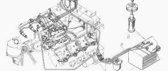
The KamAZ vehicle uses two batteries connected in series, the positive output of which is connected to the starter connector, and the output with a minus sign is connected to the truck body through a switch. The batteries, located in a box located on the frame of the car behind the cab, ensure the functionality of the ignition during engine starting, as well as the ability to operate various electrical equipment when the engine is stopped.
The KamAZ electrical circuit is not capable of functioning normally without such an important link as a generator. It provides power to electrical components and devices when the engine is running. In addition, it is the generator unit that charges the batteries.
How to replace a fluid coupling?
The fluid coupling works for a long time without any intervention. KamAZ-740 can afford this. But sooner or later everything wears out. If this happens and the further efficiency of the cooling system is in question, it is necessary to dismantle the element.
The installation location of the fan drive and fluid coupling significantly complicates the replacement work. First of all, you need to gain access to the engine. In the case of a KamAZ vehicle, this is done by raising the cab. The sequence of work to replace the fluid coupling may look like this:
- drain engine oil;
- remove the attachment belt;
- unscrew the cooling fan;
- remove the oil pan;
- remove the cooling radiator;
- remove the oil cooler;
- remove the oil filter;
- provide access to the front cover of the block by lifting the engine;
- remove the front cover together with the fluid coupling.
After the fluid coupling is removed, the degree of wear and types of defects are revealed. If possible, some elements are replaced. But given the complexity of the operation to replace the coupling, it is recommended to replace the entire assembly. It’s even better and easier to replace the fluid coupling assembly with the front cover of the block.
After the reverse assembly procedure has been performed, it is necessary to check the tightness of the system and then only the functionality of the fluid coupling. When replacing a unit, you must choose an original part and not look for adventures in selecting any analogues.
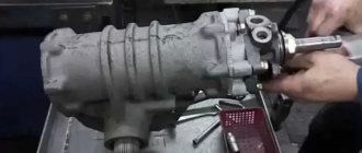
How to disassemble the coupling
- First of all, remove the cooling fan. As a rule, to remove it you need to unscrew 3 or 4 bolts.
- We inspect the coupling.
- Let's dismantle it.
If the coupling is dismountable, then you can repair it:
- To do this, first drain the oil through a special hole.
- Remove the plate that covers the bearing.
- The bearing is removed with a puller. You can make a puller with your own hands, or you can buy one.
- Press in a new bearing.
- They put on a record.
- Pour in gel or oil.
- Attach the fan.
How can you tell if there is enough fluid in the viscous coupling? If, when the engine is stopped, the fan stops abruptly, then there is not enough liquid.
It is recommended to fill the viscous coupling with silicone-based oil. Refilling is done with a syringe.
If there are mechanical failures, then it is not repaired.
Replacing the old one and installing a new viscous coupling is an easy job, even a beginner can do it. After dismantling the device, you need to remove the fan impeller. Install a new coupling. When installing a new coupling, you must tighten the bolts firmly, but without stripping the threads. Then you need to install the fan in place.
Theme Options
Search by topic
Types and functional features
There are several types of couplings: elastic, electromagnetic, friction, hydraulic, viscous couplings. Each variety has its own functional characteristics.
- For example, an elastic one transmits torque using two contacting rubber discs, so when the engine mode changes, the force impact falls on the soft rubber. This type is considered obsolete, so it can only be found on old KamAZ trucks. Modern models have other design solutions. The operation of the coupling is carried out thanks to two disks: the inner diameter of the driver has mounting teeth, which are secured to the shaft, the driven one has threaded bushings for seating the fan.
The friction one has a more modern structure: it is turned on and off by a drive that responds to information from the temperature sensor. Temperature 80 degrees - turn off the fan, 90 degrees - turn on. This type is considered more technologically advanced, so friction clutches can be found on a fairly large number of trucks. By working directly with temperature, the information transmitted to the fan is considered more reliable than the forceful operation of the rubber parts of the mechanism. The system has a driven disk, a drive disk, a pressure disk, a diaphragm spring, and a drive that increases or decreases the air pressure inside the system.
Today, electric fans with electronic control are the most popular. The temperature is regulated by sensors that provide information to the central electronic unit. Modern computerized systems work more smoothly, preventing the liquid from overheating.
Posts 1 page 30 of 154
- Author: Chinese
- Guest
Actually the question is: How to properly check the thermal coupling? Car 65201. The car is constantly heating up. I wash the radiator and cooler every day, but it doesn’t help much. Thermostat OK! Should I leave the thermal coupling, or switch to an electric coupling with forced force? There are not enough forum participants, but suddenly someone had such a problem. Or a link where this is discussed. Thank you in advance.
- Author: Sergey
- Guest
- From: St. Petersburg
- Posts: 1161
- Gender: Male
- Spent on the forum: 1 month 13 days
When the propeller turns on, it makes such a noise that it’s simply impossible not to hear it. It doesn’t work for you.
- Author: Pan
- Moderator
- From: Kaluga
- Posts: 8044
- Gender: Male
- Spent on the forum: 3 months 19 days
I don’t know if I wrote in this thread or not, I didn’t want to start a new topic. Does anyone know, they are now producing motors with an electric fan coupling. I saw this on 43118. The control key in the cockpit is O.P.A. Convenient, compact and no extra troubles with oil. There is simply no such system available for sale. There are all sorts of newfangled fluid couplings, but there is none.
DIY viscous coupling repair
If this device stops working, you must first refill it with gel or special oil.
There are not many specialists who can repair viscous couplings. Sometimes it is cheaper and faster to buy a new device or switch to an electric fan.
To install an electric engine cooling fan, you need the following parts:
- The fan itself is electrically driven.
- Wires with a cross-sectional area of 6 mm2.
- 40 Amp fuse.
- Relay regulator 30 Amp or more.
- A thermal relay, for example, from a Lada car, which is activated when the engine heats up to 87 degrees.
The thermal relay can be glued to the radiator or next to the thermostat on a metal surface.
After this, you need to make a connection diagram, like on VAZ cars. The VAZ electrical circuit for connecting the fan will last about 5 years.
KAMAZ electric coupling activation sensor
Today, automotive technology is widely used in all sectors of modern society. Based on the tasks performed by this equipment, appropriate requirements are imposed on its components and assemblies.
The main unit of any type of automotive technology is the engine. Accordingly, the performance of the engine determines the performance of the machine as a whole. The failure of engine parts is one way or another accompanied by a violation of the normal temperature regime of its operation, which in turn is provided by the engine cooling system.
The most common in modern engines is a closed liquid cooling system, the design of which includes a liquid pump, a cooling jacket, thermostats, a radiator, an expansion tank, a driven fan, blinds (or curtains), a radiator diffuser, connecting pipes and hoses, as well as control measuring instruments.
The fan is an integral part of the cooling system of any modern car engine. It serves to increase the cooling intensity of the liquid in the radiator. The fan can have various drives. The mechanical drive transmits rotation to the fan from the crankshaft through a gear or V-belt drive, as well as through elastic and inelastic couplings. The advantage of this drive is its simplicity. However, a significant disadvantage of this drive is the lack of the ability to briefly turn off the fan to ensure less heat removal from the radiator and, as a consequence, engine overcooling. The solution to this problem is the use of drives whose design provides the ability to turn off and turn on the fan, if necessary, in both automatic and forced modes. These include viscous, hydrodynamic, and electromagnetic couplings. The main disadvantage of viscous and hydrodynamic couplings is the complexity of their design, which results in high cost.
The design of electromagnetic couplings is simpler, which makes them cheaper. It is also possible to use this coupling in conjunction with a mechanical drive. For example, on engines of the KamAZ family, an electromagnetic clutch is installed, shown in Fig. 1. The operation of this clutch is controlled using a thermobimetallic sensor, which, when the temperature of the coolant rises above the operating temperature, closes the electrical circuit, and an electric current is supplied to an electric coil with a metal core, fixedly fixed inside the rotating pulley, resulting in a magnetic field. Under the influence of magnetic forces, the driven disk mounted on the fan hub is attracted to the pulley, as a result of which the fan begins to rotate along with the pulley. The disadvantage of this drive is that if there is no electric current in the circuit, torque will not be transmitted to the fan. This can lead to engine overheating and failure.
Based on this, it is advisable to change the design of this drive in such a way that torque is transmitted to the fan even in the event of an electrical circuit failure.
As a solution to this problem, we propose the design of an electromagnetic coupling, shown in Fig. 2.
The proposed electromagnetic fan drive clutch consists of a pulley, a fixed electromagnetic coil, a bearing, a fan hub, pads with friction linings and spacer springs. Its work is carried out as follows. The pulley receives constant rotation from the engine crankshaft. Through the projections, the pulley engages with friction linings, which, under the action of spacer springs, are pressed tightly against the fan hub. In this case, the fan is set in motion. When rotating, the pads are also subject to centrifugal forces, which increase the pressure of the pads and prevent the fan from slipping.
b
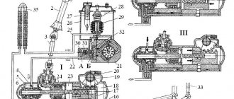
Rice. 1. Electromagnetic clutch of the fan drive: a – friction disc cutout; b – threaded hole of the pulley; 1 – adjusting bolt; 2 – bearing; 3 – fan hub; 4 – pulley mounting bolt; 5 – gasket; 6 – friction disc mounting bolt; 7 – friction disc; 8 – fan; 9 – drive pulley for the generator and liquid pump; 10 – electromagnetic coil; 11 – bolt for fastening the electromagnetic coil; 12 – power take-off shaft; 13 – front crankcase cover; 14 – fan switch sensor; 15 – spring plate
Rice. 2. Electromagnetic clutch of the fan drive: 1 – Fixed electromagnetic coil; 2 – pulley; 3 – bearing; 4 – fan hub; 5 – pads with friction linings; 6 – spacer springs; 7 – pulley protrusions
When the coolant temperature drops below the operating temperature, a thermobimetallic sensor installed in the coolant flow in the cooling jacket closes the electrical circuit. In this case, an electric current enters the electromagnetic coil, resulting in a magnetic field. Under the influence of a magnetic field, the pads overcome the resistance of the spacer springs and centrifugal forces and disengage with the fan hub, while the fan rotation stops and the radiator is not blown.
As the coolant temperature rises above the operating temperature, the thermobimetallic sensor opens the electrical circuit again. In this case, the magnetic field disappears, and the pads are pressed against the hub under the action of spacer springs and centrifugal forces. The fan starts up again.
Thus, with this design, it is possible to use an electromagnetic clutch as a fan drive. In this case, the possibility of stopping the rotation of the fan due to a malfunction of the electrical circuit is excluded. With all this, the proposed coupling retains the geometric dimensions of the original electromagnetic coupling, which will allow their interchangeability. An application for a utility model has been submitted to Rospatent for the proposed design.
Role in the internal combustion engine cooling system
A viscous coupling fan is installed on vehicles with a longitudinal engine (usually all-wheel drive and rear-wheel drive models). With this arrangement, it is most advisable to connect the radiator fan pulley to the water pump pulley. As you know, rotation of the water pump is transmitted by a service belt from the crankshaft pulley.
The disadvantage of this design is that the rotation speed of the fan impeller will always be proportional to the crankshaft speed. Such a device will result in the engine being excessively cooled at high speeds in cold air conditions, which will reduce its efficiency. In addition, the permanent connection of the impeller and the crankshaft pulley will increase mechanical friction losses, which will take away power and increase fuel consumption.
The viscous fan coupling allows you to adjust the rotation speed of the impeller depending on the engine temperature.
Device
The difference in the design of viscous fan couplings for Toyota, BMW, Mercedes, Audi. is minimal, since they are all designed and work according to the same principle.
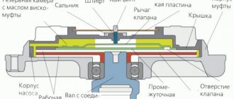
A shaft with a connecting flange is attached to the cooling pump drive, so its rotation speed is always proportional to the crankshaft speed. A drive pulley, in turn, is attached to the shaft, which rotates in the working chamber. The working and backup chambers are separated by plates. The transition between chambers is only possible through inlet valves and return passages. Initially, the backup chamber is filled with special silicone oil. The drive pulley, or disk, as it is also called, has oblique teeth around its circumference, which, when rotated, allow the oil to be expelled back into the reserve chamber. The surface of the drive disks, like the dividing plates, has special ribs that turn the working chamber into a kind of network of labyrinths through which silicone oil circulates.
The coupling housing, to which the fan impeller is attached, is connected to the shaft (viscous coupling rotor) via a conventional ball bearing. The inlet valves are connected to a bimetallic plate, which is located in front of the viscous coupling housing. When heated, the plate expands, which leads to an increase in the flow area of the valves.
Properties of silicone oil
The main feature of silicone fluid used in viscous fan couplings is heat resistance and viscosity stability. As temperature changes, the oil changes its viscosity only slightly.
In the operation of a viscous coupling, silicone oil plays the role of a binding agent, allowing friction to be created between the drive disk and the separating plates connected to the housing. Although there will always be some degree of slip between the housing and the drive pulley, the coefficient of friction generated is sufficient to engage the clutch housing with the drive shaft.
Some sources indicate that with increasing temperature, the oil expands, which provokes viscous engagement of the drive disk with the viscous coupling body. This understanding of the operating principle of a viscous cooling fan coupling is false and most likely arose due to a comparison of the viscous fan coupling with viscous couplings of transfer cases of all-wheel drive vehicles. Viscous differential couplings use a dilatant fluid whose viscosity is highly dependent on the rate of shear strain.
Principle of operation
When the working chamber is not filled with oil, the drive disk rotates freely in the working chamber. A small amount of oil is still present, but the coefficient of adhesion between the drive pulley and the viscous coupling housing is minimal, so as the engine speed increases, the rotation speed of the impeller does not increase.
The process of warming up the engine and increasing the temperature of the antifreeze in the radiator is accompanied by heating of the bimetallic plate. When heated, the plate expands, which leads to the opening of the inlet valve and an increase in the amount of working fluid penetrating from the reserve into the working chamber. The friction that occurs between the drive disk and the separating plates leads to an increase in the speed of rotation of the housing and the fan impeller.
When the engine needs maximum cooling, the bimetallic strip is bent to provide maximum flow area to the intake valves. In this case, the difference in the rotation speed of the shaft and the viscous coupling housing is minimal, so an increase in the crankshaft speed leads to an almost equivalent increase in the rotation speed of the fan impeller.
A decrease in the temperature of the incoming air leads to a gradual return of the bimetallic plate to its original position. Accordingly, the flow area of the intake valves decreases, the liquid is distilled into the reserve cavity. A decrease in the adhesion coefficient leads to an increase in the difference in the rotation speed of the viscous coupling drive shaft and the housing - the fan impeller slows down.