Category: KAMAZ
- Description of KamAZ brakes
- Brake Accessories
- Emergency warning and control signals KamAZ
- The principle of operation of the KamAZ brake
- Brake drive
- Adjusting the KamAZ brake system
- Partial adjustment of the KamAZ brake
- Complete adjustment of KamAZ brakes
The KamAZ brake system is a guarantor that can, if necessary, stop the vehicle in time without causing negative consequences. The KamAZ vehicle is a large and heavy vehicle. Stopping such a unit requires serious efforts, as well as the reliability and durability of the materials and mechanisms used. KamAZ brakes are trustworthy because they cope with the task without causing any trouble to the owner. Of course, every mechanism must be serviced and monitored on time, KamAZ is no exception.
KamAZ 55111:
Description of KamAZ brakes
Each car produced by the Kama plant has four types of brake equipment on board.
- Main brake;
- Reserve brake;
- Stop brake;
- Auxiliary brake.
These types of equipment cope with the task without the need for mutual assistance, and as a result, the indicator of the work performed reaches efficiency. If automatic braking is accompanied by the release of air masses from the profile, the machine has an emergency release mechanism. The principle of using the device is to resume operation. Monitoring and signaling sensors for status and performance are also installed.
The main brake reduces the KamAZ speed limit, down to a complete stop. Vehicle stopping devices are located on six wheels of the vehicle. The operating principle of the drive is based on air under pressure. The unit is equipped with two circuits, the action of which extends to the bow and stern axles separately.
Activation of the main stopping mechanism occurs through a foot lever, which transmits the force to the brake valve. Brake chambers are converters of air pressure force into movement of brake pads.
The backup motion damper reduces the speed limit and stops the car when the main brakes fail or the function is not fully performed by the main device.
The stopping system forces the vehicle to remain stationary on a level surface, without intervention from the pilot. Feature of the stopping mechanism, paired with a backup brake. The activation is actual after the lever is moved to the required position.
KamAZ parking and auxiliary brakes:
From the above it is clear that at KamAZ the stopping methods used are the same for the main, backup and stopping motion dampers based on the stern. As for the backup and stopping dampers, they have the same pneumatic propulsion device.
An additional motion damper works to reduce the degree of heating of the equipment, the main speed reduction device. This includes the power plant muffler, which switches the exhaust manifold, and turns off the fuel mixture input.
Emergency unlocking wedges the pads if they worked automatically and stopped the car. The emergency stop drive is double, activated both by pneumatics and mechanical screws. This was done in order to unlock energy batteries in automatic or manual mode.
BRAKE SYSTEM (brake diagrams)
BRAKE SYSTEM.
KamAZ vehicles and road trains are equipped with four autonomous braking systems: service, spare, parking and auxiliary. Although these systems share common elements, they operate independently and provide high braking performance in all operating conditions. In addition, the vehicle is equipped with an emergency brake release drive, which makes it possible to resume the movement of the vehicle (road train) when it is automatically braked due to a compressed air leak, an alarm and monitoring devices that allow monitoring the operation of the pneumatic drive.
The brake system of modernized KAMAZ vehicles, unlike production vehicles, contains:
— single-cylinder compressor with a capacity of 380 l/min at a back pressure of 0.7 MPa (7 kgf/cm2) and engine speed of 2200 rpm;
— the service brakes are controlled by a two-section brake valve with a suspended pedal installed on the front panel of the cabin;
— instead of a block of safety valves, a four-circuit safety valve is used;
— a cooler is installed to cool the compressed air;
— an accelerator valve in the line of circuit II of the brake system to reduce the response time of the rear bogie brakes;
— proportional valve (only for KA-MAZ-65115);
— instead of Palm type connection heads, automatic heads are installed.
The working brake system is designed to reduce the speed of the vehicle or stop it completely. The brake mechanisms of the service brake system are installed on all six wheels of the vehicle. The drive of the service brake system is a dual-circuit pneumatic system; it operates separately the brake mechanisms of the front axle and the rear bogie of the vehicle. The drive is controlled by a foot pedal, mechanically connected to the brake valve. The actuators of the service brake system drive are the brake chambers.
The spare brake system is designed to smoothly reduce the speed or stop a moving vehicle in the event of a complete or partial failure of the working system.
The parking brake system provides braking of a stationary vehicle on a horizontal section, as well as on a slope and in the absence of a driver. The parking brake system on KamAZ vehicles is designed as a single unit with the spare one, and to activate it, the hand valve handle should be set to the extreme (upper) fixed position.
Thus, in KamAZ vehicles, the brake mechanisms of the rear bogie are common to the working, spare and parking brake systems, and the latter two also have a common pneumatic drive.
The brake auxiliary system of a vehicle serves to reduce the load and temperature of the brake mechanisms of the service brake system. The auxiliary braking system on KamAZ vehicles is an engine retarder, when activated, the engine exhaust pipes are blocked and the fuel supply is turned off.
The emergency brake release system is designed to release spring energy accumulators when they are automatically activated and the vehicle stops due to a compressed air leak in the drive. The drive of the emergency brake release system is duplicated: in addition to the pneumatic drive, there are emergency brake release screws in each of the four spring energy accumulators, which allows the latter to be released mechanically.
The alarm and control system consists of two parts:
1. Light and acoustic signaling about the operation of brake systems and their drives. At various points of the pneumatic drive, pneumatic-electric sensors are built in, which, when any braking system, except the auxiliary one, is in operation, closes the circuits of the electric brake light lamps. Pressure drop sensors are installed in the drive receivers and, if there is insufficient pressure in the latter, they close the circuits of the signal lamps located on the vehicle's instrument panel, as well as the sound signal (buzzer) circuit.
2. Valves of control terminals, with the help of which the technical condition of the pneumatic brake drive is diagnosed, as well as (if necessary) the selection of compressed air. KamAZ tractor-trailers are also equipped with a set of pneumatic devices for actuating the brake mechanisms of a trailer (semi-trailer) with a single-wire and double-wire drive. The presence of such a drive on tractors ensures their aggregation with any trailers (semi-trailers) that have a pneumatic drive of the brake mechanisms.
Below are the main technical data of the brake systems (Table 45).
| Table45 | |||||||||
| Automobile model | 5320 5410 | 53212 5321354112 | 53215 54115 | 55111 53229 | 65115 | 43101 | 43114 43115 4311844108 | 4326 | 53228 642665111 |
| Length of the adjusting lever, mm: - front axle | 125 | 150 | 125 | 150 | 125 | 150 | |||
| - rear axle | 125150 | 125 | |||||||
| Stroke of brake chamber rods, mm: - front axle | 20-30 | 25-35 | 20-30 | 25-35 | 20-30 | 25-35 | |||
| - rear trolley | 20-30 125-35 | 20-30 | 20-30 | ||||||
| Type of brake chambers: - front axle | 24 | 24 | 30 | 24 | 30 | 24 | 24 30 | ||
| - rear trolley | 20/20 | 24/24 | |||||||
| Drum diameter, mm | 400 | ||||||||
| Width of pads, mm | 140 | ||||||||
| Total area of pads, mm2 | 6300 | 4200 | 6300 | ||||||
| Brake force regulator lever length, mm | 110 | 90 | No regulator | 90 | 138 | 90 | |||
| Static deflection of rear suspension, mm | 40 | 35 | 35 | 50 | 35 | ||||
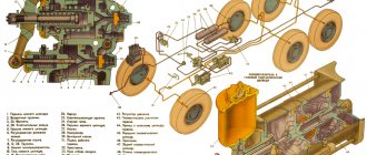
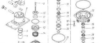
Rice. 285. Brake mechanism: 1 - pad axis; 2 - caliper; 3 — shield; 4 - axle nut; 5 — pad axle lining; 6 — block axis pin; 7 — brake pad; 8 - spring; 9 — friction lining; 10-bracket for expanding fist; 11 — roller axis; 12 — expansion fist; 13 - roller; 14 — adjustment lever
The brake mechanisms (Fig. 285) are installed on all six wheels of the car, the main unit of the brake mechanism is mounted on caliper 2, rigidly connected to the axle flange. Two brake pads 7 with friction linings 9 attached to them, made along a crescent-shaped profile in accordance with the nature of their wear, rest freely on the eccentrics of the axles 1, fixed in the caliper. The axes of the shoes with eccentric supporting surfaces allow the shoes to be correctly centered relative to the brake drum when assembling the brake mechanisms. The brake drum is attached to the wheel hub with five bolts.
When braking, the pads are moved apart by an S-shaped fist 12 and pressed against the inner surface of the drum. Between the expanding fist 12 and the pads 7, rollers 13 are installed, which reduce friction and improve braking efficiency. The pads are returned to the braked state by four release springs 8.
The expanding fist 12 rotates in the bracket 10, bolted to the caliper. The brake chamber is installed on this bracket. At the end of the expansion cam shaft there is an adjusting lever 14 of the worm type, connected to the brake chamber rod using a fork and a pin. A shield bolted to the caliper protects the brake mechanism from dirt.
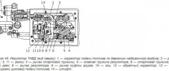
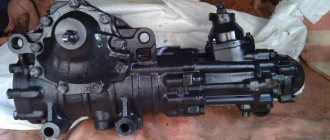
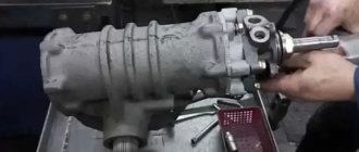
Rice. 286. Adjustment lever: 1- cover; 2 - rivet; 3 - gear wheel; 4 - plug; 5 - worm; 6 — body; 7 - bushing; 8 — locking bolt; 9 — clamp spring; 10 — retainer ball; 11 - worm axis; 12 - oiler
The adjusting lever is designed to reduce the gap between the pads and the brake drum, which increases due to wear of the friction linings. The arrangement of the adjustment lever is shown in Fig. 286. The adjusting lever has a steel body 6 with a bushing 7. The body contains a worm gear 3 with splined holes for installation on the expansion fist and a worm 5 with an axis 11 pressed into it. To fix the worm axis there is a locking device, the ball 10 of which enters the holes on the worm axis 11 under the action of the spring 9, resting against the locking bolt 8. The gear wheel is kept from falling out by covers 1 attached to the lever body 6. When the axle is turned (by the square end), the worm turns wheel 3, and the expansion fist turns with it, pushing the pads apart and reducing the gap between the pads and the brake drum. When braking, the adjustment lever is turned by the brake chamber rod.
Before adjusting the gap, lock bolt 8 must be loosened one or two turns; after adjustment, tighten the bolt securely.
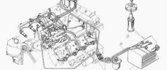
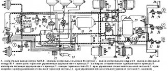
Drive of brake mechanisms. Schematic diagrams of the drive are shown in Fig. 287-292.
Rice. 287. Pneumatic drive of car brake mechanisms mod. 5320: A - control output of circuit IV; B, E - valves of control terminals of the third circuit; C - control output of circuit I; D - control output of circuit II; N — brake control line of a two-wire drive; P — connecting line of a single-wire drive; R - main supply line for a two-wire drive; 1 — brake chambers type 24; 2 — parking brake system control valve; 3 — emergency brake release valve for the parking brake system; 4 — auxiliary brake system control valve; 5 — two-pointer pressure gauge; 6 — control lamps and sound signaling device; 7 — control valve; 8 — pressure limitation valve; 9 - compressor; 10 — pneumatic cylinder for driving the engine stop lever; 11 — pressure regulator; 12 - anti-freeze fuse; 13 — double safety valve; 14 - sensor for turning on the solenoid valve of the trailer brake mechanism; 15 — rechargeable batteries; 16 — two-section brake valve; 17 — triple safety valve; 18 — pressure drop sensor in the receiver; 19 — condensate drain valves; 20 — condensing receiver; 21 — air bleed valve; 22 — receivers of circuit II; 23 — pneumatic cylinder for the auxiliary brake system flap drive; 24, 25 — receivers of circuits I and III; 26 — brake chambers of type 20x20; 27 — sensor for turning on the warning lamp of the parking brake system; 28 — energy accumulators; 29 — accelerator valve; 30 — automatic brake force regulator; 31 — trailer brake control valve with a two-wire drive; 32 — two-line valve; 33 — sensor for turning on the brake signal; 34 — trailer brake control valve with a single-wire drive; 35 — single safety valve; 36 — rear lights; 37 — isolation valves; 38, 39 — connection heads type A and type “Palm”
Rice. 288. Diagram of the pneumatic drive of the brake mechanisms of KamAZ-53229, -65115, -54115, -43253: 1 - water separator; 2 - compressor; 3 - cooler; 4 - four-circuit safety valve; 5 - automatic brake force regulator; 6 — pressure regulator; 7 - brake signal switch; 8 - brake valve; 9 — pneumatic cylinders for the flap drive of the auxiliary brake system mechanism; 10 — parking brake system control valve; 11 - proportional valve; 12 - pneumatic cylinder for driving the engine stop lever; 13 — auxiliary brake system control valve; 14 - pressure gauge; 15- brake chambers type 30/30; 16 - receiver circuit 1Y; 17 — receivers of circuit 11; 18 — condensate drain valve; 19 — brake chambers type 20/20; 20.24 - accelerator valves; 21 - two-line bypass valve; 26 switch for the parking brake system warning lamp; 23 — receiver of circuit III; 25 — receiver of circuit I; 26 — switch for warning lamp for air pressure drop in circuit III; 27 — emergency brake release valve
Rice. 289. Diagram of the pneumatic drive of the brake mechanisms of KamAZ-4326 vehicles: 1 - type 24 brake chambers; 2 (A, B, C) - control terminals; 3 — pneumoelectric switch of the trailer solenoid valve; 4 — auxiliary brake system control valve; 5 — two-pointer pressure gauge; 6 - compressor; 7 - pneumatic cylinder for driving the engine stop lever; 8 - water separator; 9 — pressure regulator; 11 — two-line bypass valve; 12-4 circuit safety valve; 13 — parking brake system control valve; 14 - heat exchanger; 15 — two-section brake valve; 17 — pneumatic cylinders for driving the flaps of the auxiliary brake system mechanism; 18 — receiver of circuit I; 19 — consumer receiver; 20 — pressure drop alarm switch; 21 — receiver of circuit III; 22 — receivers of circuit II; 23 — condensate drain valve; 24 — brake chambers of type 20/20 with spring energy accumulators; 25, 28 — accelerator valves; 26 — control valve for trailer brake systems with a two-wire drive; 27 — parking brake system warning switch; 29 — control valve for trailer brake systems with a single-wire drive; 30 - automatic connecting heads; 31 — connection head type A; R - to the supply line of the two-wire drive; P - to the connecting line of the single-wire drive; N - to the control line of the two-wire drive; 31 - pressure drop sensor in the primary circuit receivers; 32 - pressure drop sensor in receivers of the 2nd circuit; 33-brake signal sensor; 34-crane emergency brake release
| Rice. 290. Diagram of the pneumatic drive of the brake mechanisms of KamAZ-43118, -65111 vehicles |
Rice. 291 . Diagram of the pneumatic drive of the brake mechanisms of KamAZ-43101, 43114 vehicles: 1 - type 24 brake chambers; 2 (A, B, C) - control terminals; 3 — pneumoelectric switch of the trailer solenoid valve; 4 — auxiliary brake system control valve; 5 — two-pointer pressure gauge; 6 - compressor; 7 — pneumatic cylinder for driving the engine stop lever; 8 - water separator; 9 — pressure regulator; 11 - two-line bypass valve; 12-4 circuit safety valve; 13 — parking brake system control valve; 14 - heat exchanger; 15 — two-section brake valve; 17 — pneumatic cylinders for driving the flaps of the auxiliary brake system mechanism; 18 — receiver of circuit I; 19 — consumer receiver; 20 - pressure drop alarm switch; 21 — receiver of circuit III; 22 — receivers of circuit II; 23 — condensate drain valve; 24 — brake chambers of type 20/20 with spring energy accumulators; 25, 28 — accelerator valves; 26 — control valve for trailer brake systems with a two-wire drive; 27 — parking brake system warning switch; 29 — control valve for trailer brake systems with a single-wire drive; 30 - automatic connection heads; 31 — connection head type A; R - to the supply line of the two-wire drive; P - to the connecting line of the single-wire drive; N - to the control line of the two-wire drive; 31 - pressure drop sensor in the primary circuit receivers; 32 - pressure drop sensor in receivers of the 2nd circuit; 33-brake signal sensor; 34-crane emergency brake release
| Rice. 292. Diagram of the pneumatic drive of the brake mechanisms of KamAZ-53228 vehicles |
The source of compressed air in the drive is compressor 9. The compressor, pressure regulator 11, fuse 12 against condensate freezing, condensation receiver 20 constitute the supply part of the drive, from which purified compressed air at a given pressure is supplied in the required quantity to the remaining parts of the pneumatic brake drive and to other consumers of compressed air. The pneumatic brake drive is divided into autonomous circuits, separated from each other by safety valves. Each circuit operates independently of other circuits, including when faults occur. The pneumatic brake actuator consists of five circuits separated by one double and one triple safety valve.
Circuit I of the drive of the working brake mechanisms of the front axle consists of a part of a triple safety valve 17; receiver 24 with a capacity of 20 liters with a condensate drain valve and pressure drop sensor 18 in the receiver, part of a two-pointer pressure gauge 5; lower section of a two-section brake valve 16; valve 7 control terminal (C); pressure limit valve 8; two brake chambers 1; brake mechanisms of the front axle of the tractor; pipelines and hoses between these devices.
In addition, the circuit includes a pipeline from the lower section of the brake valve 16 to the valve 81 for controlling the brake systems of a trailer with a two-wire drive.
Circuit II of the drive of the working brake mechanisms of the rear bogie consists of a part of the triple safety valve 17; 22 receivers with a total capacity of 40 liters with condensate drain valves 19 and pressure drop sensor 18 in the receiver; parts of a two-pointer pressure gauge 5; the upper section of the two-section brake valve 16; control output valve (D) of the automatic brake force regulator 30 with an elastic element; four brake chambers 26; brake mechanisms of the rear bogie (intermediate and rear axles); pipelines and hoses between these devices. The circuit also includes a pipeline from the upper section of the brake valve 16 to the brake control valve 31 with a two-wire drive.
Circuit III of the drive mechanisms of the spare and parking brake systems, as well as the combined drive of the brake mechanisms of the trailer (semi-trailer), consists of a part of the double safety valve 13; two receivers 25 with a total capacity of 40 liters with a condensate drain valve 19 and a pressure drop sensor 18 in the receivers; two valves 7 control output (B and E) of manual brake valve 2; accelerator valve 29; parts of a two-line bypass valve 32; four spring energy accumulators 28 brake chambers; sensor 27 for pressure drop in the line of spring energy accumulators; valve 31 for controlling the brake mechanisms of a trailer with a two-wire drive; single safety valve 35; valve 34 for controlling the brake mechanisms of a trailer with a single-wire drive; three isolation valves 37 three connection heads; heads 38 type A for a single-wire drive of the trailer brakes and two heads 39 of the “Palm” type for a two-wire drive of the trailer brakes; pneumoelectric brake light sensor 33, pipelines and hoses between these devices. It should be noted that the pneumoelectric sensor 33 in the circuit is installed in such a way that it ensures that the “brake light” lamps turn on when the car is braking not only by the spare (parking) brake system, but also by the working one, and also in the event of failure of one of the circuits of the latter .
Circuit IV of the drive of the auxiliary brake system and other consumers does not have its own receiver and consists of a part of a double safety valve 13; pneumatic valve 4; two cylinders 23 damper drives; cylinder 10 of the engine stop lever drive; pneumoelectric sensor 14; pipelines and hoses between these devices.
From circuit IV of the drive mechanisms of the auxiliary brake system, compressed air is supplied to additional (non-brake) consumers; pneumatic signal, pneumohydraulic clutch booster, control of transmission units, etc.
Circuit V of the emergency brake release drive does not have its own receiver and actuators. It consists of a triple safety valve part 17; pneumatic valve 4; parts of a two-line bypass valve 32; pipelines and hoses connecting the devices.
The pneumatic brake drives of the tractor and trailer connect three lines: the line of the single-wire drive, the supply and control (brake) lines of the two-wire drive. On truck tractors, connecting heads 38 and 39 are located at the ends of three flexible hoses of the said lines, mounted on a support rod. On flatbed vehicles, heads 38 and 39 are mounted on the rear cross member of the frame.
To improve moisture separation in the supply part of the brake drive of cars mod. 53212, 53213 in the compressor - pressure regulator section, there is an additional moisture separator installed on the first cross member of the car in the intensive airflow zone.
For the same purpose, on all KamAZ vehicle models, a condensation receiver with a capacity of 20 liters is provided in the anti-freeze section - protective valves. The 55111 dump truck does not have trailer brake control equipment, disconnect valves, or connecting heads.
To monitor the operation of the pneumatic brake drive and timely signal about its condition and emerging malfunctions in the cockpit, there are five warning lights on the instrument panel, a two-pointer pressure gauge indicating the compressed air pressure in the receivers of two circuits (I and II) of the pneumatic drive of the service brake system, and a buzzer , signaling an emergency drop in compressed air pressure in the receivers of any brake circuit.
Rice. 293. Mechanism of the auxiliary brake system: 1 - housing; 2 — rotary lever; 3 - damper; 4 - shaft
Mechanism of the auxiliary brake system (Fig. 293). In the exhaust pipes of the muffler there is a housing 1 and a damper 3 mounted on a shaft 4. A rotary lever 2 connected to the pneumatic cylinder rod is also attached to the damper shaft. Lever 2 and the associated damper 3 have two positions. The internal cavity of the body is spherical. When the auxiliary brake system is turned off, damper 3 is installed along the flow of exhaust gases, and when turned on, it is perpendicular to the flow, creating a certain back pressure in the exhaust manifolds. At the same time, the fuel supply is stopped. The engine starts operating in compressor mode.
Brake Accessories
To improve the brakes on KamAZ, late-release vehicles are equipped with additional equipment that distinguishes the products from the series units:
- Pressure booster, single-cylinder, produces 380 liters per minute;
- The brake valve is two-sectional and controls the main brake via a foot lever;
- Safety, four-circuit regulator;
- A mechanism that reduces the temperature of air under pressure;
- Valve accelerator, reduces rear brake reaction time;
- Valve for proportional change of input value (KAMAZ-65115);
- Connecting adapters.
KamAZ accelerator valve:
Handbrake on KamAZ - Design and connection diagram
The parking brake is an integral part of any vehicle. Special requirements for its reliability are put forward in heavy trucks, which include KamAZ. In this machine, it consists of brake mechanisms and a pneumatic drive, reinforced by energy accumulators. The handbrake on KamAZ is designed to effectively hold massive equipment on flat areas, slopes and inclines, preventing the risk of its unauthorized movement.
Emergency warning and control signals KamAZ
- Indication (visual and audio).
The indication works thanks to sensors located around the perimeter of the system. The indicators are triggered by the operation of the systems (with the exception of auxiliary ones), the contacts initiate the signal lamps to work. Meters that monitor the pressure level are located in containers. Low pressure initiates a short circuit, as a result, the signal lamps on the vehicle's dashboard light up, and an acoustic warning is heard.
- Bypass control devices.
Purpose: to monitor and diagnose the pneumatic drive, if necessary, to bleed off excess air. KamAZ-5410, etc. use actuating devices that brake trailed equipment. Devices for maintaining pressure at the required level make it possible to combine a machine and a hitch equipped with brake pneumatics.
KamAZ 5410:
Performance indicators of KamAZ brakes:
| Parameter | Parameter data |
| Brake type | Drums |
| Drum cross-section, m. | 0,4 |
| Size of applied material, m | 0,14 |
| Area of applied material, m2 | 6,3 |
| Adjustment rod size, m: | |
| Wheelset, nose (5320, 55102), m | 0,125 |
| Wheelset (middle and rear), m | |
| Cars: 5320, 55102 | 0,125 |
| Cars: 65115(dump truck) | 0,150 |
| Rod movement, m: | |
| Wheelset, nose (5320, 5410, 55102, 5511) | 0,02-0,03 |
| Wheelset (middle, rear), m | |
| Cars: 5320, 5410, 55102 | 0,02-0,03 |
| Car: 54122 | 0,025-0,035 |
| Cameras | nose 0.024, middle and back 0.020/0.020 |
| Pressure boosting device | 2-cylinder (piston) |
| Chamber: stroke, section, m | 0.06x0.038 |
| Air, flow, liters per minute | 220 |
| Action | Gear |
| Driven/Driven Gear Ratio | 0,94 |
| Cylinders: | |
| Total, pieces | 6 |
| Volume, liters | 120 |
| Freeze guard, volume, ml | 200 / 1000 |
| Release, resistance kgf/cm2 | 1,7-1,9 |
External and internal lighting system KamAZ-43118
In addition to external lighting, this system is also responsible for lighting inside the vehicle’s cabin. It includes the following devices:
- headlights;
- fog lights;
- front lights;
- rear lights;
- engine compartment lamp;
- lamp for lighting the glove compartment and bed;
- instrument lighting lamp;
- cabin lighting lamp;
- portable lamp.
It has the following scheme:
- right fog lamp
- left fog lamp;
- right headlight
- glove box lamp;
- lamp switch;
- road train lights;
- road train light switch;
- heater motor relay;
- left cockpit light;
- right cockpit light;
- left headlight;
- fog light switch;
- brake signal relay;
- trailer solenoid valve switch;
- rear right lamp
- rear left lamp;
- front right lamp
- front left lamp;
- combination light switch;
- fuse 13.3722 (7.5 A);
- fuse PR 310 (10 A);
- instrument lighting switch;
- engine compartment lamp;
- hazard warning light switch;
- portable lamp socket;
- seven-pin socket;
- oil pressure indicator;
- fuel level indicator;
- speedometer;
- tachometer;
- coolant temperature gauge;
- ammeter;
- pressure gauge;
I. to the instrument and starter switch
All devices, except for the glove compartment light, are connected using a single-wire circuit. As for the glove box lighting lamp, its negative contact is connected to the fuse block.
As for the low and high beams (numbers 3,11), dimensions, fog lights (1,2), they are turned on and off by a combination switch (19) connected through an ammeter.
To protect low beam headlights, as well as fog lights, from short circuits, they are powered through PR310 thermobimetallic fuses. High beams have their own fuses.
The size circuits and instrument lighting lamps are also protected from short circuits by thermobimetallic fuses of type 13.3722.
The principle of operation of the KamAZ brake
To understand what the brake system of KamAZ 65115 and other modifications is, let’s consider the functioning of the stopping unit. The part is equipped with all car wheels (43118, 43114, etc.). The mechanism has a similar operating principle, regardless of the configuration.
KamAZ braking mechanism:
The braking mechanism is mounted and assembled on a caliper (2), the end part is flat in shape with holes for the wheel mounting bolts. Two brake mechanisms (7) with a special material that improves braking (9) are fixed with eccentrics (1). A form of brake material with a specific contour that promotes uniform abrasion. The pins correctly position the brake devices in relation to the drum, which is secured to the hub with five bolts.
Warning light circuit diagram
This system controls the rear brakes and turn signals. It serves to notify other road users about the maneuvers the truck is making. The general diagram of this system is shown in the figure below:
The numbers on the diagram indicate:
- left lamp;
- right lamp;
- turn signal and hazard warning relay;
- fuse PR 119 (6 A);
- light switch;
- fuse 13.3722 (7.5 A);
- fuse PR 310 (10 A);
- hazard warning light switch;
- turn signal right
- left turn indicator;
- rear left lamp
- rear right lamp;
- brake light switch;
- trailer solenoid valve switch;
- brake signal relay;
- sound signal (buzzer);
- 18, 19 — switches for pressure drop alarms in the brake air drive receivers;
- parking brake warning switch;
- relay-interrupter for the parking brake system activation indicator;
- reverse light switch;
- reversing light;
- trailer socket 24 V;
- center differential lock warning switch;
- 27, 28 — signaling units;
- oil filter clogged warning switch;
I. to the instrument and starter switch;
II. to the coolant temperature gauge;
This scheme includes the following subsystems:
- Hazard warning system;
- Brake (stop) indicators;
- Direction indicators
- Indicator lamps for turning on the direction indicators of the vehicle and trailer;
- Center differential lock indicator lamps,
- Parking brake system;
- Drops in air pressure in the pneumatic drive circuits of brake mechanisms;
- Warning lamp blocks,
In addition, the system includes a variety of switches and relays.
Brief explanations of the diagram. Under the number 8 hides the well-known “emergency warning light”. That is, this switch turns on all the direction indicators at once.
The turn signals themselves, in normal mode, are turned on by a combination light switch, marked in the diagram with the number 5. Their intermittent lighting is provided by a special relay (3).
The driver observes the operation of the direction indicators thanks to the signal lamps (26), while the vehicle and the trailer have different signal lamps.
Brake drive
Modifications of KamAZ vehicles are structurally different in speed reduction mechanisms.
Brake system KamAZ 5320 diagram:
Brake system KamAZ 43118 diagram:
The circuit requiring the supply of air under pressure contains: a pressure increase device (9), a pressure reducer (11), a protective element (12), a cylinder (20). From the circuit, pressurized air is transported in the required dose to users. The air damping drive is divided into independent circuits, protected among themselves by means of valves. Air braking drive with five circuits: divided by double and triple regulator.
The first circuit contains: a regulator (17), a cylinder (24) with a means of measuring pressure drops (18), a pressure measuring device with two arrows (5), a lower sector of the brake valve (16), a device for opening and closing the 7th terminal (C); pressure limiting devices 8; cameras 1 (2 pieces); tractor nose wheelbase brakes, pipes.
The second circuit of the aft wheelbase contains: a regulator (17), a cylinder (22) with a valve (19) and a means for measuring pressure reduction (18), means for measuring pressure with two arrows (5), the upper part of the brake valve with two sections (16) , control bypass device (D), damping force regulator, automatic (30), cameras (26) in the amount of four pieces.
KamAZ 43118 - technical characteristics
KamAZ-43118 is an all-wheel drive truck with a 6 × 6 wheel arrangement. This vehicle, with its high cross-country ability, has become simply irreplaceable in hard-to-reach areas of Russia. Also, having a lifting capacity of 10 tons, the machine became the basis for a large number of various special equipment and, above all, truck cranes.
KamAZ-43118 has the following overall dimensions (in millimeters):
- Length – 8580;
- Width – 2500;
- Height – 3455;
- Ground clearance – 385;
- Wheelbase – 3960+1320.
The vehicle is equipped with a KamAZ-740.30-260 diesel engine that meets Euro-2 environmental standards. This power unit is made according to the V8 formula. It has a displacement of 10.85 liters, is equipped with a turbocharger and develops a power of 260 hp. With.
Partial adjustment of the KamAZ brake
Partial adjustment of the brakes on KamAZ is carried out as necessary. The purpose of the adjustments is to achieve the desired distance from the surface of the lining to the drum.
The primary sign signaling the time to adjust the settings of KamAZ mechanisms is the size of the outgoing levers of the brake chambers. The value considered to be the norm for pressure on the foot lever is 20 millimeters.
The desired size is set using the worm of the adjustment lever. Manipulations - on a cold mechanism, the stop brake is moved to the “off” position, the fixing bolt is unscrewed 2-3 turns, then tightened again. The output value of the chamber rods on the wheel sets is set the same, otherwise an unequal force will occur during braking.
Adjusting the KamAZ brake:
Instrumentation system
As you might guess from the name, this system is designed to service various instrumentation, indicators and sensors. Instruments are located on the dashboard of the car, and sensors are located in its various components and mechanisms.
The electrical diagram of this system is as follows:
The numbers on the diagram indicate:
- fuel level indicator;
- fuel level sensor;
- fuse 13.3722 (7.5 A);
- coolant temperature indicator sensor;
- coolant overheat sensor;
- emergency oil pressure sensor;
- oil pressure indicator sensor;
- oil pressure indicator;
- 11 — blocks of warning lamps;
- coolant temperature gauge;
- generator;
- tachometer;
- speedometer;
- speedometer sensor;
I. to the instrument and starter switch
Complete adjustment of KamAZ brakes
Before applying the brakes on a KamAZ, the device is dismantled and rebuilt. Worn parts are replaced. Using eyeliner ensures correct installation of the block in relation to the drum. The adjustment is performed using the eccentric rods of the adjustment lever.
The procedure is performed when the distance from the lining to the drum is 0.2-0.4 millimeters. The measurement is made with a plate, control points: the top and bottom of the pad, the value is thirty millimeters from the edge of the pad. At the same time, it is controlled that the plate, 0.1 millimeter in size, does not move freely across its width.
Power supply system for KamAZ-43118 vehicle
This system, perhaps, can be considered the main one in the car; thanks to this system, the truck is supplied with electricity when the power unit is running. The general diagram of the power supply system is presented below:
In the figure the numbers indicate:
- generator excitation winding cut-off relay;
- generator;
- fuse box;
- starter relay;
- starter;
- rechargeable batteries;
- mains switch;
- button for remote battery disconnect switch;
- heater motor relay;
- ammeter;
- fuses 13.3722 (7.5 A);
- fuse PR310 (10 A);
- instrument and starter switch;
Brief explanations of the diagram:
The energy sources for this system are a generator (2) and two batteries connected in series (6). The negative terminal of the batteries, as in all cars, is connected to the housing. But, unlike passenger cars, on KamAZ it is connected through a special ground switch (7), which has a remote control.
Number 1 in the diagram shows a relay for disconnecting the generator excitation winding. This relay must break the circuit when the electric torch device (EFD), which is responsible for starting the engine in the cold season, is operating.
When the engine is running and the ignition is on (the ignition unit is indicated in the diagram as number 13), the circuit leading to the remote battery mass switch button (8) is opened. This is done so that the engine does not spontaneously turn off accidentally or as a result of a malfunction.
Let's look at the light signaling circuit next: