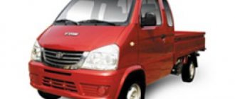
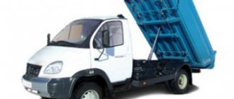
GAZ-3307 is a 4th generation domestic truck, production of which began at the Gorky Automobile Plant. The launch of production of an onboard car with a carburetor engine began in 1989. The production of the truck was almost completed in 1994.
The truck updated the line of cars after the old GAZ-53, which structurally and morally required updating. It was necessary to update the technical parameters and update the appearance of the car.
History of creation
The debut model of the new car left the factory already in 1989, and by the end of the same year they were able to establish serial production of this dump truck. A little later, this vehicle was replaced by another GAZ-3309 truck, on which a diesel power unit was installed.
However, when 2008 arrived, the 3307 was able to receive a brand new carburetor engine with increased power and began production again until 2012. In general, the truck started quite successfully, but almost immediately lost popularity. Following the collapse of the Union of Soviet Socialist Republics, the car noticeably dropped in demand, and its large-scale production at the plant was discontinued.
The Gorky Automobile Plant produces specialized modifications for government agencies. Before the 3307 model, there was a GAZ-53 truck on the market. By the end of the 1980s, such a car was very outdated and needed improvement.
This prompted the designers to start designing a completely new car. The machine was adapted to operate on hard road surfaces. “Lawn” belonged to the 4th generation of GAZ cars. It also includes trucks GAZ-3309, GAZ-3306 and GAZ-4301.
One of the goals that the design staff adhered to during the design of the machine was full-scale synchronization of the main elements and components with previous models. As a result, the car received many parts from the 53rd Lawn.
Thanks to this solution, it was possible to facilitate machine maintenance and reduce production costs. Therefore, Lawn 3307 was able to surpass the 53rd model in numerous characteristics. It was decided to retain the hood layout of the truck.
The models were distinguished by the presence of an improved cabin and a new tail. The salon began to have an abundance of free space, and it was possible to add ventilation and heating. Small changes could also affect the power plant. At the plant in Gorky, the 3307 was planned as a transitional option, which could later be replaced by diesel variations with increased economic characteristics.
A little later, the plant began producing power units that ran on diesel fuel. The production of carburetor versions of the Lawn 3307 was completely stopped with the beginning of the new decade of the 1990s.
Variations with diesel engines also began to lose popularity every year, since their production was no longer profitable. Today, the Gorky Automobile Enterprise can only offer truck configurations with gasoline power units (production is carried out only on order).
Despite the fact that the basis for the "Lawn" 3307 is a special production vehicle, the structural technical characteristics provide the opportunity to transport bulky and heavy loads.
Despite the rather large overall components of the truck, the model turned out to be a fairly maneuverable vehicle, and therefore can be used in city traffic quite freely.
Moreover, GAZ can move even off-road. You can use a car in different climate conditions, which is a very important help for the Russian Federation. Thanks to its endurance, the car was able to become a popular model.
The main purpose of the "Lawn" is the transportation of various goods. Thanks to a large number of add-ons, it is possible to select the equipment required for specific tasks. On the platform, cars are released by car towers along with milk tankers, car cranes and garbage trucks. But this allows you to greatly expand the range of applications of the truck.
The vehicle is designed for transportation and quick unloading of various bulk materials. It is extremely convenient to use it for agricultural needs, because it is well able to overcome unpaved road surfaces. As long as collective farms existed, such dump trucks served as a clear sign of any machine yard.
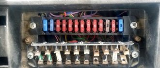
Brake system GAZ-3309
When performing various repair work, a car enthusiast can be helped by a diagram of the GAZ 3309 diesel brake system, since it has a complex device that can cause difficulties when troubleshooting problems on their own. The brakes of this vehicle allow you to stop the truck quickly and effectively, which improves driving safety.
Diagram of the brake system GAZ-3309 diesel
During the design of such a vehicle, the plant's engineers decided to develop its design almost from scratch, which made it unlike other cars of the automaker. The brake system of the GAZ 3309 deserves special mention, which is radically different from its predecessors.
When studying its structure, it is advisable to identify several categories of basic elements that ensure correct operation. These include:
- worker node;
- parking brake equipment;
- spare system.
A properly functioning braking system ensures driving safety
All of them are designed to quickly brake the truck or slow down its movement. The pneumatic-hydraulic brakes of this vehicle are reliable, which is especially important for freight vehicles, the braking distance of which is critical when dangerous situations arise on the road.
By working unit we mean the main system, which is constantly used while driving, and the spare one is a reserve in case of failure of the first one.
Brake device
Considering the design of this GAZ 3309 system, it should be noted that the standby and backup systems are combined into one set, which should be taken into account when performing repair work. In previous models, the pedal had to be pressed with considerable force to brake, but in the new design, the automaker's engineers managed to completely eliminate this drawback.
The brake design includes the following elements:
- standing brake - clamp, lever-handle, disc, handbrake cable, release element, drum, shoes, related mechanisms;
- drive part - pads, protective caps, pistons, guide brackets, shield, hydraulic cylinder reservoirs, as well as other components;
- brake cylinder - lever body, rod, guide parts, brake light switches.
Be sure to read:
Technical characteristics of GAZ-2747
An important design element is the amplifier, which is designed to increase pressure in key components. Due to this, it becomes possible to significantly increase braking efficiency without the need to exert maximum effort on the controls.
Vacuum pump features
An important design element is a vacuum amplifier, which is capable of creating the necessary pressure in the system. Due to this, it is possible to significantly increase braking efficiency, as well as reduce the required force when pressing the pedal. It should be remembered that incorrect operation of this important unit is a dangerous breakdown, leading to unstable operation of the power unit.
This is due to the entry of air into the intake pipe of the engine, which contributes to the leanness of the fuel mixture in its cylinders. As a result, the car cannot operate for a long time and periodically stalls. The design of the system involves the removal of lubricant and mechanical damage to the cylinders in the event of such a malfunction, which is why it is necessary to eliminate it as soon as possible.
Brake system GAZ 3309
Adjusting the parking brake
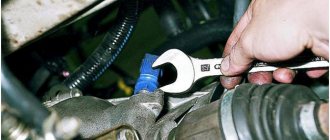
One of the most important jobs when servicing this vehicle is adjusting the parking brake. It is performed in several stages, and the car enthusiast will only need to have the necessary skills, a 24 mm wrench, and a screwdriver.
The hand brake is adjusted using the following algorithm:
- Lower the lever to the lower position and shift the gearbox to neutral;
- Raise the rear wheel on the left side using a jack, then remove the shield plug.
- Rotate it, turning out the adjusting screw with a screwdriver until it slows down, then unscrew the screw until the wheel rotates freely.
- Install the plug, lower the wheel, and then adjust the mechanism on the right side in the same way.
Doing this will help keep your parking brake system in optimal condition, ensuring it operates effectively.
Be sure to read:
BELAZ 130 tons: characteristics, cost
Brake bleeding technique
Many owners of this car are interested in how to properly bleed the brake system for more efficient operation. This is a pressing problem for many models of domestic trucks, the solution of which requires an integrated approach. You can perform such tuning by following the following instructions:
- Clean the valve mechanisms of the cylinders of each wheel.
- Unscrew the cylinder cover.
- Fill it with the fluid recommended by the manufacturer.
- Bleed the front wheels.
- Remove the brake valve cap, install the hose, and place its other end in a container with brake fluid.
- Unscrew the valve half a turn, then depress the brake pedal several times.
- Screw the valve back and bleed the remaining wheels using a similar method.
When filling brake fluid, it is advisable to remember that its optimal level is 2-3 cm below the maximum recommended level.
Device
1 – chassis; 2 – platform with extension sides; 3- over-frame device; 4 – control levers PTO and CU; 5 – oil tank; 6 – mudguards; 7 – hydraulic cylinder; 8 – PTO with control valve and oil pump; 9 – platform clamps; 10 – rear light devices, 11 – side light devices, 12 – rear underrun protection; 13 – lateral protection.
Rice. 1.1. Structure of the GAZ-3307 car: / - engine; 2 — Front wheel; 3 — air cleaner; 4 - Fuel tank; 5 - Steering wheel; 6 — car frame; 7 — rear drive axle; 8— Rear spring suspension; 9 — rear wheel; 10— Vacuum brake booster; // — cardan transmission; 12 — central transmission (parking) brake; 13 - Gearbox; 14 - Clutch; 15 - Front axle; 16 — front spring suspension
The GAZ-3307, unlike its predecessor, received a sprung driver's seat with the ability to adjust the back angle and in the horizontal plane. The instrument panel turned out to be very informative and was made of plastic. The holes for the instruments were completely molded. The front panel was made of metal.
The appearance began to differ for the better when comparing the model with its predecessor, the GAZ-53. The exterior began to have a more straightforward appearance. The same bumper protruded ahead and contained side lights. The main headlights are located on the side wings. In addition to them, on the side, there are turn signal indicators.
The mesh of the radiator grille began to be painted black, on which the inscription “GAS” was visible. Rear-view mirrors were installed on the doors, and there were two of them on each side. Overall, the appearance has become more modern and pleasant.
The body has a metal structure and can be tilted using a hydraulic method, and an electro-pneumatic device allows you to control this process. The body platform has three folding sides that need to be closed manually.
The platform can be controlled from the cabin using levers. Depending on the design used, such trucks can be unloaded using two methods. The first is tilting the platform back when it tilts 50 degrees.
There is a 2nd method, where unloading is allowed on three sides (back, left and right). It is clear that the last option is the best, most convenient and versatile. Laterally the platform tilts 45 degrees.
The truck cabin was designed in accordance with the trends of the Soviet period and had angular shapes. At the same time, compared to older versions, there is significantly more space in the cabin. The false door panels received additional side pockets, which could be used as a place to store various small items. Good thermal insulation made it comfortable to stay in the cabin while driving. The cabin of the model was borrowed from the experimental development of the GAZ-4301, presented in 1984. It was distinguished by its increased size and was designed for two people. Getting to the main controls was not difficult, since they were rationally located. Other features include seat belts, a modern dashboard, and soft upholstery on interior panels and doors.
GAZ-4301
Additionally, the car was equipped with an autonomous pre-heater, allowing you to start the engine without problems in the cold season. Another feature of the model was the air intake pipe running along the hood.
Gasoline modifications of the GAZ-3307 were equipped with a 4-speed manual transmission, and diesel versions were equipped with a 5-speed gearbox. At the same time, it was possible to distinguish a 4-speed gearbox by the characteristic howl emitted when moving.
For the first time, power steering appeared in the steering mechanism. The design itself underwent minor modifications and was a globoidal worm, complemented by a three-ridge roller. Later, a new mechanism with a screw and a ball nut appeared, which made it possible to reduce the force on the steering wheel.
The car was equipped with standard drum brakes with a hydraulic vacuum booster and a hydraulic drive. The parking brake was located on the transmission and was mechanical.
The suspension in the GAZ-3307 has not been changed. The truck had the ability to install an awning and a side. The durable and reliable chassis made it possible to carry heavy loads, therefore it was used for installing various bodies (tow trucks, dump trucks, vans, etc.). Manufactured goods, insulated, grain vans and paddy wagons were created on the basis of the GAZ-3307.
Design, maintenance and malfunctions of the GAZ-66 power steering
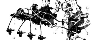
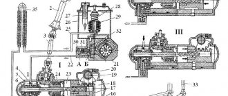
The power steering pump (Fig. 1) is of a double-acting vane type, i.e., for one revolution of the pump rotor, two complete suction and two discharge cycles are performed
The pump rotor contains vases in which the blades are placed. The blades should move freely in the vases without jamming.
In the suction cavities, oil enters the space between the blades and is then forced out into the discharge cavities. Oil is forced out by reducing the volume between the blades as the rotor rotates inside the stator, which has a special profile.
An oil reservoir is installed on the pump. There is a filler filter under the reservoir cap, and a strainer is installed on the drain hose through which the oil returns from the system to the pump.
The pump cover contains two valves. The safety valve (internal) limits the maximum pressure in the system to 65-70 kg/cm2.
The bypass valve limits the amount of oil that the pump supplies to the power steering system at increased engine speeds. The valve is designed in such a way that no more than 10 l/min of oil is sent to the hydraulic booster system.
Excess oil is bypassed inside the pump and goes back into the suction cavity.
The control valve is located at the front end of the tie rod.
Inside the valve body there is a spool, which is connected through intermediate parts to the steering arm pin.
The spool is sealed at both ends with rubber cuffs.
When the spool is in the middle position (the car is moving straight), the oil flowing through the discharge hose into the control valve is bypassed through the gaps between the ends of the spool journals and the channels in the body into the drain hose and returns to the pump reservoir.
When the steering wheel is turned, the bipod pin moves the spool, which, blocking the channels in the valve body, directs oil under pressure into one or another cavity of the power cylinder (depending on which direction the turn is made).
The power cylinder rod, connected to the tie rod, moves it, turning the front wheels.
After the end of the rotation, the spool is set to the middle position, the oil pressure in the power cylinder decreases, and the oil from the valve returns back to the pump without entering the power cylinder.
The double-acting power cylinder is mounted in a bracket on the front axle housing through a ball joint.
The rod piston is sealed with two elastic cast iron rings.
The cylinder rod is chrome plated to improve wear resistance and protect against corrosion.
The exit of the rod from the cylinder is sealed with a rubber cuff. To protect against dirt, brass washers and a felt seal are installed on the outside. The power cylinder, in addition to turning the front wheels, also absorbs impacts from the wheels when driving over various irregularities.
This significantly relieves the steering mechanism and other steering parts from shock loads.
Power steering maintenance
The power steering pump drive belts are tensioned by tilting the pump housing. The angle of inclination of the pump housing should not be too large and should ensure that oil can be filled into the pump reservoir.
If tilting the pump housing does not ensure tension of the belts, move the pump to the holes in the bracket, and if the belts are stretched too far, move the pump brackets to additional holes in them.
With normal belt tension, the deflection of each belt between the compressor and power steering pump pulleys should be 15-20 mm when the belt is pressed with a force of 4 kg.
When checking the oil level in the power steering reservoir, the front wheels of the vehicle must be installed straight.
Add oil while the engine is idling to the “oil level” mark on the wall of the pump reservoir or, if there is no mark, to the filler filter mesh.
Before removing the tank cap to check the level, top up or change the oil, it must be thoroughly cleaned of dirt and washed with gasoline.
Fill the oil through a funnel with a double mesh and a filler filter installed in the pump reservoir.
If the filters are significantly clogged with tar deposits, additionally rinse the filters with solvent No. 646, used when painting a car.
During operation, regularly monitor the tightening of the bolts securing the pump and its brackets and the bolts securing the control valve to the longitudinal link.
Regularly check the tightness of the ball pin nut securing the power cylinder to the bracket. Loosening the tightening of this nut leads to the loosening of the ball pin in the conical hole of the bracket.
Periodically check the tightness of the power cylinder rod nut and the condition of the rubber pads through which the rod is attached to the rod bracket. When the rubber cushions wear out, they must be replaced.
Oil change
To change the oil, lift the front wheels of the car and open the lid of the power steering pump reservoir.
To drain the oil you must:
— disconnect the discharge and drain hoses from the control valve body and drain the oil from the pump through them;
— disconnect the hoses from the power cylinder fittings; and drain the oil from both the control valve;
drain the oil from the power cylinder by slowly turning the steering wheel left and right until it stops.
Specifications
Specifications
| engine's type | ZMZ-511.10 |
| Travel speed (maximum) | 90 km/h |
| Load capacity | 4.5 t |
| Engine power (nominal) | 92 kW |
| Rotation frequency | 3200 rpm |
| Number of engine cylinders | 8 pcs |
| Cylinder diameter | 9.2 cm |
| Piston stroke | 8 cm |
| Working volume | 4.25 l |
| Fuel tank volume | 105 l |
| Fuel consumption per 100 km (speed 60 km/h) | 19.6 l |
| Fuel consumption per 100 km (speed 80 km/h) | 26.4 l |
| Front track size | 1.7 m |
| Rear track size | 1.56 m |
| Wheelbase | 3.77 m |
| Clearance under the rear axle | 0.265 m |
| Clearance under the front beam | 0.347 m |
| Braking distance (speed 60 km/h) | 36.7 m |
| Weight (total) | 7.85 t |
| Weight (curb) | 3.2 t |
| Width | 2.33 m |
| Cabin height | 2.35 m |
| Length | 6.33 m |
| Body type | unloadable on 3 sides |
| Body dimensions inside (length, height, width) | 3.52x0.52x2.28 m |
| Body volume (standard sides) | 5 m³ |
| Body volume (extension sides) | 10 m³ |
| Underbody area | 8 m² |
dimensions
GAZ-3307 has a rear-wheel drive, front-engine layout. Weight and dimensions of the car:
- length – 6550 mm;
- width – 2380 mm;
- height – 2350 mm;
- wheelbase – 3770 mm;
- front track – 1630 mm;
- rear track – 1690 mm;
- total weight – 7850 kg.
The truck has a ground clearance of 265 mm. Dimensions of the model platform: length – 3490 mm, width – 2170 mm, height – 510 mm. The model accelerates to 80 km/h in 64 seconds. The maximum speed for the GAZ-3307 is 90 km/h.
The car is capable of climbing hills with a slope of 25%.
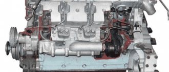
Engine
The Gorky Automobile Plant provided as many as 3 engines. Among them was the presence of an 8-cylinder V-shaped 4-stroke 4.67 liter gasoline engine ZMZ-5231.10.
It had a carburetor power system and liquid cooling and produced 124 horsepower. The compression ratio was 7.6, and it weighed about 275 kilograms. A similar power unit also received an OHV valve mechanism with an exhaust gas recirculation system, along with aluminum blocks.
Characteristics of ZMZ-5231.10.
- working volume – 4.67 l;
- rated power - 91.2 (124) kW (hp);
- rotation speed – 3200-3400 rpm;
- maximum torque – 298 Nm;
- compression ratio - 7.6 l;
- weight – 275 kg.
It can be classified as European standards Euro-3. The engine runs on AI-80 or A-76 gasoline. If you apply additional adjustment, you can use AI-92 gasoline. It was also planned to install a 4-cylinder, four-stroke, 4.75-liter, 125-horsepower diesel engine “MMZ D-245”, which had turbocharging, liquid cooling, direct fuel injection and a charge air cooler.
The GAZ-3307 was also equipped with a 125-horsepower ZMZ-511 engine, which turned out to be very gluttonous. This is what forced the Gorky Automobile Plant to begin developing modifications with a diesel engine.
Modifications of the GAZ-33078 were equipped with a Japanese 136-horsepower diesel engine Hino W04CT. However, the model, released in 1992, was not widely used.
In 1994, the Gorky Automobile Plant launched the production of diesel units on its own premises. The 5-liter 4-cylinder power plants had a rated power of 122 hp. and were equipped with turbocharging and an air cooling system.
Fuel consumption
At a speed of 60 km/h, the model’s fuel consumption is 19.6 l/100 km. When the speed increases to 80 km/h, the consumption indicator increases to 26.4 km/h. The car's fuel tank capacity is 105 liters.
Transmission
4-speed gearbox GAZ-3307
1 – input shaft; 2 – reverse light switch; 3 – clamp; 4 – gear shift lever; 5 – third gear gear; 6 – second gear gear; 7 – first gear gear; 8 – breather; 9 – secondary shaft; 10, 13 – washers; 11 – reverse gear block; 12 – bearing; 14 – bushing; 15 – crankcase; 16 – intermediate shaft; 17 – coupling
All diesel powertrains have been synchronized with a 5-speed manual gearbox. The work is carried out using an installed single-plate friction dry clutch, which has a hydraulic control drive.
But for gasoline engines, a 4-speed manual gearbox was provided, which could be easily distinguished by the characteristic howl that it emitted while driving.
Suspension
She is presented here as an addict. At the front there are semi-elliptic springs with shock absorbers. At the rear there are semi-elliptic springs with additional springs. The ends of the main sheets of all springs were installed in the rubber pads of the support brackets.
The drive goes to the rear twin wheels. The suspension was slightly redesigned, after which it was possible to better adapt it for Russian roads.
Steering
- Upper column casing assembly
- Steering wheel
- Washer 16 OST 37.001.146-75
- Nut M16x1.5-6N OST 37.001.124-93
- Overlay
- Ring A23
- Ball bearing expansion ring
- Bearing (12-3401120) GOST 520-89
- Switch for low and high beam direction indicators (66. 3709000-01) (purchased item)
- Screw M5-6gx10 OST 37.001.130-81
- Washer 5.2
- Housing seal
- Steering and ignition lock housing
- Screw M4-6gx10 OST 37.001.127-81
- Washer 4
- Ignition switch with anti-theft device assembly (export version)
- Lower column casing
- Screw M5-6gx10 OST 37.001.127-81
- Ring sealing
- Bolt M8-6gх18 OST 37.001.123-96
- Nut M8-6N OST 37.001.124-93
- Washer 8T OST 37.001.115-75
- Washer 8 OST 37.001.144-96
- Special nut
- Middle cardan shaft assembly
- Steering wedge
- Special washer
- Washer 8L OST 37.001.115-75
- Lock body clampDetails Add to bookmarks Find in price list Where else is it used
- Washer 6 OST 37.001.146-75
- Special bolt
- Steering column pipe with bracket
- Wiper/washer switch assembly (purchase item)
- Steering shaft
It has a worm mechanism, similar to a globoidal worm with a three-ridge roller.
Electrical equipment can support its own operation at 12 volts. The model did not receive a hydraulic power steering wheel.
Brake system
It is considered to be one of the most reliable. It includes brakes and hydraulic drive. In addition, the system has a pair of brake circuits, one of which is responsible for the spare brake. Each circuit has a hydraulic vacuum booster, together with a vacuum cylinder with a shut-off valve.
Thanks to vacuum cylinders, it is possible to achieve independent power supply to the circuits. The vacuum number is monitored using special vacuum measuring instruments, which are equipped with red indicators.
If the vacuum volume reaches the minimum reading, the lamp will begin to glow. There is also a parking brake, and it is represented by a mechanical method of action, and it is installed on the transmission. Drum mechanisms are used to perform braking.
______________________________________________________________________________
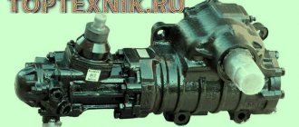
Steering GAZ-3307
The GAZ-3307 is equipped with a steering system with a globoid worm-type steering mechanism and a three-ridge roller with a three-joint steering column with a splineless connection. The engagement of the working pair of the GAZ-3307 steering mechanism (globoid worm and three-ridge roller) is designed in such a way that, with proper adjustment, the angle of free rotation of the steering wheel with the bipod disconnected in the straight-line driving position should be absent. When the steering wheel is turned in any direction by more than half a turn, the angle of free rotation appears, continuously increases and reaches 30° in extreme positions. When the car is moving, the steering must ensure the given direction and the absence of wobbling of the front wheels. The GAZ-3307 steering column is attached with four bolts to the clutch and brake pedal bracket. The steering shaft rotates on two ball bearings. The preload of the GAZ-3307 steering shaft bearings is adjusted using a special nut screwed onto the shaft. To compensate for changes in the length of the intermediate cardan shaft when the cabin oscillates, a splineless compensator has been introduced into its design.
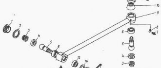
Rice. 1. Steering control of the GAZ-3307 car 1 - gasket; 2 — filler plug; 3 – shaft with worm, 4 – adjusting screw; 5 - nut; 6 - crankcase; 7 — lock washer; 8 - fork; 9 — lower cardan shaft; 10 — bearing with seal; 11 — middle cardan shaft; 12 — upper casing; 13 — overlay; 14 — steering wheel; 15 - column; 16 - lower casing; 17 — steering lock; 18 — adjusting nut; 19 — washer; 20 - wedge; 21 - self-locking nut; 22 - bipod shaft with a three-ridge roller. On the steering column of the GAZ-3307 with a two-spoke steering wheel, there is an ignition and starter switch, a switch for headlights and turn indicators, a switch for the wiper, windshield washer and sound signal, covered with decorative covers. The steering control device is shown in Fig. 1. The GAZ-3307 steering mechanism, consisting of a globoid worm with shaft 3 and bipod shaft 22 with a three-ridge roller, is mounted in a cast-iron crankcase and attached to the left frame spar with five bolts. The worm with shaft 3 is mounted on the crankcase on two tapered roller bearings. Adjusting shims 1 are installed between the bottom cover and the bearing race to adjust the preload of the worm bearings. Play in bearings is unacceptable. The bipod shaft 22 with a three-ridge roller rotates in two bearings: in a bronze bushing pressed into the steering gear housing, and in a cylindrical roller bearing installed in the side cover. The angles of rotation of the GAZ-3307 steering shaft from the average position in both directions of 45° constitute the zone of backlash-free engagement of the worm with the roller. The initial displacement of the geometric axis of the roller upward relative to the worm axis by 6 mm (for a new steering mechanism) allows the backlash-free engagement to be adjusted in operation as the worm pair wears out. The engagement of the worm with the roller is adjusted using an adjusting screw 4, which is fixed using a lock washer 7, a pin and a nut 5 screwed onto the screw. During operation, the technical condition of the GAZ-3307 steering system deteriorates due to wear of the working surfaces of parts and violation of adjustments. The technical condition of the steering is determined by the amount of total play of the steering wheel. Maintenance of the steering includes inspection, checking the condition of fasteners, checking the total play of the steering wheel, checking and adjusting the axial play in the worm bearings, checking and adjusting the gap in the engagement of the worm with the roller, and carrying out lubrication work according to the lubrication chart. It is necessary to check the oil level in the GAZ-3307 steering mechanism and, if necessary, top it up to normal. The tightness of connections is checked daily. The fastening elements of the steering wheel, steering column, steering mechanism, cardan steering gear, bipod and steering linkage arms of the GAZ-3307 must be tightened in a timely manner. The suitability of steering rod parts for further work is determined by the freedom of swing of the fingers in the assembled joint. If play is detected in the joint, it is necessary to remove the steering rod, disassemble the joint and determine the cause of the play. If parts are worn out or the finger with a cracker is buried in the liner by more than 0.5 mm, it is necessary to replace the worn parts. Before adjusting the steering rod joints of the GAZ-3307, you must make sure that there is axial play in the worm bearings. To do this, it is necessary to perform the following operations: - disconnect the hinge fork of the input shaft of the mechanism and the longitudinal steering rod from the bipod; - shake the bipod with your hand. If in this case the worm shaft has axial movement relative to the upper cover of the steering housing, the bearings require adjustment. Adjustment of the GAZ-3307 steering rod joint must be carried out in the following order: - Loosen the bolts securing the lower crankcase cover and drain the oil. — Remove the lower crankcase cover and remove the thin shim. — Reinstall the crankcase cover and check the worm bearings for longitudinal play. If the play is not eliminated, then you should remove the thick gasket and put the thin one back. — After eliminating the play, remove the bipod shaft, connect the propeller shaft fork with the worm shaft and check the force required to rotate it on the steering wheel rim. When the worm roller bearings are properly tightened, the force required to rotate the steering wheel applied to its rim should be 2.8-4.7 N (0.28-0.47 kgf). — Assemble the GAZ-3307 steering mechanism and fill in 0.6 liters of oil. The gearing adjustment should always be checked after adjusting the worm bearings in the following order: - Set the steering wheel to a straight line position. — Disconnect the longitudinal steering rod from the bipod. — While rocking the bipod in the plane of its rotation, use an indicator to determine the amount of movement of the bipod end. If the movement of the end of the GAZ-3307 steering bipod exceeds 0.3 mm, then it is necessary to adjust the gap in the engagement of the roller with the worm. To adjust, you must perform the following operations: — unscrew nut 5 and remove lock washer 7; — use a wrench to turn adjusting screw 4 clockwise until the gap is eliminated; — use a dynamometer to check the force on the steering wheel rim near the middle position; — by rotating the adjusting screw, bring the steering wheel turning force to 11.3-19.0 N (1.13-1.9 kgf); — put on the lock washer and tighten the nut. If one of the holes in the lock washer does not coincide with the pin, then the adjusting screw must be turned enough to achieve this coincidence. In this case, the steering wheel turning force should not exceed the above limits. Removing and disassembling the GAZ-3307 steering mechanism - Unscrew the steering wedge nut on the steering mechanism, knock out the wedge, remove the fork from the worm shaft. — Unscrew the nut securing the bipod. — Remove the bipod from the shaft with a puller. — Unscrew the five nuts securing the steering housing to the frame spar. — Remove the steering mechanism of the GAZ-3307. — Thoroughly clean the steering mechanism from dirt. Disassembling the steering mechanism - Drain the oil from the steering gear housing, having previously unscrewed the lower bolt securing the side cover of the crankcase. — Clamp the steering mechanism in a vice by the crankcase flange. — Unscrew the nut 5 of the adjusting screw and remove the lock washer 7 with the gasket. — Unscrew the bolts securing the side crankcase cover. — Using a light blow of a copper or aluminum drift on the end of the bipod shaft, remove the bipod shaft along with the roller and cover. — Unscrew the side cover from the GAZ-3307 steering bipod shaft and remove adjusting screw 4 from the bipod shaft. — Press the bearing out of the side cover. — Unscrew the bolts securing the upper crankcase cover and remove the upper cover along with the gaskets. — Press out the oil seal, felt ring and felt ring nut from the top cover. — Unscrew the bolts securing the bottom cover and remove it along with the gaskets. — With light blows of a bronze or copper drift, press out shaft 3 with the worm towards the bottom cover along with the outer ring of the bearing. — Press the remaining outer race of the worm shaft bearing out of the crankcase. — Press the bipod shaft oil seal out of the steering gear housing. Assembling the GAZ-3307 steering mechanism Before assembling, the parts of the GAZ-3307 steering mechanism must be lubricated with a thin layer of lubricant. Assembly is performed as follows: — Press the bipod shaft oil seal into the steering gear housing until it stops. — Install the worm shaft with bearings into the crankcase. — Install and bolt the upper and lower covers of the steering mechanism, installing as many gaskets as there were before disassembling the steering mechanism. — Adjust the tightening of the worm bearings. The tightening torque of the cover bolts is 24-36 Nm (2.4-3.6 kg/cm). — Press the oil seal, felt ring and felt ring cup into the top cover, after soaking the felt ring in heated oil. The cup of the felt ring should protrude 3.5 mm beyond the end of the lid. — Press the bearing into the side cover. — Place the adjusting screw on the shaft of the GAZ-3307 steering bipod and screw it into the cover. — Place the cover with the bipod shaft assembly into the crankcase, installing a gasket under it, and secure it with bolts, tightening torque 24-36 Nm (2.4-3.6 kg/cm). — Adjust the engagement of the roller with the worm. — Install the steering mechanism on the car. The tightening torque of the steering mechanism mounting nuts should be 44-62 Nm (4.4-6.2 kg/cm). — Install the propeller shaft fork onto the steering gear shaft of the GAZ-3307. Install the wedge into the fork and tighten it with a nut, tightening torque 18-25 Nm (1.8-2.5 kg/cm). Install a flat washer under the nut on the side of the machined surface of the fork. — Install the bipod on the bipod shaft of the steering mechanism and secure it with a nut, tightening torque 105-140 Nm (10.5-14 kg/cm). Dismantling the GAZ-3307 steering propeller shaft - Unscrew the nut securing the steering shaft wedge on the steering mechanism, knock out the wedge. — Unscrew the steering shaft wedge nut on the middle propeller shaft and remove the propeller shaft. — Unscrew the wedge nut of the GAZ-3307 middle steering shaft on the steering column, knock out the wedge and remove the middle propeller shaft with bearing and seal assembly, having first unscrewed the seal mounting bolts. — Remove the retaining rings of the crosspiece bearings. — Using a bronze mandrel, the outer diameter of which is slightly smaller than the hole in the fork, press out the crosspiece bearings on a press or in a vice. To do this, the mandrel must be installed on the bottom of the needle bearing housing and the opposite bearing must be pressed out. Turn and press out the other bearing, installing the mandrel into the end of the crosspiece tenon. — Turn the shaft 1/4 turn and press the bearings out of the ears of the second fork in the same sequence. — Take out the crosspiece. Wash all parts of the universal joint in kerosene and check their condition. — Replace worn parts. Assembling the GAZ-3307 steering cardan - Lubricate the cardan parts with a thin layer of lubricant and insert the spikes of the cross into the ears of one of the forks. — Using a mandrel, press first one bearing into the cardan fork, and then the second. — Install the retaining rings. — Turn the steering propeller shaft of the GAZ-3307 1/4 turn and, in the same sequence, press in and secure with retaining rings the other two bearings in the ears of the second fork. — Lubricate the crosspiece bearings through a grease nipple. — Install the driveshafts on the car. When installing the wedge, install the washer and nut on the side of the machined surface of the fork. — The tightening torque of the wedge nut is 18-25 Nm (1.8-2.5 kg/cm). Adjusting the GAZ-3307 steering column bearings The GAZ-3307 steering column shaft rotates on two ball bearings. If axial movement of the shaft in the column pipe is detected, it is necessary to adjust the bearings in the following order: - Remove the middle propeller shaft fork from the steering column shaft. — Bend the lock washer tab off the adjusting nut. — Rotate the nut to adjust the tightness of the bearings. With proper adjustment, the force required to rotate the steering wheel applied to its rim should be 0.22-0.75 N (0.022-0.075 kgf). Steering rods of the GAZ-3307 car The transverse and longitudinal steering rods of the GAZ-3307 have unified hinges of a non-adjustable design. The pins and joints of the steering rod fingers are most susceptible to wear. The presence of wear is determined by the appearance of a gap in the hinge. Depending on the nature of wear, it becomes necessary to replace individual parts of the hinge joint or the tip assembly. Dismantling and assembling the GAZ-3307 tie rod. Dismantling and assembling the tie rod is carried out in the following sequence: - Unscrew and unscrew the nuts securing the tie rod pins in the steering link arms. — Remove the fingers from the levers and remove the tie rod. — Clamp the tie rod in a vice, press the joint seals off the ends. — Unscrew the nuts of the tie rod ends. — Remove the ends from the tie rod rod. Disassembling the GAZ-3307 tie rod joints in the ends: - clamp the end in a vice with the cover up; - lightly press the lid inward to loosen the locking ring; - Use thin pliers to remove the locking ring; — carefully releasing the cap, remove it from the tip; - remove the cover and disassemble the hinge; — if necessary, press the liner out of the tip and replace it. Assemble the GAZ-3307 transverse steering rod in the reverse order. Before assembly, lubricate the working surfaces with a thin layer of lubricant. After installing the linkage on the car, the tip must be lubricated through a grease nipple and the wheel alignment must be adjusted. Dismantling and assembling the longitudinal steering rod of the GAZ-3307 - Unscrew the nuts securing the longitudinal steering rod fingers in the bipod and the steering knuckle lever. — Unscrew the fastening nuts, remove the pins from the holes of the bipod and the steering knuckle lever, and remove the rod. — Disassemble the steering rod joints. Assembling the longitudinal steering rod of the GAZ-3307 is carried out in the reverse order: - Before assembling the hinge, lubricate the working surfaces of the parts with a thin layer of lubricant. — After assembly, the hinge should rotate freely when the opposite end of the rod is rocked by hand. — After installing the linkage on the car, lubricate the joints with a syringe through grease fittings. When lubricating the steering rod joints, make no more than 10-15 strokes of the syringe piston so as not to damage the seals.
______________________________________________________________________________
______________________________________________________________________________
- Clutch GAZ-3308, 3309
- Dismantling the GAZ-3308, 3309 gearbox
- Drive axles GAZ-3308
- Transfer case and cardans GAZ-3308
- Cardans GAZ-3307, 3309
- Rear axle GAZ-3309, 3307
- Suspension GAZ-3309
- Steering GAZ-3309
______________________________________________________________________________
______________________________________________________________________________
- Clutch GAZ-53, 3307
- Gearbox GAZ-53, 66
- Rear axle GAZ-53
- Steering GAZ-53, 66
- Ignition installation GAZ-53
- Clutch GAZ-66
- Drive axles GAZ-66
- Brake system GAZ-66
- Winch and power take-off GAZ-66
- Operating systems of the GAZ-66, GAZ-3307 engine
- Engine ZMZ-402 Gazelle GAZ-2705
- Clutch Gazelle GAZ-2705
- Gazelle GAZ-2705 gearbox
- Front axle Gazelle GAZ-2705
- Cylinder head and camshaft Cummins ISF 2.8
- Fuel system of the Gazelle Cummins ISF 2.8 engine
- Cylinder block and piston group of the Cummins ISF 2.8 engine
- Crankshaft engine Cummins ISF 2.8 Gazelle
- Engine Cummins Valdai GAZ-33106
- Clutch and gearbox Valdai
- Bridges Valdai
- Steering Valdai
Catalogs of spare parts and assembly parts
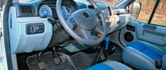
Cabin
There is more free space inside. The dashboard received an abundance of all kinds of sensors. A two-spoke steering wheel with a thin rim was installed in front of them. Among the largest sensors on the dashboard are the round powertrain speed sensor on the left and the speedometer mounted in the center.
In addition to them, there are sensors for oil, engine temperature, fuel level, battery charge and pneumatic system. More modern vehicles have fairly good seats with moderate lateral support.
To the right of the driver you can see the gearshift lever, which has a curved appearance. The entire front panel is made of plastic, and the door cards are made of pleasant fabric material.
The driver's seat itself has a sprung type, but the previous model did not have this. Moreover, the chair can be adjusted according to the angle of the backrest and in the horizontal plane.
Despite the fact that the truck cabin was developed in accordance with the standards of the Soviet era, and it had angular shapes, when compared with its predecessors, there was more free space, which, in turn, had a positive effect on comfort.
On the false panels of the doors, auxiliary side pockets appeared, which made it possible to store various small things in them. We also worked on good thermal insulation, which increased the level of comfort, and it became much more pleasant to stay inside the truck. The cabin itself was borrowed from the experimental GAZ-4301 car, which was introduced in 1984.
It had increased dimensions and was designed for a couple of people, including the driver. The main controls were fairly easy to reach. It’s very nice that they began to install seat belts, a modern instrument panel along with soft upholstery on the interior panels and doors.
Steering components of the GAZ-3307 car
______________________________________________________________________________________________________
The GAZ-3307 is equipped with a steering system with a globoid worm-type steering mechanism and a three-ridge roller with a three-joint steering column with a splineless connection. The engagement of the working pair of the steering mechanism (globoid worm and three-ridge roller) is designed in such a way that, with proper adjustment, the angle of free rotation of the steering wheel with the bipod disconnected in the straight-line driving position should be absent. When the steering wheel is turned in any direction by more than half a turn, the angle of free rotation appears, continuously increases and reaches 30° in extreme positions. When the car is moving, the steering must ensure the given direction and the absence of wobbling of the front wheels. The GAZ-3307 steering column is attached with four bolts to the clutch and brake pedal bracket. The steering shaft rotates on two ball bearings. The preload of the steering shaft bearings is adjusted using a special nut screwed onto the shaft. To compensate for changes in the length of the intermediate cardan shaft when the cabin oscillates, a splineless compensator has been introduced into its design. Rice. 1. Steering control of the GAZ-3307 car 1 - gasket; 2 — filler plug; 3 – shaft with worm, 4 – adjusting screw; 5 - nut; 6 - crankcase; 7 — lock washer; 8 - fork; 9 — lower cardan shaft; 10 — bearing with seal; 11 — middle cardan shaft; 12 — upper casing; 13 — overlay; 14 — steering wheel; 15 - column; 16 - lower casing; 17 — steering lock; 18 — adjusting nut; 19 — washer; 20 - wedge; 21 - self-locking nut; 22 - bipod shaft with a three-ridge roller. On the steering column with a two-spoke steering wheel, there is an ignition and starter switch, a switch for headlights and turn indicators, a switch for a wiper, a windshield washer and a sound signal, covered with decorative covers. The steering control device is shown in Fig. 1. The GAZ-3307 steering mechanism, consisting of a globoid worm with shaft 3 and bipod shaft 22 with a three-ridge roller, is mounted in a cast-iron crankcase and attached to the left frame spar with five bolts. The worm with shaft 3 is mounted on the crankcase on two tapered roller bearings. Adjusting shims 1 are installed between the bottom cover and the bearing race to adjust the preload of the worm bearings. Play in bearings is unacceptable. The bipod shaft 22 with a three-ridge roller rotates in two bearings: in a bronze bushing pressed into the steering gear housing, and in a cylindrical roller bearing installed in the side cover. The angles of rotation of the GAZ-3307 steering shaft from the average position in both directions of 45° constitute the zone of backlash-free engagement of the worm with the roller. The initial displacement of the geometric axis of the roller upward relative to the worm axis by 6 mm (for a new steering mechanism) allows the backlash-free engagement to be adjusted in operation as the worm pair wears out. The engagement of the worm with the roller is adjusted using an adjusting screw 4, which is fixed using a lock washer 7, a pin and a nut 5 screwed onto the screw. During operation, the technical condition of the GAZ-3307 steering system deteriorates due to wear of the working surfaces of parts and violation of adjustments. The technical condition of the steering is determined by the amount of total play of the steering wheel. Maintenance of the steering includes inspection, checking the condition of fasteners, checking the total play of the steering wheel, checking and adjusting the axial play in the worm bearings, checking and adjusting the gap in the engagement of the worm with the roller, and carrying out lubrication work according to the lubrication chart. It is necessary to check the oil level in the GAZ-3307 steering mechanism and, if necessary, top it up to normal. The tightness of connections is checked daily. The fastening elements of the steering wheel, steering column, steering mechanism, cardan steering gear, bipod and steering linkage levers must be tightened in a timely manner. The suitability of steering rod parts for further work is determined by the freedom of swing of the fingers in the assembled joint. If play is detected in the joint, it is necessary to remove the steering rod, disassemble the joint and determine the cause of the play. If parts are worn out or the finger with a cracker is buried in the liner by more than 0.5 mm, it is necessary to replace the worn parts. Before adjusting the steering rod joints of the GAZ-3307, you must make sure that there is axial play in the worm bearings. To do this, it is necessary to perform the following operations: - disconnect the hinge fork of the input shaft of the mechanism and the longitudinal steering rod from the bipod;
- shake the bipod with your hand. If in this case the worm shaft has axial movement relative to the upper cover of the steering housing, the bearings require adjustment. Adjustment of the GAZ-3307 steering rod joint must be carried out in the following order: - Loosen the bolts securing the lower crankcase cover and drain the oil.
— Remove the lower crankcase cover and remove the thin shim. — Reinstall the crankcase cover and check the worm bearings for longitudinal play. If the play is not eliminated, then you should remove the thick gasket and put the thin one back.
— After eliminating the play, remove the bipod shaft, connect the propeller shaft fork with the worm shaft and check the force required to rotate it on the steering wheel rim. When the worm roller bearings are properly tightened, the force required to rotate the steering wheel applied to its rim should be 2.8-4.7 N (0.28-0.47 kgf).
— Assemble the GAZ-3307 steering mechanism and fill in 0.6 liters of oil. The gearing adjustment should always be checked after adjusting the worm bearings in the following order: - Set the steering wheel to a straight line position. — Disconnect the longitudinal steering rod from the bipod. — While rocking the bipod in the plane of its rotation, use an indicator to determine the amount of movement of the bipod end. If the movement of the end of the GAZ-3307 steering bipod exceeds 0.3 mm, then it is necessary to adjust the gap in the engagement of the roller with the worm. To adjust, you must perform the following operations: — unscrew nut 5 and remove lock washer 7;
— use a wrench to turn adjusting screw 4 clockwise until the gap is eliminated; — use a dynamometer to check the force on the steering wheel rim near the middle position;
— by rotating the adjusting screw, bring the steering wheel turning force to 11.3-19.0 N (1.13-1.9 kgf); — put on the lock washer and tighten the nut. If one of the holes in the lock washer does not coincide with the pin, then the adjusting screw must be turned enough to achieve this coincidence. In this case, the steering wheel turning force should not exceed the above limits. Removing and disassembling the GAZ-3307 steering mechanism - Unscrew the steering wedge nut on the steering mechanism, knock out the wedge, remove the fork from the worm shaft.
— Unscrew the nut securing the bipod. — Remove the bipod from the shaft with a puller.
— Unscrew the five nuts securing the steering housing to the frame spar. — Remove the steering mechanism of the GAZ-3307.
— Thoroughly clean the steering mechanism from dirt. Disassembling the steering mechanism - Drain the oil from the steering gear housing, having previously unscrewed the lower bolt securing the side cover of the crankcase.
— Clamp the steering mechanism in a vice by the crankcase flange. — Unscrew the nut 5 of the adjusting screw and remove the lock washer 7 with the gasket.
— Unscrew the bolts securing the side crankcase cover. — Using a light blow of a copper or aluminum drift on the end of the bipod shaft, remove the bipod shaft along with the roller and cover.
— Unscrew the side cover from the GAZ-3307 steering bipod shaft and remove adjusting screw 4 from the bipod shaft. — Press the bearing out of the side cover.
— Unscrew the bolts securing the upper crankcase cover and remove the upper cover along with the gaskets. — Press out the oil seal, felt ring and felt ring nut from the top cover.
— Unscrew the bolts securing the bottom cover and remove it along with the gaskets. — With light blows of a bronze or copper drift, press out shaft 3 with the worm towards the bottom cover along with the outer ring of the bearing.
— Press the remaining outer race of the worm shaft bearing out of the crankcase. — Press the bipod shaft oil seal out of the steering gear housing. Assembling the GAZ-3307 steering mechanism Before assembling, the parts of the GAZ-3307 steering mechanism must be lubricated with a thin layer of lubricant. Assembly is performed as follows: — Press the bipod shaft oil seal into the steering gear housing until it stops.
— Install the worm shaft with bearings into the crankcase. — Install and bolt the upper and lower covers of the steering mechanism, installing as many gaskets as there were before disassembling the steering mechanism.
— Adjust the tightening of the worm bearings. The tightening torque of the cover bolts is 24-36 Nm (2.4-3.6 kg/cm). — Press the oil seal, felt ring and felt ring cup into the top cover, after soaking the felt ring in heated oil. The cup of the felt ring should protrude 3.5 mm beyond the end of the lid. — Press the bearing into the side cover.
— Place the adjusting screw on the shaft of the GAZ-3307 steering bipod and screw it into the cover. — Place the cover with the bipod shaft assembly into the crankcase, installing a gasket under it, and secure it with bolts, tightening torque 24-36 Nm (2.4-3.6 kg/cm).
— Adjust the engagement of the roller with the worm. — Install the steering mechanism on the car. The tightening torque of the steering mechanism mounting nuts should be 44-62 Nm (4.4-6.2 kg/cm). — Install the propeller shaft fork onto the steering gear shaft of the GAZ-3307. Install the wedge into the fork and tighten it with a nut, tightening torque 18-25 Nm (1.8-2.5 kg/cm). Install a flat washer under the nut on the side of the machined surface of the fork. — Install the bipod on the bipod shaft of the steering mechanism and secure it with a nut, tightening torque 105-140 Nm (10.5-14 kg/cm). Dismantling the GAZ-3307 steering propeller shaft - Unscrew the nut securing the steering shaft wedge on the steering mechanism, knock out the wedge.
— Unscrew the steering shaft wedge nut on the middle propeller shaft and remove the propeller shaft. — Unscrew the middle steering shaft wedge nut on the steering column, knock out the wedge and remove the middle propeller shaft with bearing and seal assembly, having first unscrewed the seal mounting bolts. — Remove the retaining rings of the crosspiece bearings. — Using a bronze mandrel, the outer diameter of which is slightly smaller than the hole in the fork, press out the crosspiece bearings on a press or in a vice. To do this, the mandrel must be installed on the bottom of the needle bearing housing and the opposite bearing must be pressed out. Turn and press out the other bearing, installing the mandrel into the end of the crosspiece tenon. — Turn the shaft 1/4 turn and press the bearings out of the ears of the second fork in the same sequence.
— Take out the crosspiece. Wash all parts of the universal joint in kerosene and check their condition. — Replace worn parts. Assembling the GAZ-3307 steering cardan - Lubricate the cardan parts with a thin layer of lubricant and insert the spikes of the cross into the ears of one of the forks.
— Using a mandrel, press first one bearing into the cardan fork, and then the second. — Install the retaining rings. — Turn the steering propeller shaft 1/4 turn and, in the same sequence, press in and secure with retaining rings the other two bearings in the ears of the second fork. — Lubricate the crosspiece bearings through a grease nipple.
— Install the driveshafts on the car. When installing the wedge, install the washer and nut on the side of the machined surface of the fork. — The tightening torque of the wedge nut is 18-25 Nm (1.8-2.5 kg/cm). Adjusting the GAZ-3307 steering column bearings The GAZ-3307 steering column shaft rotates on two ball bearings.
If axial movement of the shaft in the column pipe is detected, it is necessary to adjust the bearings in the following order: - Remove the middle propeller shaft fork from the steering column shaft.
— Bend the lock washer tab off the adjusting nut. — Rotate the nut to adjust the tightness of the bearings. With proper adjustment, the force required to rotate the steering wheel applied to its rim should be 0.22-0.75 N (0.022-0.075 kgf). Steering rods of the GAZ-3307 car. Transverse and longitudinal steering rods have unified hinges of a non-adjustable design. The pins and joints of the steering rod fingers are most susceptible to wear. The presence of wear is determined by the appearance of a gap in the hinge.
Depending on the nature of wear, it becomes necessary to replace individual parts of the hinge joint or the tip assembly. Dismantling and assembling the GAZ-3307 tie rod. Dismantling and assembling the tie rod is carried out in the following sequence: - Unscrew and unscrew the nuts securing the tie rod pins in the steering link arms.
— Remove the fingers from the levers and remove the tie rod. — Clamp the tie rod in a vice, press the joint seals off the ends.
— Unscrew the nuts of the tie rod ends. — Remove the ends from the tie rod rod. Disassembling the GAZ-3307 tie rod joints in the ends: - clamp the end in a vice with the cover up;
- lightly press the lid inward to loosen the locking ring; - Use thin pliers to remove the locking ring;
— carefully releasing the cap, remove it from the tip; - remove the cover and disassemble the hinge;
— if necessary, press the liner out of the tip and replace it. Reassemble the tie rod in the reverse order. Before assembly, lubricate the working surfaces with a thin layer of lubricant. After installing the linkage on the car, the tip must be lubricated through a grease nipple and the wheel alignment must be adjusted. Dismantling and assembling the longitudinal steering rod of the GAZ-3307 - Unscrew the nuts securing the longitudinal steering rod fingers in the bipod and the steering knuckle lever. — Unscrew the fastening nuts, remove the pins from the holes of the bipod and the steering knuckle lever, and remove the rod. — Disassemble the steering rod joints. Assembling the longitudinal steering rod of the GAZ-3307 is carried out in the reverse order: - Before assembling the hinge, lubricate the working surfaces of the parts with a thin layer of lubricant. — After assembly, the hinge should rotate freely when the opposite end of the rod is rocked by hand. — After installing the linkage on the car, lubricate the joints with a syringe through grease fittings. When lubricating the steering rod joints, make no more than 10-15 strokes of the syringe piston so as not to damage the seals.
______________________________________________________________________________________________________
______________________________________________________________________________________________________
- Engine parts ZMZ-511
- Clutch parts GAZ-66
- GAZ-66 gearbox
- Transfer case and cardans GAZ-66
- Drive axles GAZ-66
- Steering GAZ-66
- Front axle GAZ-3307, 3309
- Rear axle GAZ-3307, 3309
- Cardans GAZ-3307, 3309
- Suspension GAZ-3307, 3308, 3309
- Steering GAZ-3307
- Brake system GAZ-3307, 66
- GAZ-3309 gearbox parts
- Steering GAZ-3309
- Power steering and traction GAZ-3309
______________________________________________________________________________________________________
______________________________________________________________________________________________________
- Details of the main gearbox of the driving axles GAZ-3308, 33081
- Transmission driveshafts GAZ-3308, GAZ-33081
- 5-speed gearbox GAZ-3308, GAZ-33081
- Elements of the transfer case GAZ-3308, GAZ-33081
- Clutch GAZ-3308, GAZ-33081 for diesel engine
- Assembly parts of the rear axle GAZ-3308, GAZ-33081
- GAZ-3309 clutch assembly parts
- Assembly parts of the GAZ-3309 clutch drive
- Spare parts for GAZ-3309 gearbox
- Assembly parts and spare parts for the GAZ-3309 gearbox
- Assembly parts of the GAZ-3309 gearbox control mechanism
- Assembly parts of the GAZ-3309 cardan transmission
- Assembly units and parts of the rear axle GAZ-3309
- Assembly parts of the gearbox and final drive of the rear axle GAZ-3309
- Assembly parts of the front axle GAZ-3309
- Assembly parts and steering components for GAZ-3309
Advantages and disadvantages
Advantages
- Good maneuverability;
- Good ground clearance;
- No problems with purchasing spare parts and machine elements;
- Good maintainability;
- Reliable braking system;
- Reasonable cost for both new and used trucks;
- Small dimensions;
- Not afraid of the countryside;
- Various modifications;
- Various possibilities for unloading cargo;
- Unpretentious car;
- Clear and convenient controls;
- There is a seat belt;
- Decent power units;
- Good visibility;
- More free space in the cab.