Design, technical features and operation of the KAMAZ engine cooling system
All KAMAZ engines use a traditional liquid cooling system with forced circulation of coolant (using a centrifugal pump) and removal of excess heat through a heat exchanger (radiator). Structurally, this system is built in such a way that it ensures optimal operating modes of the power unit when it warms up, in warm and cold seasons, and under different loads.
The cooling system contains the following components:
- Cooling jacket for the cylinder block and cylinder head. KAMAZ vehicles use V-shaped engines with individual heads, all of which are penetrated with channels and cavities for the passage of antifreeze. During operation of the power unit, liquid from the pump is supplied to the left half of the block, from where it flows through a pipe to the right half. From each row of cylinders, fluid is supplied to the heads;
- Water pump (pump). A centrifugal type pump is used here, mounted on the left half of the cylinder block, connected to all parts of the cooling system by pipelines;
- Thermostat box. The block contains two solid-state thermostats (based on ceresin) that control antifreeze flows when the temperature of the power unit changes. The box is located on the right half of the cylinder block, it is included in the system between the pump, cylinder heads and radiator, all connections are made by pipelines;
- Radiator. The traditional design, tubular-plate, mainly uses radiators with vertical tubes. There is a “curtain” (blinds) in front of the radiator, with which you can regulate the air flow. The radiator is installed in the front of the car;
- Fan. A conventional axial one, its impeller can be made of plastic or metal. Early engines used predominantly a five-blade fan; today, fans with an increased number of blades of a special profile are often used. The fan is driven by the engine crankshaft, so it is installed in a special casing behind the radiator;
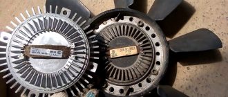
- Fan drive. Today, two types of fan drive are used - the traditional hydraulic coupling and the more modern viscous coupling. The drive not only connects the impeller to the crankshaft, but also starts and stops the impeller when the engine temperature changes.
The system operates as follows. During a cold start of the power unit, coolant from the pump is supplied to the cooling jacket, from where it is supplied to the thermostat box and, bypassing the radiator, is again supplied to the pump inlet. When the engine warms up, the thermostats open the valves and hot liquid flows to the radiator, where it releases excess heat. With even greater heating, the radiator is no longer able to cope with heat removal, so the fan turns on and provides forced airflow to the radiator. As the engine operates, its temperature constantly changes, so the fan speed constantly changes. The operation of the system is also controlled by the position of the blinds in front of the radiator.
One of the key roles in the system is played by the hydraulic coupling, which needs to be discussed separately.
How does a viscous cooling fan coupling work?
In addition to all-wheel drive, other options for using viscous couplings are known - a cooling radiator fan can serve as one such example. The operation of such a device probably does not require much explanation. In cases where the thermostat circulates coolant in a large circle, it enters the radiator, and then the cooling fan must be turned on. At other times it should be turned off.
A viscous fan coupling helps achieve this operating mode. Its device is similar to the one above, only the body has additional containers for liquid and is equipped with a valve that ensures the flow of liquid. All this is shown in the figure.
When the engine is cold, the rotating discs force fluid through the open valve into a reserve reservoir. The clutch between the discs is poor, and the viscous coupling operates with strong slippage, there is no airflow to the radiator, and the engine warms up. When the thermostat directs coolant into the radiator for cooling, it heats up, warm air from it hits the bimetallic plate located in front of the viscous coupling body, it bends, and as a result, the valve hole is blocked.
The fluid has nowhere else to go, and it remains between the disks, its viscosity increases, slippage decreases, the fan impeller is blocked on the shaft, and air flows to the radiator to cool it. This leads to a decrease in the coolant temperature; accordingly, the temperature of the air entering the bimetallic plate decreases, it returns to its original position, the valve opens, and the liquid is squeezed out into the reserve chamber.
As a result of this, the viscous fan coupling stops blocking the impeller, it begins to slip, and the cooling process of the radiator stops. Thus, it turns out that the operating mode of the cooling fan depends on the coolant temperature.
you will receive additional information about the operation of such a system. As for the ability to check the operation of the viscous fan coupling, the following video will help here
This procedure is quite simple and straightforward. It should only be noted that the viscous coupling is not disassembled; if it is faulty, it must only be replaced.
In the operation of a viscous coupling, such a characteristic of the liquid as viscosity is used. Thanks to its change, it becomes possible to implement different operating modes of devices, depending on external characteristics. We can talk about both creating all-wheel drive and cooling the radiator.
It is worth noting that if the vehicle is idle for a long time, it is necessary to inspect the viscous coupling - with a high degree of probability, its performance will significantly decrease. For preventive purposes, it is also recommended to change the oil.
Purpose of the fluid coupling, its role and place in the system
The hydraulic coupling is a key element of the fan drive; it has several main functions:
- Transfers torque from the engine crankshaft to the fan;
- Prevents a sharp change in the angular speed of the fan in the event of a sharp change in engine speed;
- Prevents shocks and all associated negative consequences when turning the fan on and off (that is, it plays the role of a damper);
- Included in the fan control system.
In this case, the fluid coupling is not an independent unit - it is included in the drive unit of engine attachments (generator, water pump), which is directly connected to the crankshaft (via the intermediate shaft). This unit is installed in the front engine cover, and most often the cover is supplied with the coupling already mounted.
The clutch functions only in conjunction with a fan regulator-switch, thanks to which the oil flow is redistributed and the fan operating mode is controlled. This unit and its operation are described below.
Design and principle of operation of a fluid coupling
The coupling consists of several main parts: a drive wheel, which has a rigid (bolted) connection with the casing, and a driven wheel, installed in the cavity of the casing next to the drive wheel, and rigidly connected to the shaft, which is installed through bearings in the casing and inside the hollow pulley shaft ( it in turn is a continuation of the drive wheel). The driving and driven wheels are two halves of a torus (“donut”) cut lengthwise; their cavities facing each other have blades. Thanks to these blades, the torque from the rotating drive wheel, due to the viscosity of the oil, is transmitted to the driven wheel, as a result of which the impeller is driven.
The casing, drive wheel and pulley shaft are rigidly connected to each other, with the casing having a spline connection to the drive shaft, which transmits torque from the crankshaft. This entire bearing structure is installed in the front cover of the engine and is closed at the back by a cover (which is called the bearing housing), and a pulley is screwed to the pulley shaft from the outside. Thus, during engine operation, this unit rotates, due to which a number of units are driven from the pulley.
There are channels in the driven wheel housing, in the casing hub and in the bearing cover that provide oil supply from the central oil line of the power unit and return to the sump. All channels converge at one point on the right row of the engine cylinder block, next to the inlet pipe of the cooling system - the fluid coupling regulator-switch is installed here.
The regulator consists of a housing in which a system of channels is made, a spool, a thermal power sensor and a handle for controlling the position of the spool are installed. When the regulator is installed on the engine, the sensor is immersed in the antifreeze flow, due to which the engine temperature is monitored and the fan is controlled.
The clutch functions quite simply. When the engine is cold, the thermal power sensor has a minimum length and the spool is closed, so oil is not supplied to the coupling cavity and it does not rotate - as a result, the fan either rests or rotates weakly under the influence of friction forces in the bearings. When the engine warms up, the sensor also warms up and lengthens, the spool opens the channels and oil enters the coupling cavity - the fan gradually begins to rotate, and as the temperature of the power unit increases, the angular speed of the impeller also increases. When the engine cools, all processes occur in reverse order.
Removing and replacing the hydraulic coupling
- Tilt the driver's cab to the second fixed position.
- Loosen the generator mounting nut.
- Remove the fluid pump drive belt.
- Remove the engine oil sump and oil cooler.
- Unscrew the mounting bolts and remove the filter responsible for centrifugal oil purification.
- Unscrew the front bracket screws and loosen the shoe nuts.
- Raise the front of the engine and place blocks of wood under the engine.
- Unscrew the bolts and washers where the front cover is attached to the cylinder block.
- Remove the fluid coupling along with the cover and casing.
- Install the new mechanism and reassemble, performing all steps in reverse order.
Issues regarding the operation of the KAMAZ hydraulic coupling
The regulator-switch can be moved to one of three positions, each of which sets its own fan operating mode:
- Automatic mode, handle in position “A”. In this case, all processes occur as described above. The limit temperature for turning on and off the impeller is in the region of 85-90°C (can be adjusted within certain limits);
- Constantly on, position “P”. In this case, the impeller always rotates and does not turn off when the motor temperature changes;
- Permanent shutdown, "O" position. In this case, the impeller is always at rest and there is no cooling of the radiator.
The driver himself selects the required fan operating mode, but in most cases the regulator is set to position “A”. It is recommended to switch to the “O” mode in the cold season and when operating the vehicle in regions with a cold climate. And the “P” mode is most often used in case of various breakdowns of the regulator or in the case of constantly high engine loads and when operating the car in hot climates.
Maintenance and features of hydraulic coupling repair
The fan fluid coupling does not require special maintenance during operation; it can operate uninterruptedly throughout the entire service life of the engine. Only sometimes it may be necessary to adjust the response temperature of the switch-regulator; this is usually done by changing the thickness of the pack of washers under the thermal power sensor. And if the clutch breaks down, it is usually replaced together with the front motor cover.
Otherwise, the fluid coupling does not remind of itself and can serve for a long time, ensuring efficient operation of the cooling system.
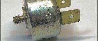
Fluid coupling switch
- switch housing cover
- switch housing
- return spring washer
- return spring
- fluid coupling switch spool
- O-ring of the switch housing cover
- faucet plug o-ring
- switch tap plug
- pin
- valve plug lever
- retainer spring
- faucet plug lever retainer
- faucet plug cover
- shims
- thermal power sensor mounting nut
- thermal power sensor
- thermosil seal ring
What is a fluid coupling and why is it needed?
An article about a fluid coupling: what it is needed for, components, operating features, possible malfunctions. At the end of the article there is a video animation of the KamAZ fluid coupling.
The fluid clutch is part of a closed system in automatic and semi-automatic transmissions. A separate fluid coupling unit (in modern car models, a torque converter) is designed for smooth transmission of torque from the crankshaft to the automatic transmission.
Principle of operation
The fluid coupling ensures smooth transitions from one gear to another, restraining rotational vibration, allowing for a smooth start of the car and fast, smooth acceleration.
The main components of a fluid coupling are two bladed wheels, which are located on the same axis.
The first blade is connected by a flexible link to the drive shaft of the car. The second blade has a clutch with the driven shaft. The inside of the fluid coupling is filled with oil.
The clutch drive shaft receives rotation from the machine engine. Under the influence of rotational movements of the working fluid, forces are transferred to the blades of the driven shaft, which begins to rotate smoothly, taking over the acceleration from the drive shaft. The connecting link between the shafts is the working fluid.
The torque converter, as a more modernized system, has an additional power part - a stator, a third wheel with blades of a certain shape. It is installed on the drive (pump) shaft, forming a single unit with the wheel.
The torque converter increases the transmission torque from the engine to the automatic transmission several times, while the clutch transmits the amount of vibration from the drive shaft with losses of 2-5%.
Main components of the hydraulic coupling:
- the wheel (pump blade) is attached to the crankshaft;
- turbine wheel, attached to the transmission shaft;
- filler plug;
- mechanical seal;
- air cooling fins;
- engine crankshaft;
- driven shaft.
Signs of wear and tear on the fluid coupling and torque converter
The hydraulic coupling is designed for the entire life of the automatic transmission, but, like any other part, it can fail much earlier.
Signs of a fluid coupling malfunction that will require contacting a car service:
- An uncharacteristic crackling sound is clearly heard in the automatic transmission when changing gears. After gaining speed, the crackling disappears. The reason may be abrasion of the support bearings.
Body vibration at speeds over 60 km per hour. The clutch working fluid has reached the end of its service life and the oil filter becomes clogged with karst oil particles. In this case, after diagnostics, all working fluids of the transmission and engine are replaced.
The car loses its acceleration torque and shows poor acceleration dynamics. The reason is the failure of the turbine clutch wheel.
A clear sign of wear or damage to the turbine wheel can be a sudden stop of the car without the ability to continue driving.
Wear or breakage of turbine wheel blades, as well as their deformation, lead to a metallic knock in the gearbox when changing gears.
- The end washer of the fluid coupling is made of aluminum. If, when checking the oil, traces of metal deposits are noticeable on the dipstick, you should check the clutch wheels and end washer.
The main feature and advantage of a fluid coupling is the protection of the automatic transmission from high torque when transmitting power from the engine. The clutch and torque converter make it possible to smooth out feed jerks and transmit torque smoothly, with a gradual increase and decrease in speed.
Video animation of KamAZ fluid coupling:
How repairs are made
So, to repair a broken part, you should start by checking the silicone fluid level . It leaks very often. It is necessary to fill in new fluid, for which the following is done:
Noise during operation of the viscous coupling indicates failure of the bearing with which it is equipped. To replace the bearing, you need to actually do the same as described above, and also perform a few more operations. For this reason, we immediately note that when replacing a viscous coupling bearing, the old silicone fluid must be drained, and immediately after replacing the part, a new portion of silicone must be poured. And here's what to do with a broken bearing:
- Remove the viscous coupling;
- After draining the liquid, remove the upper disk and dismantle the bearing using a specialized tool (puller). You will also need to grind down the flare. We strongly do not recommend removing it with improvised means. Afterwards, install a new bearing. A sealed bearing with no visible balls will do. As described above, fresh liquid is poured in;
- The device is returned to its place.
- Bimetallic strip in a “cold” state.
- The plate is heated with warm air, the inlet valve of the front chamber is open.
- The coefficient of thermal expansion corresponds to the maximum cooling mode. The rear chamber valve is open.
Fan and fluid coupling of a Kamaz vehicle
The axial-type fan, five-bladed, creates additional air flow through the core of the radiator of the cooling system.
It is mounted on the hub 15 of the driven shaft of the fluid coupling and placed in a casing
When the fan rotates, the shroud creates an air flow directed through the radiator core, thereby increasing cooling efficiency.
The fan drive is hydraulic; it consists of a fluid coupling and a switch for its operation mode.
The fan drive fluid coupling ensures transmission of torque from the engine crankshaft to the fan and reduces dynamic loads that occur when the crankshaft rotation speed changes sharply.
The switch provides automatic switching on or off of the fan.
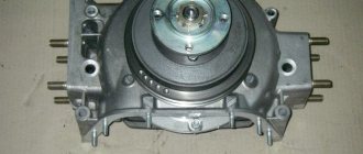
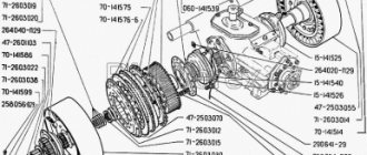
The fluid coupling is installed in the front part of the engine coaxially with the crankshaft in the cavity formed by the front cover 1 of the block and the bearing housing 2.
The drive shaft assembly with casing 3, drive wheel 10, pulley shaft 12 and generator pulley 11, connected by bolts and rotating in ball bearings 8, 19, make up the driving part of the fluid coupling. It is driven into rotation from the engine crankshaft through a splined shaft 6.
The driven wheel 9, assembled with the shaft 16 and the fan hub 15 attached to it, rotating in ball bearings 4, 13, constitutes the driven part of the fluid coupling.
The fluid coupling is sealed with rubber cuffs 17, 20. On the inner toroidal surfaces of the drive and driven wheels there are radial blades cast together with the wheels. There are 33 of them on the drive wheel, 32 on the driven wheel.
The interblade space of the wheels forms the working cavity of the fluid coupling.
The transmission of torque from the drive wheel 10 of the fluid coupling to the driven wheel 9 occurs when the working cavity is filled with oil.
When the engine is running, the oil coming from the pressure section of the oil pump through the switch channel enters the blades of the rotating drive wheel and is carried away by it, acquiring kinetic energy.
Internal oil circulation is established in the wheel cavity (shown by arrows).
Oil particles hitting the blades of the driven wheel give off energy to it, ensuring rotation of the driven parts and the fan.
The rotation speed of the driven wheel depends on the amount of oil entering the fluid coupling cavity.
KamAZ fluid coupling: how to ensure uninterrupted operation of the cooling fan?
Cars January 2, 2017
The cooling system of KamAZ vehicles is designed according to the classical principle. But there are also peculiarities.
One of them is the presence of a fan fluid coupling.
Thanks to the proper operation of this unit, the truck's cooling system operates as efficiently as possible under load.
Purpose of the fluid coupling
The most important component for ensuring effective engine cooling is the fluid coupling. Without it, KamAZ would have a continuously running cooling fan.
Its meaning is to turn on the fan at the right time and then turn it off.
After all, when the engine warms up, as well as during cold operation of the car, airflow is not needed at all.
The direct purpose of the fluid coupling is to transmit the torque of the engine crankshaft to the cooling fan at the right time. It also significantly dampens sudden changes in the operation of the crankshaft and serves as a good damper for fan drive.
How this unique cooling system unit works will be clear from its structure.
KamAZ hydraulic coupling device
Only if there is oil inside the working space will the hydraulic coupling work. KamAZ has the best designs for this.
The operation of the clutch is based on two wheels: driving (9) and driven (10). The drive wheel has 33 blades and is connected to the engine crankshaft through the splined part of the shaft (7).
The driven wheel has 32 blades and is inextricably linked to the driven shaft (16), which in turn drives the cooling fan.
The drive shaft (7) rotates in bearings 8 and 19, and the driven shaft, in turn, in bearings 4 and 13.
The clutch impellers do not contact each other without oil. That is, when turned off, only the drive wheel rotates. The slave can spin passively, thanks to the rotation of the fan when the cooling radiator shutters are open.
The fan fluid coupling has a reliable collapsible housing, consisting of a cover (1) and a casing (2). KamAZ has a well-thought-out leakage protection system. To prevent oil leakage, the fluid coupling has two oil seals (17, 20) and a gasket (18).
To ensure that oil enters the fluid coupling at the right time, there is a fluid coupling switch with a “flag” in three positions. Let's look at this simple, but at the same time integral component in more detail.
Fluid coupling switch
A metal case with a temperature sensor directly connected to the coolant is the fluid coupling switch.
KamAZ has the following temperature regime: when the temperature of antifreeze or antifreeze rises to 83-86 ° C (hot or cold switch), the working mass in the sensor begins to melt and expand, pushing the rod. The channel for oil to enter the fluid coupling opens. When the coolant temperature drops back, the spring returns the switch opening rod to its place.
What do the three positions of the fluid coupling switch do? The “flag” of the switch allows you to select three main operating modes:
- auto;
- permanently open option;
- permanently closed.
It is clear that the automatic mode is the main operating mode and, if the fan fluid coupling is working properly, it does not switch to other positions.
If a malfunction occurs in the switch (which is quite possible), it is set to the “permanently open” mode.
And at the first opportunity the switch is replaced.
The third mode of the fluid coupling switch is “permanently closed”, used when the vehicle overcomes deep fords. In these cases, fan operation is not only unnecessary, but will only cause harm.
Operating principle of the fan fluid coupling
Now, after the internal structure of the fluid coupling has become clear, it is quite simple to understand how it all works.
In automatic mode, the fluid coupling starts to move, and specifically, turns on the fan, when the coolant temperature rises to 83 oC or 86 oC.
The fan, when turned on, blows on the radiator, thereby cooling the antifreeze and maintaining the optimal engine temperature.
When the antifreeze temperature drops, the fluid coupling switch is activated and it turns off the fan rotation. After this, it can only rotate passively, from the flow of incoming air due to the movement of the car (with the radiator shutters open).
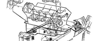
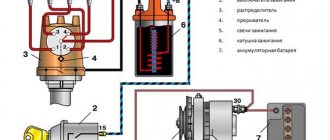
A general view of the cooling system of KAMAZ power units
Diesel engines of Kama trucks are equipped with a dual-circuit liquid cooling system built according to a traditional design. It consists of a water jacket (a system of cavities and channels) in the cylinder block and in the cylinder head, a liquid pump (pump), several thermostats, a radiator, a piping system and various sensors. This system also includes a fan that removes excess heat from the radiator at certain engine operating modes.
The functioning of the system is as follows. When you start the engine, the pump immediately starts working, which circulates antifreeze in the first (small) circuit, bypassing the radiator. When the power plant warms up, the thermostat is activated, which opens the path of coolant to the radiator, which ensures cooling and maintains a certain temperature of the engine.
However, the radiator does not always work efficiently - at high speeds, as well as in hot weather, the removal of excess heat into the atmosphere is significantly worse, which can lead to overheating and engine failure. The fan included in the cooling system solves the problem - it creates an air flow that blows over the radiator, removing excess heat. Without a fan, normal operation of the car, especially in the warm season, would be impossible.
The operation of the fan is ensured by a special unit - the fan drive clutch. Until recently, KAMAZ vehicles used exclusively a hydraulic coupling (fluid coupling) paired with a regulator-switch. Today, Kama trucks are increasingly equipped with simpler viscous couplings (viscous couplings). Here we will pay attention only to the fluid coupling - a solution that is still popular and has a number of advantages over the viscous coupling.
Procedure for replacing fluid in a viscous coupling
If diagnostics of the unit showed a low level of silicone grease in the main unit, it is quite possible to fix this malfunction yourself. You just need to follow a certain sequence of actions:
Recommendation: immediately after installation, check the functionality of the repaired unit, especially before traveling long distances. Otherwise, there is a high risk of engine overheating.
Sources
https://www.autoars.ru/articles/?name=Gidromufta_KAMAZ_rabota_ventilyatora_ohlazhdeniya https://b2b.rumotors.com/review/mufty-ventilyatora-na-gruzovyh-avto-konstruktivnye-razlichiya-i-naznachenie https:// hottecke.ru/products/muftyi-vyazkostnyie/ https://www.autoopt.ru/articles/products/1388292/ https://auto.today/bok/3517-mufta-ventilyatora.html https://avto.pro /autonews/viskomufta_ventilyatora_ustroystvo_neispravnosti_i_remont-20181211/ https://autolirika.ru/teoriya/viskomufta-ventilyatora.html https://atkomplekt.ru/borgwarner_electronic_fan_drives https://7gear.ru/remont/mufta-kamaz.html https:// uremont.com/publications/articles/remont-viskomufty
Purpose of the fluid coupling and its role in the cooling system
The fluid coupling has several undoubted advantages and disadvantages over the viscous coupling and electric fan drive, which determines its wide distribution. Compared to a viscous coupling, a fluid coupling works more reliably and efficiently; it switches on and off more clearly, ensuring reliable cooling of the radiator. And compared to an electric drive, a hydraulic clutch makes an entire electrical circuit with its fuses, relays, sensors and wiring unnecessary. At the same time, the more complex design of the fluid coupling is fully compensated by its reliability and efficiency, which are not available to the viscous coupling and electric motor.
The hydraulic coupling performs several functions:
• Power take-off from the crankshaft to the fan; • Smooth connection and disconnection of the cooling fan from the crankshaft; • Damping of loads and reactive moments that arise when the fan is connected and disconnected, as well as when the operating mode of the power plant changes.
However, it should immediately be noted that the fluid coupling itself is an ineffective unit; it can normally perform its functions only in conjunction with a regulator-switch. This unit controls the operation of the hydraulic coupling and solves several problems:
• Turning the fan on and off automatically when the threshold temperature is reached; • Constant turning on or off of the fan, regardless of the degree of heating of the motor; • Ensuring optimal impeller rotation speed depending on the current temperature of the power plant.
Working in pairs, the clutch and regulator control the operation of the fan and the entire diesel cooling system as a whole. So these nodes play an important role, but at the same time they are not complicated or expensive.
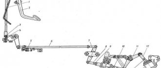
Fan drive operating modes
There are three operating modes of the fluid coupling. Changing the mode is achieved by changing the position of the switch flag. The positions are indicated in the image below, and the operating modes are also described.
- Auto mode. The coolant temperature in the engine is maintained at 80-95 degrees. The hydraulic coupling switch valve is set to position B (mark on the switch body)
- The fan is turned off. The hydraulic coupling switch valve is set to position O. In this case, the fan can rotate at a low speed.
- The fan is constantly on. (locked) Operation in this mode is allowed only in emergency cases in case of malfunctions for operation in automatic mode. Operating the fan for a long time without turning it off can lead to wear and tear of the impeller. To enable this mode (if necessary), you will need to loosen the locknuts of two special bolts securing the impeller to the hub and screw the bolts so that they fit into the hole on the fan drive pulley. Retighten the nuts. When returning to automatic mode, unscrew the bolts and lock them in such a position to ensure free rotation of the fan relative to the pulley and reliable fastening of the impeller to the hub.
KAMAZ hydraulic coupling design
The hydraulic coupling has a simple design. Its basis is a drive wheel, made in the form of a torus (“donut”) cut along the torus, and connected to the casing by means of several bolts. The casing itself is rigidly mounted on the drive shaft, which, in turn, is mounted on the rear wall of the coupling using a bearing. The drive shaft has a splined connection with the clutch drive shaft, which plays the role of an intermediary between the clutch and the crankshaft. From the outside, the annular pulley hub and the generator drive pulley itself are attached to the drive wheel.
Inside the casing there is a driven wheel, which is also a cut torus, with its flat side turned towards the drive wheel. The inner surfaces of both wheels, which have a toroidal shape, have blades located along the radius. The wheels are solid cast (with blades), which significantly increases their reliability and strength. There are 33 blades in the drive wheel of the clutch, and one less in the driven wheel. There is a small gap between the wheels, which is necessary for the supply and removal of oil. The space between the wheels and their internal surfaces turned towards each other form the working cavity of the hydraulic coupling.
A driven shaft is rigidly connected to the driven wheel, which is passed through a hole in the center of the drive wheel and through the pulley hub, and ends at the fan hub. The fan impeller is mounted on the hub using bolts and can be removed if necessary. The driven shaft rests on one bearing located inside the pulley hub, the second support is a bearing in the casing.
Operating principles of a hydraulic coupling
The hydraulic cooling fan drive can operate in three different modes:
• Automatic mode - the cooling fan is connected and turned off automatically when the threshold motor temperature is reached; • Forced permanent shutdown - the fan is always turned off (however, in this mode, the impeller can rotate slowly, as it is affected by the incoming air flow, and rotation can also occur due to friction inside the clutch bearings); • Forced constant fan activation - the impeller always rotates.
Switching between modes is carried out using a lever on the control switch. The automatic mode is indicated by the letter “A” or “B” (depending on the specific type of regulator), permanent shutdown by the letter “O” (“disconnected”), permanent on by the letter “P” (“connected”). We are most interested in the first mode.
In automatic operating mode, the coolant temperature is monitored using a thermal power sensor, which is a sealed, sealed, small-volume cylinder filled with an active mass that changes its volume when melted. The active mass is usually granulated wax mixed with granules of metals, graphite and other materials. That is, the same technical solution is used here as in the thermostat.
When the engine heats up slightly (less than 85°C), the sensor has a small volume, so the valve is closed and blocks the access of oil to the fluid coupling. When the engine heats up to 85°C or higher (depending on the adjustment), the mixture filling the sensor melts, the length of the sensor increases, and it acts on the valve, as a result of which the oil channels open in the regulator - in this case, oil from the main line under pressure enters the front the cover of the cylinder block, where it is fed through a channel and a special tube in the bearing housing to the drive shaft of the fluid coupling, and through the channels in it into the working cavity of the fluid coupling.
Oil under pressure completely fills the working cavity of the coupling, where it begins to rotate under the action of the moving blades of the drive wheel - this flow interacts with the blades located on the driven wheel, transfers part of its kinetic energy to them, and also causes them to rotate. As a result, both wheels begin to rotate almost as a single whole, and together with them the fan impeller is also driven into rotation. However, oil does not provide a rigid connection between the wheels, therefore, when the crankshaft rotation speed changes, the driven wheel, due to the viscosity of the oil, changes its angular velocity gradually, preventing impacts and uneven operation of the fan.
The switch-regulator works in such a way that the amount of oil supplied to the fluid coupling at any given time depends on the engine temperature - the higher it is, the more oil. Therefore, the hotter the motor, the faster the fan rotates. The regulator also provides the ability to adjust the threshold temperature for turning on and off the fluid coupling in the range from 85 to 90°C.
When the temperature of the power unit drops below 85°C, the mixture in the sensor solidifies again, its volume decreases, which leads to the closure of the valve. The oil stops flowing into the clutch, and the oil that remains between the wheels, under the influence of centrifugal forces, gradually drains into the oil pan through a hole specially provided in the casing. When the amount of oil is reduced, the drive wheel stops influencing the driven wheel, and the impeller stops rotating.
It is important to note that the driving part of the fluid coupling (it includes the fluid coupling drive shaft and the drive shaft, the drive wheel with the casing, as well as the pulley hub and the generator pulley itself) always rotates regardless of the engine temperature. This ensures constant generator drive, even if the fluid coupling is disconnected or damaged.
As is easy to understand, forced activation and disengagement of the fluid coupling is ensured by the opening or closing of the oil channels in the regulator-switch. Forced opening and closing of the channels is done by turning the plug with holes located in the upper part of the regulator. When the lever (and plug) is in the “O” and “P” modes, the valve continues to operate, but does not affect the operation of the regulator.
Check the serviceability of the fluid coupling of the KAMAZ 740 engine fan drive
Tools and accessories: wrenches 14, 17, 19, 22 and 32 mm, socket wrench 13 mm, crowbar for turning the crankshaft, container for draining the coolant.
Duration of work: 45 min.
Promotional offers based on your interests:
Contents of work and technical conditions Checking the fluid coupling switch
The fluid coupling switch is checked by turning on the fan in each of its three modes.
Automatic mode 1. Set the switch tap to position “B”, for which place the switch rod in the uppermost position. 2. Start the engine. The fan should automatically turn on at a temperature of 90 °C and turn off at a temperature of 85 °C, thereby maintaining the coolant temperature within the required limits. 3. Adjust the stroke of the thermal power sensor of the fluid coupling switch if the coolant temperature increases (when the fan is operating in automatic mode) more than 105° C.
The fan is turned off 1. Set the switch tap to position “0”, for which the switch rod 2 is set to the middle position. 2. Start the engine. The fan should not turn on. Its rotation is allowed at a low frequency.
The fan is constantly on 1. Set the switch tap to the “P” position, for which the switch rod 2 is placed in the lowest position. 2. Start the engine. Regardless of the coolant temperature, the fan is constantly on.
Adjusting the fluid coupling switch 1. Drain the coolant from the cooling system. 2. Unscrew the nuts and remove the centrifugal oil filter cap and the poTopat cap. 3. Loosen the locknut and the nut of the lever securing the hydraulic coupling drive belt tensioner. 4. Unscrew the bolts of the hydraulic coupling switch rod guide bar, remove the bar and rod. 5. Unscrew the switch housing bolts and remove the fluid coupling switch from the engine. 6. Secure the fluid coupling switch in a vice, unscrew the nut 15 securing the thermal power sensor and remove sensor 16 from the housing 7. Adjust the stroke of the fluid coupling switch spool. If the fan is turned on late in automatic mode, it is necessary to remove one or more adjusting washers 14 located between the sensor and the switch housing. When turning on the fan early, the number of washers must be added. 8. Tighten the nut securing the thermal power sensor with a torque of 2-2.5 kgf-m. 9. Install the fluid coupling switch on the engine and secure it. 10. Install the switch rod with the guide bar and secure it with bolts. 11. Adjust the tension of the hydraulic coupling drive belts in accordance with technological map No. 21. 12. Install and tighten the nuts of the rotor caps and centrifugal oil filter. 13. Fill the system with coolant. 14. Start the engine and check the operation of the fluid coupling switch.
Rice. 1. Fluid coupling switch for the KamAZ-740 engine: 1 - switch housing cover; 2—thrust; 3 — switch housing; 4 — return spring washer; 5 — return spring; 6 — spool of the fluid coupling switch; 7 — sealing ring of the housing cover; S - sealing ring of the valve plug; 9 — switch tap plug; 10 — valve plug lever; 11 — clamp spring; 12 — faucet plug lever clamp; 13 — valve plug cover; 14 — adjusting washers; 15 — nut for fastening the thermal sensor; 16 — thermal power sensor assembly; 17 - sealing ring of thermal power sensor
Source