KAMAZ relay valve operating principle malfunction
KAMAZ accelerator valve
Accelerator valve
We install the KAMAZ accelerator on Foton 1093
Relay valve Kamaz
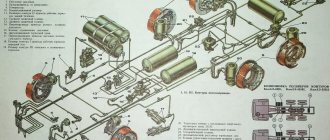
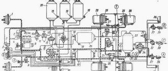
KAMAZ brake system
Operating principle of the relay valve
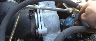
Air leak from the brake valve KAMAZ ZIL PAZ MAZ KRAZ GAZ
Air leak from the brake valve KAMAZ ZIL PAZ MAZ KRAZ GAZ
How the WABCO ABS pneumatic braking system works
Brake systems KamAZ
Also see:
- Stand for adjusting KAMAZ injectors
- Clutch for Yamz with KAMAZ gearbox
- Warm cabin KAMAZ
- Mafia KAMAZ video
- High pressure fuel pump KAMAZ 740 device video
- Brake mechanism KAMAZ 5410
- Air suspension device KAMAZ 5308
- How to check the viscous coupling of a fan on a KAMAZ
- Alexander Smirnov KAMAZ
- Muffler pipe KAMAZ Cummins
- Types of KAMAZ jet rods
- KAMAZ 5460 in mud video
- Calector for KAMAZ
- How to adjust the clutch drive on KAMAZ video
- KAMAZ 5320 speed diagram
Home » New products » KAMAZ accelerator valve operating principle malfunction
kamaz136.ru
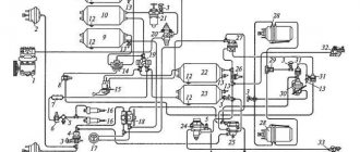
How does the energy accumulator work on KAMAZ?
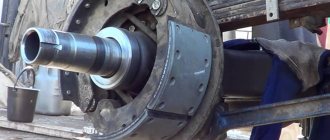
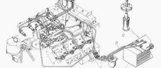
The design of the KAMAZ energy accumulator involves its attachment to the brake chamber of the rear drive axle and the middle drive axle to form a common braking device, which includes the brake chamber and the energy accumulator cylinder. The brake chamber has a body consisting of 2 halves. Between these halves there is a rubberized diaphragm. Below the diaphragm there is a metal support disk, which is connected to the rod. Under this disk there is a conical spring.
The rod is connected to a lever that enters the brake pad expansion cam, being covered with a rubber cover that prevents the penetration of dirt and dust. The energy accumulator cylinder contains a hermetically sealed steel piston with a seal. The piston experiences the influence of a powerful power spring, which tends to hold it in the lowest position, which corresponds to the braked state of the car. A support washer is installed at the bottom of the piston, and a steel pipe is also pressed into it, into which, in turn, a pusher with a seal is inserted. The top of the brake chamber pipe has an O-ring seal.
A device is installed in the pipe that mechanically releases the wheels to move the car to a safe place or tow it in the event of a brake drive malfunction. The device includes a steel screw that is screwed into a boss that is welded to the top of the cylinder, and a thrust retaining ring that locks a bearing with a rubber ring and races on the screw shank. The cavity of the cylinder located on top is connected through a pipe to the cavity of the chamber under the diaphragm, which communicates with the atmosphere.
Kamaz brake malfunctions
| Cause of malfunction | Remedy | |
| The pneumatic system receivers are not filled with compressed air or are filled slowly. Pressure regulator does not work | ||
| Damaged hoses and pipelines | Replace hoses and pipelines | |
| The tightening of the joints of pipelines, hoses, connecting and transition fittings is loose | Tighten the connections. Replace faulty connection and sealing parts | |
| The tightening of the body parts of the devices is loose | Tighten the fastening of the body parts | |
| Equipment malfunction Receiver seal is broken | Replace the faulty device Replace the receiver | |
| The pressure regulator often operates when the pneumatic system receivers are full | ||
| Leakage of compressed air in the line from the compressor to the safety valve block | Fix the leak | |
| The pneumatic system receivers are not filled with compressed air. The pressure regulator is activated | ||
| Pressure regulator incorrectly adjusted | Adjust the pressure regulator, replace if necessary | |
| The pipelines in the area from the pressure regulator to the safety valve block are clogged | Inspect the pipelines, remove and blow them if necessary, replace damaged ones | |
| Circuit III receivers are not filled | ||
| Double safety valve faulty | Replace faulty valve | |
| Supply pipes are clogged | Blow out pipelines | |
| The body of the double safety valve is deformed due to excessive tightening of the bolts securing the valve to the frame side member | Ensure that the bolts securing the double safety valve to the frame side member are evenly tightened | |
| Receivers of circuits I and II are not filled | ||
| The triple safety valve is faulty. The supply lines are clogged. | Replace the valve Blow out the pipelines | |
| Trailer (semi-trailer) receivers are not filled | ||
| The control devices for the trailer brake mechanisms located on the tractor or in the pneumatic system of the trailer (semi-trailer) are faulty. | Replace the faulty device | |
| The pressure in the receivers of circuits I and II is higher or lower when the pressure regulator is operating | ||
| The two-pointer pressure gauge is faulty. The adjustment of the pressure regulator is broken. | Replace the two-pointer pressure gauge Adjust the pressure regulator, replace if necessary | |
| Ineffective braking or failure of the vehicle to brake when the pedal is fully depressed | ||
| Brake valve faulty Leakage of compressed air in the lines of circuits I and II behind the brake valve | Replace the brake valve Fix the leak | |
| The adjustment of the brake valve drive is broken | Adjust the brake valve drive | |
| The brake force regulator drive is incorrectly adjusted | Adjust the brake force regulator or replace it | |
| Pressure relief valve faulty | Replace pressure relief valve | |
| The permissible stroke of the brake chamber rods has been exceeded | Adjust the stroke of the brake chamber rods | |
| Ineffective braking or lack of braking of the vehicle with a spare brake, insufficient effectiveness of the parking brake | ||
| Faulty accelerator valve, parking brake control valve | Replace faulty brake system | |
| Circuit III lines or hoses are clogged | Clean the pipelines and blow them out with compressed air. Replace if necessary | |
| Spring energy accumulators are faulty | Replace a faulty brake chamber with a spring energy accumulator | |
| The permissible stroke of the brake chamber rods has been exceeded | Adjust the stroke of the brake chamber rods | |
| Rear bogie brakes are faulty | Repair | |
| When installing the parking brake valve handle in a horizontal position, the car does not release the brakes | ||
| Air leakage from the circuit III pipes or the atmospheric outlet of the relay valve | Eliminate the leak using the methods specified in paragraph 1 | |
| When the vehicle is moving, the rear bogie brakes without activating the service brake and the parking brake control valve. | ||
| The two-section brake valve is faulty. The adjustment of the brake valve drive is broken | Replace the valve The brake valve drive has been adjusted | |
| The spring energy accumulator with working chamber | Replace the brake chamber with spring energy accumulator | |
autoruk.ru
How to check and repair the accelerator pump of a Solex carburetor
Preparation for testing the Solex accelerator pump is no different from preparing the accelerator pump for a DAAZ Ozone carburetor. In the same way, fuel is pumped into the carburetor and the top carburetor cover is removed.
Checking the operation of the Solex accelerator pump
Turn the throttle lever and watch how injection occurs in the carburetor. The jets from the sprayers should be smooth, strong, free of breaks, and not touch the walls and axis of the throttle valve. The injection must last for at least two seconds.
If the stream is weak and crooked, then you should clean the channels, sprayer, jets and valves. If jets of fuel hit the chamber walls, you need to adjust the position of the spray nozzles using pliers.
Solex carburetor accelerator pump repair
Repairing the Solex accelerator pump, as in the case of the DAAZ system, must begin with repairing the nozzles. The sprayer is carefully removed using a screwdriver. You need to shake it immediately to check for the presence of a discharge valve ball. In domestically produced carburetors, there are known cases where the ball was forgotten to be installed at the manufacturer's plant. Usually, if no sounds are heard, then there is significant pollution. If you cannot clean the element, it should be replaced with a new one. During the cleaning process, both spouts must be thoroughly blown out with compressed air. If this procedure does not help, the spouts are soaked in a special solution for a couple of hours and the blowing is repeated. If this does not help, then a replacement is needed.
Accelerator pump valves and channels
If there is no strong jet, you need to clean all the valves and channels of the UN carburetor. They are cleaned with wire, followed by washing and blowing.
The hole from the sprayer is filled with acetone and cleaned with a toothpick. To clean the channel hole, you need to remove the spring and diaphragm. The hole itself is cleaned with thin wire and blown through. The float chamber also has a hole, which is cleaned in the same way.
During assembly, be sure to check the condition of the diaphragm. If there are abrasions or damage, it is replaced with a new one.
When the accelerator pump cover is put back on, you need to turn the pump lever all the way so that the diaphragm stretches. Only after this are the screws tightened.
Many people are afraid of the process of repairing the carburetor accelerator pump, but if you have too much time, you can do this procedure yourself, unless, of course, you are afraid of the monotonous cleaning process.
If you have any questions, leave them in the comments below the article. We or our visitors will be happy to answer them
Accelerator valve of the KAMAZ brake system malfunction
KAMAZ accelerator valve
Why KamAZ slowly puts on the handbrake
Air leak from the brake valve KAMAZ ZIL PAZ MAZ KRAZ GAZ
We install the KAMAZ accelerator on Foton 1093
Brakes jam on KAMAZ ZIL GAZ PAZ LAZ MAZ. Brake valve repair.
KAMAZ brake system
Brake systems KamAZ
How the WABCO ABS pneumatic braking system works
Accelerator valve
Relay valve Kamaz
Also see:
- Internal dimensions of the KAMAZ 65115 body
- Air cylinder from KAMAZ
- KAMAZ 6520 beet truck
- Repair and maintenance of KAMAZ vehicles
- Replacement of KAMAZ engine liners
- Ignition installation diagram for KAMAZ Euro 3
- The device of the KAMAZ telescopic hydraulic cylinder
- Which is better KAMAZ or Tatra
- Euro KAMAZ tables
- Front hub oil seal KAMAZ 43118
- Fuel consumption of KAMAZ 5410 with trailer
- KAMAZ company resources
- Volume of a KAMAZ-based garbage truck
- Poor air pumping on KAMAZ
- Preheater for KAMAZ 65 115
Home » Clips » Accelerator valve of the KAMAZ brake system malfunctions
kamaz136.ru
Quick release valve
9.13. Quick release valve.
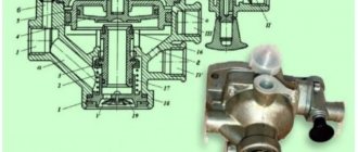
Quick release of long control lines or brake lines and brake cylinders. The appearance and structure are shown in Figures 240, 241.
In the absence of pressure, the pre-stressed diaphragm (a) lies on pressure relief channel 3 and with its outer edge blocks the passage from outlet 1 to chamber A. Compressed air coming from outlet 1 presses the edge of the diaphragm back and enters through outlet 2 to those connected further brake cylinders.
When the pressure at terminal 1 drops, under the influence of higher pressure in chamber A, the diaphragm (a) bends upward. The further connected brake chambers are fully or partially - depending on the degree of pressure drop at terminal 1 - released through pressure relief channel 3.
Installation recommendations.
The quick release valve should be installed vertically, with bleed port 3 pointing downwards. To secure it, two M8 bolts are used.
Figure 241. Overall dimensions. Terminal designations: 1 - power supply; 2 - energy extraction; 3 - pressure relief channel
Figure 240. Appearance, structure and symbol
Source
Brake system KAMAZ 6520 accelerator valve
KAMAZ accelerator valve
KAMAZ brake system
Air leak from the brake valve KAMAZ ZIL PAZ MAZ KRAZ GAZ
KamAZ. State Customs Committee for the cabin.
Operating principle of the relay valve
How the WABCO ABS pneumatic braking system works
We install the KAMAZ accelerator on Foton 1093
A small upgrade. Body lift valves, replacing old ones with euro ones
Accelerator valve
Relay valve Kamaz
Also see:
- What is the best way to refuel KAMAZ?
- How to install a turbine correctly on KAMAZ
- KAMAZ 44101 for spin tires
- Consumption KAMAZ device
- KAMAZ ko 8m3
- How to get to the KAMAZ automobile plant
- Uds 114 on KAMAZ 53228 chassis
- Dream Interpretation: dream of driving a KAMAZ
- Modernization of KAMAZ gearbox
- KAMAZ starter catalog number
- KAMAZ 65117 manipulator reviews
- KAMAZ three axis
- Battery for KAMAZ vehicle
- Instrument panel KAMAZ 65111
- KAMAZ 5410 with a manipulator
Home » Popular » Brake system KAMAZ 6520 accelerator valve
kamaz136.ru
Trailer release valve
9.17. Trailer release valve.
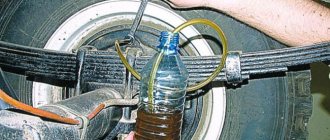
Release of the brake system for movement of the semi-trailer in the uncoupled state. In addition to the existing double release valves, new variants are available in which both the "travel" and "locked" positions can be secured with a safety pin. The appearance and structure are shown in Figures 248 and 249.
When coupling a trailer to a tractor, make sure that the piston (a) is not in the “park” position; if this is the case, the piston must be manually moved to the “drive” position. When the coupling heads are engaged, compressed air enters through port 1-1 into chamber A. If the piston (c) is still in the “disengaged” position, it is moved to the “travel” position by the supplied compressed air. Compressed air penetrates through port 21 to the trailer brake valve and then into the trailer receiver.
From the receiver, compressed air enters through port 1-2 into chamber B, opens the return valve (b) and through chamber C and port 22 penetrates the downstream connected two-line quick release valve and brakes the chambers of the spring energy accumulators of the Tristop® cylinder.
Disassembly assembly
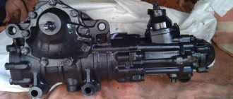
Place the valve in a vice with the atmospheric outlet facing up and clamp the body. Remove locking ring 10 with round pliers and remove guide cap 3, spring 11 and body 4 with valves 5 and 8 from body 2.
Unscrew the bolts 12 and remove the housing 2. To dismantle the piston 7, it is necessary to supply air under a pressure of 0.05 MPa at port 2, covering the piston 7 with your hand on top.
After disassembling the accelerator valve parts, they must be washed, dried and inspected. Cracks, chips and other noticeable defects are not allowed on the surface of body parts. Parts must be cleaned of rust and dirt. All rubber parts must be replaced with new ones.
Before assembling the valve, the parts must be lubricated with Ciatim -221 lubricant. The valve assembly and rubber rings must be carefully installed without damage. The valve is reassembled in the reverse order of disassembly.
Valves, rubber O-rings and other rubber parts must be assembled carefully to avoid damaging them. The presence of scratches, cuts and other defects on the surface of these parts is not allowed.