Operating principle of viscous coupling
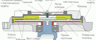
The operation of a viscous coupling is based on simple principles, one of which is contained in its name: the transmission of torque from the rotor to the housing is ensured by the viscosity of the working fluid. And the clutch control is provided by two sensitive elements - a bimetallic spiral spring and a bimetallic plate. When the temperature changes, the bimetallic spring unwinds and twists, ensuring rotation of the bimetallic plate attached to the pin. In turn, the bimetallic plate bends or straightens when the temperature changes, opening and closing the channels.
When the engine is cold (immediately after starting), the viscous coupling is at a low temperature, the spring is at its minimum length, the bimetal plate is pressed against the index plate, and the intake ports are closed. In this case, the clutch rotor rotates freely and, due to centrifugal forces and teeth at the end, holds the working fluid in the reservoir. Thus, the working chambers remain empty, and the torque from the rotor is not transmitted to the housing. Although in this case the fan rotates at a low speed, since there is some friction in the bearings.
When the engine heats up, the clutch also heats up due to the incoming air flow blown through the radiator. When heated, the bimetallic spring unwinds and rotates the bimetallic plate, which moves and opens one inlet channel - the working fluid enters the front working chamber. Due to the viscosity of the liquid, “viscous friction” occurs between the rotor and the plate, the torque is partially transmitted from the rotor to the housing, and the fan begins to rotate. The fan rotation speed depends on the heating of the engine, since the more the viscous coupling is heated, the more the inlet channel opens, and the more liquid enters the working chamber.
When the engine heats up significantly, the bimetallic plate bends, as a result of which the second inlet channel opens, through which the working fluid enters the second working chamber, the friction forces between the rotor and the dividing plates increase, and the torque is transmitted to the fan impeller with minimal losses. When the intake ducts are opened to maximum, the fan rotates at approximately the same speed as the water pump pulley.
When the engine cools, reverse processes occur: first, the bimetallic plate returns to its original position, closing one intake channel, and then the plate rotates and closes the second channel.
After the engine is completely stopped, the working fluid flows into the lower part of the tanks and working chambers, which is a certain problem: when the engine is subsequently started, the working fluid will not be able to immediately leave the working chambers, the fan will begin to rotate, which will interfere with normal warming up of the engine. This problem is solved by the presence of a large volume rear tank, which is located just below the level of the working chambers. When the engine is stopped, the working fluid flows into this reservoir and practically does not occupy the volume of the working chambers, therefore, when the engine is subsequently started, the fan will rotate at a low speed, without interfering with warming up.
Today, special silicone-based compounds are used as working fluids. Such compositions have an interesting effect (called dilatant) - their viscosity increases sharply at high shear strain rates. That is, while in the reservoir, such a liquid behaves like a regular lubricant, but as soon as it gets into the working chamber between the moving plates, its viscosity increases. It was this property of dilatant liquids that made the very existence of viscous couplings possible.
Specifically, in hydraulic couplings of domestic and most foreign cars, a special polymethylsiloxane fluid PMS-10000 (TU 6-02-737-78) is used. This liquid is sold, so it is possible to carry out independent repairs and maintenance of viscous couplings.
Thus, the viscous clutch operates automatically, providing a change in fan speed depending on changes in engine temperature, without resorting to complex sensors, without wasting electricity, and without requiring driver intervention. This is very convenient and effective, which led to the widespread use of viscous couplings on UAZ vehicles.
Purpose of viscous coupling
As the engine temperature rises, the thermostat valve opens and hot fluid begins to flow into the radiator. The latter is cooled by oncoming air when the car moves, the temperature of the antifreeze drops, and it returns in a cooled state to the head and block jackets.
When the car's speed is low or non-existent at stops with the engine running, the radiator is not ventilated and the engine begins to overheat.
It is necessary to start rotating the fan impeller, which previously rotated slowly and did not consume excess energy. This is what the viscous fan coupling is designed for.
Fan and fluid coupling of a Kamaz vehicle
The axial-type fan, five-bladed, creates additional air flow through the core of the radiator of the cooling system.
It is mounted on the hub 15 of the driven shaft of the fluid coupling and placed in a casing
When the fan rotates, the shroud creates an air flow directed through the radiator core, thereby increasing cooling efficiency.
The fan drive is hydraulic; it consists of a fluid coupling and a switch for its operation mode.
The fan drive fluid coupling ensures transmission of torque from the engine crankshaft to the fan and reduces dynamic loads that occur when the crankshaft rotation speed changes sharply.
The switch provides automatic switching on or off of the fan.
The fluid coupling is installed in the front part of the engine coaxially with the crankshaft in the cavity formed by the front cover 1 of the block and the bearing housing 2.
The drive shaft assembly with casing 3, drive wheel 10, pulley shaft 12 and generator pulley 11, connected by bolts and rotating in ball bearings 8, 19, make up the driving part of the fluid coupling. It is driven into rotation from the engine crankshaft through a splined shaft 6.
The driven wheel 9, assembled with the shaft 16 and the fan hub 15 attached to it, rotating in ball bearings 4, 13, constitutes the driven part of the fluid coupling.
The fluid coupling is sealed with rubber cuffs 17, 20. On the inner toroidal surfaces of the drive and driven wheels there are radial blades cast together with the wheels. There are 33 of them on the drive wheel, 32 on the driven wheel.
The interblade space of the wheels forms the working cavity of the fluid coupling.
The transmission of torque from the drive wheel 10 of the fluid coupling to the driven wheel 9 occurs when the working cavity is filled with oil.
When the engine is running, the oil coming from the pressure section of the oil pump through the switch channel enters the blades of the rotating drive wheel and is carried away by it, acquiring kinetic energy.
Internal oil circulation is established in the wheel cavity (shown by arrows).
Oil particles hitting the blades of the driven wheel give off energy to it, ensuring rotation of the driven parts and the fan.
The rotation speed of the driven wheel depends on the amount of oil entering the fluid coupling cavity.
A sharp change in the engine crankshaft speed is accompanied by slipping of the drive wheel of the fluid coupling relative to the driven wheel, which reduces the dynamic loads in the drive.
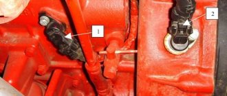
The switch (Fig. 2.), which controls the operation of the fan drive fluid coupling, is installed in the front part of the engine on the pipe so that its thermal power sensor 7 is located in the fluid flow supplied from the pump to the right bank of cylinders.
The switch has three fixed positions that determine the fan operating mode.
Automatic mode - the lever is set to position A. If the temperature of the coolant washing the thermal power sensor increases, the active mass located in its cylinder begins to melt and, increasing in volume, moves the sensor rod and ball 9.
At a liquid temperature of 85.90°C, ball 9 opens the oil channel in housing 5.
Oil from the main line of the engine through the channels in the switch body, the block and its front cover, tube 5 (see Fig. 3) and channels in the drive shaft enters the working cavity of the fluid coupling; in this case, the torque from the crankshaft is transmitted to the fan impeller.
When the coolant temperature is below 85°C, the ball, under the action of a return spring, closes the oil channel in the housing and the oil supply to the fluid coupling stops. In this case, the oil in the fluid coupling is drained through the hole in the casing 3 into the engine crankcase and the fan is turned off.
The fan is turned off - the lever is set to position O (Fig. 3), Oil is not supplied to the fluid coupling.
The impeller can rotate at a low frequency under the influence of friction forces arising during rotation in the bearings and fluid coupling cuffs.
The fan is constantly on - the lever is set to position P.
Oil is constantly supplied to the fluid coupling, regardless of the coolant temperature, and the fan rotates constantly at a frequency approximately equal to the crankshaft speed.
The main operating mode of the fluid coupling is automatic.
If the fluid coupling switch fails in automatic mode (characterized by engine overheating), it should be switched to permanent mode (set the switch lever to position A) and the switch malfunction should be eliminated as soon as possible.
Purpose of the fluid coupling
The most important component for ensuring effective engine cooling is the fluid coupling. Without it, KamAZ would have a continuously running cooling fan. Its meaning is to turn on the fan at the right time and then turn it off. After all, when the engine warms up, as well as during cold operation of the car, airflow is not needed at all.
The direct purpose of the fluid coupling is to transmit the torque of the engine crankshaft to the cooling fan at the right time. It also significantly dampens sudden changes in the operation of the crankshaft and serves as a good damper for fan drive.
How this unique cooling system unit works will be clear from its structure.
Operating principle of the fan fluid coupling
Now, after the internal structure of the fluid coupling has become clear, it is quite simple to understand how it all works. In automatic mode, the fluid coupling starts to move, and specifically, turns on the fan, when the coolant temperature rises to 83 o C or 86 o C. The fan, when turned on, blows on the radiator, thereby cooling the antifreeze and maintaining the optimal engine temperature.
When the antifreeze temperature drops, the fluid coupling switch is activated and it turns off the fan rotation. After this, it can only rotate passively, from the flow of incoming air due to the movement of the car (with the radiator shutters open).
It also now becomes clear how to ensure uninterrupted operation of the cooling fan. The easiest way is to set the “flag” of the fluid coupling switch to the “permanently open” position. The fan will constantly spin, since the oil will be in the fluid coupling all the time, and it will work in continuous mode as long as the engine crankshaft is spinning.
Maintenance and features of hydraulic coupling repair
The fan fluid coupling does not require special maintenance during operation; it can operate uninterruptedly throughout the entire service life of the engine. Only sometimes it may be necessary to adjust the response temperature of the switch-regulator; this is usually done by changing the thickness of the pack of washers under the thermal power sensor. And if the clutch breaks down, it is usually replaced together with the front motor cover.
Otherwise, the fluid coupling does not remind of itself and can serve for a long time, ensuring efficient operation of the cooling system.
KAMAZ hydraulic coupling design
The hydraulic coupling has a simple design. Its basis is a drive wheel, made in the form of a torus (“donut”) cut along the torus, and connected to the casing by means of several bolts. The casing itself is rigidly mounted on the drive shaft, which, in turn, is mounted on the rear wall of the coupling using a bearing. The drive shaft has a splined connection with the clutch drive shaft, which plays the role of an intermediary between the clutch and the crankshaft. From the outside, the annular pulley hub and the generator drive pulley itself are attached to the drive wheel.
Inside the casing there is a driven wheel, which is also a cut torus, with its flat side turned towards the drive wheel. The inner surfaces of both wheels, which have a toroidal shape, have blades located along the radius. The wheels are solid cast (with blades), which significantly increases their reliability and strength. There are 33 blades in the drive wheel of the clutch, and one less in the driven wheel. There is a small gap between the wheels, which is necessary for the supply and removal of oil. The space between the wheels and their internal surfaces turned towards each other form the working cavity of the hydraulic coupling.
A driven shaft is rigidly connected to the driven wheel, which is passed through a hole in the center of the drive wheel and through the pulley hub, and ends at the fan hub. The fan impeller is mounted on the hub using bolts and can be removed if necessary. The driven shaft rests on one bearing located inside the pulley hub, the second support is a bearing in the casing.
The entire assembly is mounted in the front cover of the cylinder block, the fluid coupling is located on the same axis with the engine crankshaft. The generator drive pulley and the fan hub extend from the outside; on the inside, the fluid coupling is closed by a cover in which a bearing is mounted that holds the drive shaft (therefore, this part is often called the fluid coupling bearing housing).
The regulator-switch also has a simple device. Its basis is a housing, inside of which there are oil channels, a spool-type valve and a thermal power sensor that changes its length depending on the temperature. This unit is installed on the right cylinder block, on the inlet pipe (through it, coolant is supplied to the water jacket, in this place it has a minimum temperature), while its oil channels are connected to the main oil line of the engine (which is directly connected to the discharge section of the oil pump ) and oil channels in the block and in the fluid coupling bearing housing.
The fluid coupling and the regulator-switch always work together and only in extreme cases require driver intervention.
How to identify a malfunction?
There are several factors to ensure long-term and trouble-free operation of the fluid coupling. KamAZ is very reliable, but there are some nuances. First of all, this is, of course, the working fluid coupling switch. In practice, most problems arise precisely because of its incorrect operation. This turns this part into a consumable item, along with engine filters.
The next factor will be the quality of the engine oil. If you have good all-season motor oil, the fluid coupling will operate normally and efficiently. KamAZ is not so demanding in everything, but not in this case. This must be taken into account when operating the car in winter.
It is also necessary to note the regular inspection of the engine cooling system for leaks. Any traces of coolant or oil must be removed promptly. The most insignificant leak without intervention can destroy the entire engine.
Deterioration in the performance of the fluid coupling can be easily determined by a decrease in the speed of the cooling fan. If it does not spin at all on a hot engine, the breakdown is obvious. It's good if the fan drive belt is simply worn out or loose. If it is a hydraulic coupling oil seal, KamAZ will require more labor-intensive work.
How does a viscous cooling fan coupling work?
In addition to all-wheel drive, other options for using viscous couplings are known - a cooling radiator fan can serve as one such example. The operation of such a device probably does not require much explanation. In cases where the thermostat circulates coolant in a large circle, it enters the radiator, and then the cooling fan must be turned on. At other times it should be turned off.
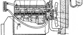
A viscous fan coupling helps achieve this operating mode. Its device is similar to the one above, only the body has additional containers for liquid and is equipped with a valve that ensures the flow of liquid. All this is shown in the figure.
When the engine is cold, the rotating discs force fluid through the open valve into a reserve reservoir. The clutch between the discs is poor, and the viscous coupling operates with strong slippage, there is no airflow to the radiator, and the engine warms up. When the thermostat directs coolant into the radiator for cooling, it heats up, warm air from it hits the bimetallic plate located in front of the viscous coupling body, it bends, and as a result, the valve hole is blocked.
The fluid has nowhere else to go, and it remains between the disks, its viscosity increases, slippage decreases, the fan impeller is blocked on the shaft, and air flows to the radiator to cool it. This leads to a decrease in the coolant temperature; accordingly, the temperature of the air entering the bimetallic plate decreases, it returns to its original position, the valve opens, and the liquid is squeezed out into the reserve chamber.
you will receive additional information about the operation of such a system. As for the ability to check the operation of the viscous fan coupling, the following video will help here
This procedure is quite simple and straightforward. It should only be noted that the viscous coupling is not disassembled; if it is faulty, it must only be replaced.
In the operation of a viscous coupling, such a characteristic of the liquid as viscosity is used. Thanks to its change, it becomes possible to implement different operating modes of devices, depending on external characteristics. We can talk about both creating all-wheel drive and cooling the radiator.
Most drivers are not familiar with the operating principle of the viscous cooling fan coupling. Therefore, if there are problems with this unit, mechanics begin to split hairs and reinvent the wheel. How to fix this part is legendary. Many people fall for them and end up with several more problems. Most often, drivers try to clamp the clutch discs.
To achieve a permanent connection between the fan and the shaft. To do this, holes are made in the viscous coupling and bolts are screwed into them. This works for some time, but after 100-200 km of travel they are cut off, which can lead to damage to the radiator. This is due to the structural features of this structural element.
Viscous coupling repair
If the engine begins to overheat, and the problem is related to the viscous coupling, you can try to repair it. The same applies to the drive connection coupling. The clutch is not officially repaired, the silicone fluid is not replaced, the bearing is not changed, etc.
However, in practice, it is quite possible to top up such fluid or replace the bearing, which often makes it possible to restore the functionality of the device. First you need to buy a suitable oil for the viscous coupling (can be original or an analogue) or a liquid for repairing universal type viscous couplings.
We also recommend reading the article on how to replace power steering fluid. From this article you will learn when to change the oil in the power steering, what kind of oil to fill in the power steering, and also how to do the replacement yourself.
Next you will need:
- Remove the clutch from the car;
- Disassemble the device;
- Lay the coupling horizontally and remove the pin under the plate with the spring;
- Find a hole to drain the liquid (if there is none, make it yourself);
- Using a syringe, pour about 15 ml of liquid into the coupling;
- The liquid is poured in small portions (the silicone should spread between the discs);
- Now the coupling can be assembled and put back;
If noise is heard when the viscous coupling operates, this indicates a bearing failure. To replace the viscous coupling bearing, the silicone fluid is first drained (then poured back in after replacement). Then the upper disk is removed, the bearing is removed with a puller, the flaring is ground off in parallel and a new bearing (closed type) is installed.
It is important to understand that you must be extremely careful when performing various operations. For example, even a slight deformation of the clutch disk will lead to complete failure of the device. Also, do not allow dust or dirt to get inside the device, do not remove special grease, etc.
Role in the internal combustion engine cooling system
A viscous coupling fan is installed on vehicles with a longitudinal engine (usually all-wheel drive and rear-wheel drive models). With this arrangement, it is most advisable to connect the radiator fan pulley to the water pump pulley. As you know, rotation of the water pump is transmitted by a service belt from the crankshaft pulley.
The disadvantage of this design is that the rotation speed of the fan impeller will always be proportional to the crankshaft speed. Such a device will result in the engine being excessively cooled at high speeds in cold air conditions, which will reduce its efficiency. In addition, the permanent connection of the impeller and the crankshaft pulley will increase mechanical friction losses, which will take away power and increase fuel consumption.
Device
The difference in the design of viscous fan couplings for Toyota, BMW, Mercedes, Audi. is minimal, since they are all designed and work according to the same principle.
A shaft with a connecting flange is attached to the cooling pump drive, so its rotation speed is always proportional to the crankshaft speed. A drive pulley, in turn, is attached to the shaft, which rotates in the working chamber. The working and backup chambers are separated by plates. The transition between chambers is only possible through inlet valves and return passages. Initially, the backup chamber is filled with special silicone oil. The drive pulley, or disk, as it is also called, has oblique teeth around its circumference, which, when rotated, allow the oil to be expelled back into the reserve chamber. The surface of the drive disks, like the dividing plates, has special ribs that turn the working chamber into a kind of network of labyrinths through which silicone oil circulates.
The coupling housing, to which the fan impeller is attached, is connected to the shaft (viscous coupling rotor) via a conventional ball bearing. The inlet valves are connected to a bimetallic plate, which is located in front of the viscous coupling housing. When heated, the plate expands, which leads to an increase in the flow area of the valves.
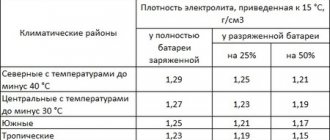
Properties of silicone oil
The main feature of silicone fluid used in viscous fan couplings is heat resistance and viscosity stability. As temperature changes, the oil changes its viscosity only slightly.
Some sources indicate that with increasing temperature, the oil expands, which provokes viscous engagement of the drive disk with the viscous coupling body. This understanding of the operating principle of a viscous cooling fan coupling is false and most likely arose due to a comparison of the viscous fan coupling with viscous couplings of transfer cases of all-wheel drive vehicles. Viscous differential couplings use a dilatant fluid whose viscosity is highly dependent on the rate of shear strain.
Principle of operation
When the working chamber is not filled with oil, the drive disk rotates freely in the working chamber. A small amount of oil is still present, but the coefficient of adhesion between the drive pulley and the viscous coupling housing is minimal, so as the engine speed increases, the rotation speed of the impeller does not increase.
The process of warming up the engine and increasing the temperature of the antifreeze in the radiator is accompanied by heating of the bimetallic plate. When heated, the plate expands, which leads to the opening of the inlet valve and an increase in the amount of working fluid penetrating from the reserve into the working chamber. The friction that occurs between the drive disk and the separating plates leads to an increase in the speed of rotation of the housing and the fan impeller.
When the engine needs maximum cooling, the bimetallic strip is bent to provide maximum flow area to the intake valves. In this case, the difference in the rotation speed of the shaft and the viscous coupling housing is minimal, so an increase in the crankshaft speed leads to an almost equivalent increase in the rotation speed of the fan impeller.
Typical viscous coupling malfunctions
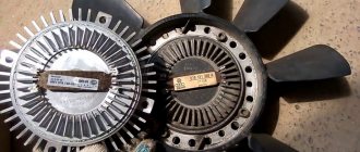
The mechanism can last a long time - up to 500,000 km. After this period it has to be replaced due to wear and tear. Plates made of bimetal may break.
A common malfunction is fluid leakage from the housing. The mechanism will have to be dismantled and disassembled in order to top up. Since the liquid has a high degree of viscosity, it will take some time to completely fill the plane. Topping up should be done without haste.
Bearings also often fail. When this happens, a characteristic noise is heard in the area of the mechanism. To remove the bearing, use a special puller. Pullers are universal and “tailored” for a specific car. After changing the bearing, it is worth changing the silicone fluid.
Typical malfunctions include “beating” of the fan blades and their destruction.
How the device works
It was invented in the USA in 1917 by engineer Melvin Severn. This product did not immediately find its application, so it was not recognized for a long time. In 1964, a viscous coupling was installed in the Interceptor FF, where it acted as an automatic differential lock. Only in 1965 did this mechanism take its place.
The main cause of problems with this setup was a loose or broken fan belt. The V-belt drove the fan through a pulley system by friction, therefore, as the belt stretched through wear, it could begin to slip. The warning lights are overheating while driving because the fan and water pump are not spinning at the correct speed.
If the belt had also driven the alternator, the final warning on older cars would have been a red ignition light indicating a failure to charge the system, but by then the belt may have been loose. The good news is that if you own an older car with this type of cooling fan, the setup is simple. One of the pulleys will have some form of adjustable mounting. It is usually found on the generator or alternator where there is a slot instead of a bolt hole for a mounting bolt.
A viscous coupling is a device that is responsible for rotating a special fan that cools the system thanks to a special liquid. It looks like a round mechanism made of a silicone base and filled with a lubricant. The viscous coupling ensures smooth fan control.
There are flat disks inside the product body. Some of them are connected to the drive shaft, while others are connected to the driven shaft. There are various protrusions and holes on their surface. Design features place these elements in close proximity to each other. The silicone liquid located inside tends to thicken with strong stirring. It also expands when heated, so it creates a lot of pressure on the disks when the engine is running and compresses them together.
How does a viscous cooling fan coupling work?
This allows the unit to rotate while the remaining mounting bolts are loose. When moving the generator away from the engine, tighten the belt and it should be adjusted until the belt is deflected downwards by 12mm at its longest stroke. When performing any kind of fan repair, it is wise to replace the fan belt or at least have it properly inspected for wear and cracks. Even if the old belt isn't too worn out, replacing it will give you a handy spare that can be very useful.
Features of the mechanism
At first glance, the operating principle of a viscous cooling fan coupling seems complicated, but it is not. The movable one is driven into rotation and transfers its energy to the clutch. This makes its silicone base softer and more viscous. The clutch begins to block, causing the second disk with the fan to rotate.
Purpose and role of the UAZ fluid coupling
A new belt will stretch considerably after you first insert it, especially if it controls a lot of auxiliary equipment, so it should be checked after the first few kilometers. A simple fan with a metal blade requires a little extra attention, but if you're working in this area of the car, it's worth giving it a few checks. With most older cars you will need to remove the radiator to check that the fan bolts are secure, usually not enough room to slip into a wrench or small socket with the radiator in place. Almost every engine has a viscous coupling.
This is due to the importance of its functions and the quality of the device, because it is at a fairly high level
The viscous coupling perfectly implements a safety mechanism: when a person, through his own negligence, puts his hand into the moving element, he will stop to prevent injury
Selection and replacement of couplings
As for replacement, you need to remove the old device and put a new one in its place, and then check its functionality. In practice, more difficulties arise not with the replacement itself, but with the selection of spare parts.
For replacement, it is important to select a viscous cooling fan coupling or drive connection coupling of proper quality. To do this, you will need to find out the code of the original spare part, after which you can determine the available analogues in catalogs. To accurately select a spare part, you will also need the vehicle’s VIN, make, model, year of manufacture, etc.
We also recommend reading the article about why the engine overheats. From this article you will learn about the main causes of engine overheating, as well as available diagnostic and repair methods.
Having figured out which part is needed, you should also pay attention to the manufacturer. Taking into account the fact that viscous couplings are produced by only a few companies, it is optimal to choose from the leading manufacturers: Hella, Mobis, Beru, Meyle, Febi. As a rule, the same manufacturers also produce other parts (cooling radiators, thermostats, suspension units, etc.).
Fluid coupling is the “heart” of the cooling system
How does the cooling system work on KAMAZ?
Engine power directly depends on the functioning of the cooling system
The engine on a KAMAZ can heat up to 220°C, so timely reduction of temperature is extremely important. This process is a closed system with forced circulation of special antifreeze
Circulation is provided by a centrifugal pump. A thermostat is used to constantly maintain the temperature of the antifreeze. A distinctive feature of trucks is the presence of two thermostats in parallel. When overheating, the thermostat directs antifreeze to the radiator. Here the circulating circle is completed, and the liquid is cooled to the optimal rate. A special feature of the radiator on KAMAZ is the presence of blinds. Blinds control the flow of air masses passing through the grille. The total capacity of the cooling system is 25 liters.
In hot weather or at maximum speed, the radiator may not cope with its task. Then another important part comes to the rescue - the fan. It regulates the speed of antifreeze and blows through the radiator, ensuring the outflow of excess heat. The fan makes possible trouble-free operation of the system at any time of the year and at maximum load. The “heart” of the fan is a fluid coupling, which ensures excellent fan operation.
Purpose of the fluid coupling
We study the structure and principle of operation of the fluid coupling
To understand the principle by which a fluid coupling works, you need to study its components. The base consists of two wheels: driving and driven. They spin on a shaft using bearings. The drive wheel is inextricably linked to the crankshaft, and the driven wheel is connected to the driven shaft. The principle of operation is quite simple. The driven shaft drives the fan, which is the main function of the device. There are radial vanes inside the wheels. The structure of the wheels is solid, which ensures their reliability and strength. The space between the blades is the working cavity of the part into which oil is supplied. The fan speed depends on the amount of oil. The structure is sealed by two rubber cuffs.
Fluid coupling diagnostics and repair
The weakest link in the device is the switch. Most often, it is this component that fails and entails failure of the clutch as a whole. The nuances of repairing the part are shown in the video:
If the service life of the unit has come to an end, replace the coupling with a new one. But remember that replacing the coupling separately is a complex and time-consuming operation. It is much easier to change the entire assembly with the front cover of the unit.
Can't find the cause of the problem? Then the unit must be dismantled and disassembled. We'll tell you more later.
Self-removal of the hydraulic coupling
— remove the oil pan and radiators;
— remove the oil filter;
— lift the engine and remove the front cover along with the fluid coupling.
After dismantling, blow out all channels for the supply of working fluid and check the torsion of the wheels. Carry out repairs using a specially designed device. A beam crane or suspension will do. Wash contaminated parts with gasoline. Next, the installation procedure is carried out in reverse order. After installing the element in its original place, diagnose all connections, and then just start the fluid coupling.
Operating rules and troubleshooting
The fluid coupling does not require special maintenance, but monitoring and checking its condition will extend its service life. Routine inspection and proper oil changes will help prevent malfunctions. The check should be carried out even if there are no current problems. Monitor the quality of the engine oil, it directly affects the condition of all components of the clutch
Please note that there should be no leaks in the system. Even the smallest leak can lead to engine failure
Ordinary water can act as a coolant in the summer, but for the winter period you need properly selected antifreeze or antifreeze.
A common cause of breakdowns is a malfunction of the fluid coupling switch; special attention should be paid to this part during inspection. Timely replacement or repair of a faulty part will ensure efficient operation of the unit as a whole.
When selecting components, do not look for cheap analogues, choose high-quality original spare parts. When replacing the hydraulic coupling completely, we recommend replacing the entire set with the front cover of the cylinder block. With proper supervision and care, the structure will serve effectively throughout its entire service life.
Source
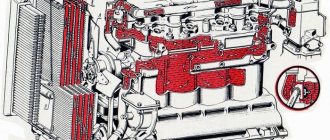
A general view of the cooling system of KAMAZ power units
Diesel engines of Kama trucks are equipped with a dual-circuit liquid cooling system built according to a traditional design. It consists of a water jacket (a system of cavities and channels) in the cylinder block and in the cylinder head, a liquid pump (pump), several thermostats, a radiator, a piping system and various sensors. This system also includes a fan that removes excess heat from the radiator at certain engine operating modes.
The functioning of the system is as follows. When you start the engine, the pump immediately starts working, which circulates antifreeze in the first (small) circuit, bypassing the radiator. When the power plant warms up, the thermostat is activated, which opens the path of coolant to the radiator, which ensures cooling and maintains a certain temperature of the engine.
However, the radiator does not always work efficiently - at high speeds, as well as in hot weather, the removal of excess heat into the atmosphere is significantly worse, which can lead to overheating and engine failure. The fan included in the cooling system solves the problem - it creates an air flow that blows over the radiator, removing excess heat. Without a fan, normal operation of the car, especially in the warm season, would be impossible.
The operation of the fan is ensured by a special unit - the fan drive clutch. Until recently, KAMAZ vehicles used exclusively a hydraulic coupling (fluid coupling) paired with a regulator-switch. Today, Kama trucks are increasingly equipped with simpler viscous couplings (viscous couplings). Here we will pay attention only to the fluid coupling - a solution that is still popular and has a number of advantages over the viscous coupling.
Selecting a new device
Of course, an important search parameter is the manufacturer of the final product. Many car enthusiasts justifiably do not trust the products of packaging companies. In the case of viscous couplings, you can even take products from such companies, since, in fact, they are produced by a limited number of companies, which are also suppliers to the conveyors of large automobile concerns and whose products are even sold by packers
It is worth paying attention to the products of these companies:
Very good solutions can be found in the catalogs of Meyle and Febi (Germany). The Polish and Turkish analogs that appeared relatively recently did not perform so well. As a rule, reputable manufacturers of viscous couplings simultaneously produce radiators, fasteners and some pipeline elements. If you are confident in a certain radiator manufacturer, it is worth looking in its catalogs for the viscous coupling you need.
Prevention and Maintenance
The fluid coupling drive ensures correct and uninterrupted operation for quite a long time. KamAZ generally has a good margin of reliability. And in order for this to last as long as possible, there is no need for special maintenance. Prevention of malfunctions consists of general regular inspection, scheduled maintenance with high-quality replacement of oils and other technical fluids.
Also, when operating and servicing a fluid coupling, you should always pay attention to its weak points - the switch. Timely replacement of a faulty switch can greatly facilitate the operation of the unit as a whole.
Main causes of malfunction
If you carry out timely routine maintenance of the viscous coupling, its service life is at least 200,000 kilometers. Considering that most of the cars on which such drives are installed have a significant mileage, the owners of these cars have encountered problems with viscous couplings more than once.
The main causes of the malfunction include:
- natural wear and tear;
- changing the parameters of bimetallic plates;
- bearing wear;
- fan impeller beating (partial destruction of the impeller);
- gel leakage, untimely filling, change in gel structure;
- mechanical damage.
Also, premature failure of work may be accompanied by clogging of the radiator cell blowing area and contamination of the design of the coupling itself.
Advantages of a fluid coupling
If we consider other types of couplings in the fan drive, namely electric and viscous couplings, the fluid coupling has clear advantages.
- There is no entire electrical circuit to control and monitor the operation of the unit.
- Higher design reliability, which increases uptime during engine operation.
- Turning the fan on and off with a fluid coupling is the fastest.
All the obvious advantages of the fluid coupling are noticeably worsened by the not most reliable element of the system - its switch. In practice, different methods are used to increase overall reliability. One of these is the use of a switch from Ural-4320.
General information about viscous coupling
One of the most important components of a car is a rotating viscous coupling, inside of which there are alternating perforated plates with a viscous liquid. There are many types of such structures on sale with different operating properties and features, but the general principle of their operation remains the same.
Each viscous coupling consists of a number of internal plates that are capable of rotating on the drive shaft, as well as external elements connected on the driven shaft at a specified interval. All components are interconnected and evenly distributed throughout the body.
This part differs from a fluid coupling and a torque converter in its specific operating principle. First of all, another method of transmitting torque is involved here, which is based on the influence of a special viscous fluid located in the internal space of the structure.
The first mention of viscous coupling appeared in 1917
, but in those days it failed to become widespread, because did not have many of the current advantages. Only in 1964 the product was significantly improved and began to be put on mass sale. In the 60s of the last century, these inventions began to appear in cross-axle differentials on all-wheel drive passenger cars.
Features and weaknesses of the fluid coupling
The fluid coupling is a rather complex unit, and it may seem that it is not a very reliable design. But in practice, the fluid coupling itself practically does not break. Its reliability is exceptionally high. The weak point in the system for transmitting torque from the crankshaft is the inclusion of the fluid coupling. KamAZ has a rather weak fluid coupling switch. It is the element that can fail the entire cooling system of the car.
The seals and bearings in the fluid coupling itself can theoretically wear out. But these components are selected based on typical loads, plus a certain margin of safety. For them to fail there must be an unplanned impact. In cases where the vehicle operates smoothly and with regular maintenance, the fluid coupling can operate without repair or replacement.
Functionality check
Viscous couplings of radiators are not so difficult to check. The operating manuals indicate that fan rotation should be checked first on a cold and then on a hot engine. At the same time, on a hot engine, when the engine is revved up, the rotation speed seriously increases, while on a cold engine it does not. The “folk” method of checking is very good, since it also involves caring for the engine cooling system. Here's what to do:
- Without starting the engine, try to rotate the fan blades with your hand or an improvised object. They should spin with little resistance, but without inertia;
- Start the engine and listen. In the first seconds, the motorist should hear a slight noise, which will gradually subside;
- After warming up the engine slightly, try to stop the blades with a folded sheet of paper. They must stop, but with a clearly noticeable effort;
- Remove the viscous coupling and warm it up strongly. Optionally, in boiling water. After this, the clutch should resist rotation. If it turns, there is practically no silicone liquid left inside. It is also recommended to remove the engine cooling radiator and wash it;
- Check the longitudinal play of the device. If there is one, the coupling must be repaired.
Please note that if one of the verification stages has not been passed, there is no point in going further along the list. However, remove the clutch and clean the radiator
It always makes sense, especially if you do this after the summer period, when the honeycombs become clogged with fluff, dirt and dust.
How to check a viscous coupling
The performance of the viscous fan coupling must be checked on a cold and hot power unit. This is evidenced by operational manuals for vehicle repairs. When the engine is cold, re-gassing will not change the clutch rotation speed. In the case of a hot engine, this figure will increase significantly.
It is also necessary to check the longitudinal play; if it is detected, work will have to be done to eliminate it. The presence of extraneous sounds during clutch rotation will indicate a bearing malfunction.
Main causes of malfunction
The mechanism can fail for several reasons. We have identified the main and most common:
- the use of tires of different sizes, which also have different levels of wear;
- fluid leakage from the coupling;
- wear of parts as a result of intensive use, exposure to aggressive factors and high temperatures;
- incorrect alignment of the drive mechanism;
- loss of properties of the bimetallic sensor, which can occur as a result of surface oxidation and jamming of the coupling;
- faulty bearing condition.
Intake viscous coupling of an Infiniti car
Symptoms of a problem
The first and main sign that may indicate a faulty viscous coupling is excessive heating of the motor. This situation may occur as a result of a liquid leak or the failure of the bimetric plate to operate in a timely manner. The motor temperature rises, and the fan does not work at all or operates at low speeds, therefore, the unit is not cooled.
It also happens that when the engine is cold, the fan rotates at full speed. This situation may arise due to a damaged gel, breakdown of a number of mechanism components, or transformation of the lubricant into a solid substance.
What can a faulty viscous coupling cause?
The working reserve of a viscous coupling is on average 200 thousand km. After this, the mechanism requires increased attention. It is necessary to constantly monitor the moment of its operation, especially in the summer. It is also necessary to check the operating temperature of the engine in traffic jams. If values close to critical are observed, then you will have to seriously work on the viscous coupling. A new part costs a lot, and finding the right model is often not possible. That's why many car owners decide to install an electrical system. In any case, this situation cannot be ignored, since you may encounter the following troubles:
- motor overheating;
- reduced pump life;
- increase in fuel consumption.