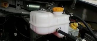
Monitoring the liquid level in the cooling system
With the engine cool, open the heater and radiator filler pipe plugs.
With the cabin heater valve unscrewed, the required fluid level should be equal to the top edge of the radiator cooling pipes. The coolant used is low-freezing concentrated Tosol-A (a poisonous substance), diluted with clean and soft water. The proportions depend on the climate zone in which the machine is used (table).
Wheels and tires
► Malfunction: Intense uneven wear of the tread pattern
Remedy: Incorrect alignment of steered wheels
Probable Cause: Adjust wheel alignment
Elimination method: The adjustment of the wheel hub bearings and steering knuckle bearings is incorrect
Probable Cause: Adjust bearings
Remedy: Worn steering rod joint parts
Probable cause: Replace worn parts with new ones.
Remedy: Large radial or lateral wheel runout
Probable cause: Replace wheels with increased radial or lateral runout
Method of elimination: Sharp braking or starting, driving with low or very high internal tire pressure, overloading the tires with the weight of the load.
Probable Cause: Follow the rules and use sound driving techniques.
Remedy: Strictly observe tire inflation pressure standards and do not overload tires.
Features of draining coolant from the cooling system and heater
To remove liquid from the system, you need to place the machine on a horizontal surface or platform tilted forward. Open the four valves located on the heater boiler 3 (Fig. 1), the heater pump unit 5, the lower radiator tank 4, and the lower pipe 2 of the engine water pump. The heating valve, filler pipe and radiator neck plugs must be open.
If one of the taps is clogged, clean it with wire. To drain the fluid from the expansion tank, lift it. When water is used in the cooling system, the heater pump unit must be turned on for 10-15 seconds to remove water from the pump.
It is strictly prohibited to start the engine without coolant to avoid overheating.
Features of filling the cooling system with low-freezing liquid
The coolant drain valves must be closed. The filler pipe plug 1 of the heater must be opened, then the cabin heater tap must be opened, then the cooling system must be filled through the radiator filler neck. You should make sure it is tight.
"Ural"-4320, 5557: additional power take-off box
Power is taken from the input shaft of the machine's transfer case through a movable clutch. The power take-off is designed to drive the winch, as well as other devices and installations.
The additional power take-off box can operate in any gear, including neutral. To lubricate the shaft and gear bearings, a plunger pump is provided in the additional power take-off box. The pump includes a piston with a discharge valve, a safety valve and a housing. A piston with a connecting rod is located on the eccentric of the shaft. When the eccentric rotates, the piston moves forward.
To avoid excessive pressure when the rotation speed increases, the suction valve is made of a differential type and has a cylindrical spring. Oil is taken through a tube, which is connected to the oil bath of the transfer case of the machine, and supplied from the pump to the gear bearings through channels made in the primary shaft of the transfer case and the shaft. Some of the oil passes through the gaps, and thus the shaft bearings are lubricated.
In the driver's cabin, at the bottom right of the instrument panel, there is a control valve for remote activation of the additional power take-off box of the Ural-4320 vehicle. The faucet is mounted on a bracket. The control valve lever in the “off” position is fixed with a screw located on the valve bracket.
If the auxiliary power take-off box operates for a long time, there should not be excessive heating of the bearings of the power take-off shafts and the transfer case. If the heating is increased, this indicates a breakdown of the oil pump.
To check the operation of the pump, you should:
- tighten the parking brake handle all the way;
- Move the transfer case gear shift handle to the neutral position;
- turn off the winch; to do this, move the handle on the right side member of the frame down;
- Unscrew the plug in the pump housing;
- start the engine, turn on the additional power take-off box of the Ural-4320, 5557 car, turn on one of the gears,
- identify pump failure by closing the plug hole with your finger.
If the pump is working properly, then a pulsation is felt in the hole under the plug. It is prohibited to operate if the pump is faulty.
Source
Features of adjusting the tension of drive belts
Check the degree of tension of the drive belts of the water pump, drive fluid coupling, generator and fan by pressing the middle of the largest belt branch with a force of 4 kgf (Fig. 3). The belt deflection should not be more than 15-22 mm. If they sag by a smaller or larger amount, their tension needs to be adjusted.
Adjustment of the tension of the drive belts of water pump 3 and generator 1 is performed by changing the position of the generator relative to the axis of its mounting. This is done by releasing nuts 7 and 2.
The tension of the hydraulic coupling drive belts 6 is adjusted by the tensioning device 4 by loosening the nut 5 securing the lever and moving it around the axis with the pulley, inserting the knob into the hole at the end of the lever.
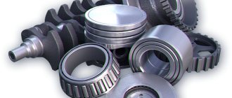
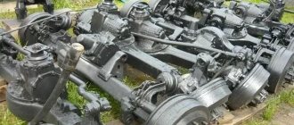
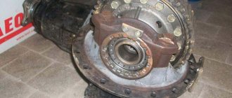
Drive axles
► Fault: Increased bridge noise
Probable cause: Displacement of the contact patch of the bevel gears to the edge of the narrow end of the tooth
Remedy: Adjust the engagement according to the contact patch
Probable cause: Gear bearing clearance
Remedy: Restore bearing preload
Probable cause: Wear, damage to the working surface of the gear teeth
Remedy: Replace gears
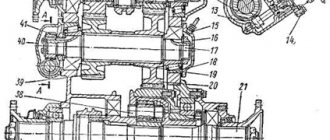
Features of regulating fan operating modes
When valve 4 (Fig. 2) of the fluid coupling switch is in position “B” (mark on the switch), the temperature of the coolant in the system remains in the range of 80-95°C.
The fan will be turned off when the tap is moved to the “O” position. At the same time, it can rotate at a low frequency. When the tap is set to the “P” position, the fan is constantly running (blocked). The use of such a mode is justified only for a short time in case of probable malfunctions of the fluid coupling or its switch.
If the temperature of the cooling liquid in the system rises by more than 105°C while the fan is running, it is necessary to adjust the stroke of the switch rod by moving the adjusting washers 1. In the new switch, the washers are located above the thermal power sensor 3. If the thermal conditions change, they should be moved sequentially under the sensor. After the next adjustment or moving the washers, the thermal power sensor must be replaced. The tightening torque of nut 2 fixing the sensor should not be higher than 2-2.3 kgf.m.
"Ural"-4320, 5557: power take-off
The car's power take-off (PTO) is single-stage.
Fixed on the right side to the gearbox housing. Designed to drive auxiliary mechanisms. “Urals” are equipped with two types of PTOs: with a flange and a pump. The PTO should be turned on when the air pressure in the pneumatic system reaches 500 kPa (5 kgf/cm2). The clutch must be disengaged. Between the PTO and the flanges of the Ural-4320 gearbox housings there are adjusting gaskets, with the help of which the lateral clearance is adjusted based on the noise in the meshing of the gears. If it is necessary to replace the gaskets, their thickness must be maintained.
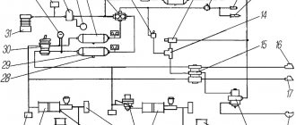
The power take-off can be controlled remotely. The control is pneumatic, which includes a control valve, a starting device, and air ducts. To remotely turn on the PTO, there is a control valve mounted on a bracket to the right of the driver in the cockpit at the bottom of the dashboard. If the PTO is disabled, then the lever is at the top and the rod is in the right position. Under the action of a spring, the valve is pressed against the seat and air does not flow through the tap.
When the power take-off is turned on, the crane lever is moved to the lower position. The rod moving to the extreme left puts pressure on the valve and moves it away from the seat. Compressed air flows through air ducts into the diaphragm chamber of the switching device. Through the rod and fork, the diaphragm engages the driven shaft gear with the drive gear.
When the PTO is turned off, the valve lever is in the upper position. Under the action of the spring, the rod takes the extreme right position, moving away from the valve. The chamber of the vehicle gearbox switching device communicates with the atmosphere, air comes out of the chamber, and under the influence of a spring, the rod and fork disengage the driven shaft gear from the drive gear. In parallel with the release of air into the atmosphere, the valve is pressed against the seat under spring pressure and separates the valve openings (inlet and outlet).
Assembly sequence of the ZIL-375 water motor pump
Press the bearings onto the shaft. Place a spacer sleeve between them. Place the reflector on the shaft and secure it with a spring ring.
Insert the rubber seal assembled with a spring and a washer into the impeller socket. Pre-treat the ends of the washer with a thin layer of graphite lubricant. Press the clip using a mandrel. Place grease into the bearing housing and press the shaft with bearings into the housing. Insert the thrust retaining ring of the front bearing into the groove of the housing. Install the impeller on the shaft, secure it with a screw and thrust washer. When assembling, keep an eye on the end clearance between the impeller and the pump and bearing housings.
Place the bearing housing with the gasket on the studs of the water pump housing. Secure it with nuts. It is recommended to place the studs on the sealing material. Insert a key into the groove, put a split conical bushing on the shaft and install the hub. When installing the key into the hub, place a stop under the cantilever end of the shaft. Place the pulley on the hub and secure it with bolts. Place the bushing, bearings, and spring ring in the fan pulley hub. Secure the pulley with a nut, washer, and cotter pin.
The process of disassembling and assembling the ZIL-375YA4 water motor pump is performed in a similar way.
Dismantling the ZIL-375 water motor pump
To replace the oil seal parts, you need:
- Separate the pump housings and bearings. To make it easier to unscrew the nuts, first remove the pulleys;
- Remove the impeller from the shaft using a puller, remove the race from the impeller, and remove the oil seal parts.
If there is a need to replace the bearings, press the pump shaft out of the bearing housing, then remove the spring ring from the shaft, remove the water deflector, compress the bearings, and release the spacer sleeve.
After disassembling, check the parts for integrity and replace those that have become unusable.
Radiator
When used, the radiator may show faults in the cooling plates and tubes, cracks in the tanks, and sidewalls at the fixation points. To detect the location of the leak, the radiator is checked with compressed air in a container of water. External tubes can be soldered without disassembling the radiator. Internal tubes that are not accessible for soldering are plugged, but not more than ten percent of the total. Cracks in radiator tanks are sealed at the soldering points, and throughout the tank they are sealed by soldering patches of sheet-thick brass. After repair, the radiator must be checked for leaks.
Return to list of articles>>>