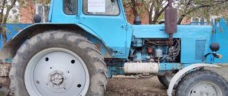
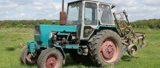
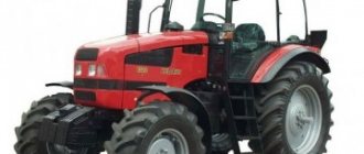
The concept of “tractor Belarus” has long become a household name among the people, personifying a tireless and trouble-free worker. With all the diversity of the Minsk Tractor Plant model range, this reputation is attached to one of the basic models of the enterprise - the MTZ-80 tractor and its all-wheel drive modification MTZ-82, which does not differ in appearance. The main advantages of the model, confirmed by a 40-year history of operation, are versatility, simplicity and reliability.
The scope of application of the tractor includes both agricultural work and general purpose activities. For the MTZ-80 and MTZ-82 models, water-cooled diesel engines D-240, D-243, D-245 are used, the engine power is 80 hp. The number of mechanisms, components, tools and devices integrated with the design is more than 200 different options.
The versatility of the tractor is largely due to the successful design of the transmission, which ensures its operation in different modes and operating conditions, with different types of hitch. It consists of a clutch, gearbox, rear drive axle with final drive and differential.
Gearbox and PTO control Belarus MTZ-82.1
The Belarus MTZ-82.1, 80.1, 82.2 tractors with the basic configuration are equipped with a mechanical stepwise dual-range gearbox, with one range and gear shift lever located under the operator’s right hand with a mechanical reduction gearbox (18F+4R).
It is possible to install transmissions with the following configurations:
— with a manual transmission and synchronized reduction gearbox (18F+4R); — with a manual transmission and reverse gearbox (9F+9R).
Gear shifting in a transmission with a manual gearbox and a mechanical or synchronized reduction gearbox.
The controls for a manual transmission with a mechanical or synchronized reduction gear are shown in the figure.
Fig. 15. Control of checkpoint Belarus MTZ-82-1, 80-1, 82-2
1 – diagram of switching stages of the reduction gearbox; 2 – reduction gear control lever; 3 – range and gear shift lever; 4 – scheme for switching ranges and gears.
Gear shifting is carried out by two levers: the transmission range and gear shift lever and the reduction gear control lever 2.
The selection of the required ranges, gears and stages of the reduction gear (the decelerating stage is the “turtle” symbol, the accelerating stage is the “hare” symbol) is made in accordance with switching patterns 4 and 1.
Switching ranges and gears is done with one lever 3, and first the range (1st or 2nd) is turned on, then the lever is moved to the “N” position, and the selected gear is engaged.
The control lever of the mechanical reduction gearbox 2 must be in the on (fixed) position during tractor operation: backward - accelerating stage ("hare"), or forward - decelerating stage ("turtle").
The control lever for synchronized reduction gearbox 2 must be in the on (fixed) position while the tractor is operating: backward - decelerating stage ("turtle"), or forward - accelerating stage ("hare").
It is possible to hold the reduction gear lever in the neutral (middle non-fixed) position to facilitate engine starting at low temperatures.
Gear shifting in a gearbox transmission with a reverse gearbox
The control elements of the Belarus MTZ-82.1, 80.1 gearbox with a reverse gearbox are shown in the figure.
Fig. 16. Gearbox control
1 – diagram of switching stages of the reverse gearbox; 2 – reverse gear control lever; 3 – range and gear shift lever; 4 – scheme for switching ranges and gears.
Gear shifting is carried out by two levers: the range and gear shift lever and the reverse gear control lever 2.
The selection of the required ranges, gears and reverse gear stages (forward stage - “forward” symbol, reverse stage – “backward” symbol) is made in accordance with switching patterns 4 and 1.
Switching ranges and gears is done with one lever 3, and first the range (1st or 2nd) is turned on, then the lever is moved to the “N” position, and the selected gear is engaged.
The reverse gear control lever 2 must be in the on (fixed) position while the tractor is operating: forward – forward gear (“forward”), or backward – reverse gear (“backward”). It is possible to hold the reverse gear lever in the neutral (middle non-fixed) position to facilitate engine starting at low temperatures.
PTO control
On Belarus MTZ-82.1, 80.1 tractors, a rear power take-off shaft is installed as standard. A side semi-independent PTO can also be installed.
Rear PTO control
Handle for switching rear PTO from independent to synchronous drive
When moving handle 11 to the extreme left position (along the path of the tractor), the synchronous drive is activated, to the extreme right - independent, to the middle - the “neutral” position.
Engaging the rear power take-off
Engaging the rear PTO Belarus MTZ-82-1, 80-1 is possible only if handle 11 is set to the “synchronous drive is on” position or to the “independent drive is on” position. In the “neutral” position, the rear PTO does not work.
The rear PTO 5 engagement lever has two positions:
— when lever 5 moves from the extreme forward position to the extreme rear position, the rear shaft is engaged;
— when lever 5 is moved from the rearmost position to the frontmost position, the rear shaft is switched off.
It is recommended to turn the rear PTO on and off while the engine is running. In the figure, lever 1 is set to the “off” position.
Fig. 17. Rear PTO connection diagram Belarus MTZ-82.1, 80.1
1 – rear PTO engagement lever; 2 – instruction plate for rear PTO control.
Switch for two-speed independent rear PTO drive
The driver of the independent PTO 2 drive has two positions:
– I – 540 min-1) – extreme, clockwise; - II - 1000-1) - extreme counterclockwise.
To set the desired rotation speed, unscrew bolt 1 by one turn, turn driver 2 to position “I” or “II” and tighten bolt 1.
Fig. 17A. Switching rotation speed (transmission bottom view)
Operation of Belarus MTZ-82.1, 80.1 tractors without using a rear PTO
When operating the tractor without using the rear PTO, the switch lever for the independent two-speed shaft drive must be set to the 540 min-1 position, the rear PTO switch handle from independent to synchronous drive must be set to the neutral position, and the rear PTO engagement lever must be set to the “off” position.
Adjustment procedure
The need to install injection arises when replacing a high-pressure fuel pump (HPF) or installing it after repair, as well as after repairing the piston group of a diesel engine. The adjustment is carried out provided that the fuel equipment, injection pump and the adjusted gas distribution mechanism of the diesel engine are in good working order. The installation process consists of the sequential operations described below.
Installing the first cylinder on the compression stroke
On the right side, in the direction of travel of the machine, in the wall of the engine mounting to the clutch housing, above the longitudinal beam of the tractor frame near the oil filler neck, there is an installation dipstick. With its short threaded part it is screwed into the mounting wall and with its long threadless part it is installed outside. If it is necessary to install the first cylinder in the “compression” stroke position, the dipstick is installed in the hole, resting its long part against the engine flywheel. Slowly turning the diesel crankshaft, find a position in which the probe will fall into the hole on the flywheel and enter the body of the part completely by 4-5 cm. It is important not to confuse the installation hole with the technological, balancing drillings of the flywheel, which are much smaller in depth. The found position corresponds to an advance of 26 ̊ before the piston of the first or fourth cylinder approaches TDC. This position corresponds to the technical requirements of D 240 for setting the start of fuel injection into the cylinder during the “compression” stroke. To determine which of the cylinders in the first or fourth the “compression” stroke has begun, you need to remove the valve cover. A pair of closed valves will indicate in which of the two cylinders (first or fourth) the “compression” stroke has begun.
To change the position of cylinders 1 and 4 during the “compression” and “exhaust” strokes, you need to rotate the crankshaft 360 ̊ until the hole coincides with the dipstick again. In practice, it does not matter for which cylinder the injection timing is set to 1 or 4.
Disconnecting the pump drive
To establish synchronization of the engine and fuel injection pump operating cycles, you need to understand that the pump drive connecting through the engine timing gears must be disconnected. The drive is connected by connecting the holes of the pump drive gear 4 with the adjusting holes of a special washer 5 along the perimeter through a splined bushing fixed to the pump shaft. Access to the drive is achieved by opening the front cover 8 of the pump. To disconnect, unscrew two fastening bolts 3 with strip 7 and remove the adjusting washer from the splined sleeve. In this position, the rotation of the shaft cranks will not be transmitted through the camshaft gear drive to the pump shaft 6 .
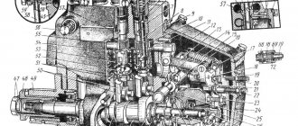
Momentoscope installation
After identifying the cylinder in the “compression” stroke and disconnecting the drive on the fuel pump, install a torque scope on the corresponding supply section of the pump instead of the high pressure pipeline connecting the section to the cylinder injector. To more accurately determine the beginning of the injection moment, set the manual fuel supply lever to the maximum position. To determine the moment of injection, if necessary, pump the fuel equipment with a manual pump pump, removing air from the system.
The momentoscope is a glass or plastic transparent tube, which is screwed onto the fitting of the fuel pump section with its threaded part.
Determining and setting the timing of fuel supply
By turning the injection pump camshaft clockwise and observing the fuel level in the device tube, you need to determine the position of the pump shaft at the moment fuel supply begins in this section. The moment the supply begins will be the position at which the fuel level in the device tube begins to rise, shifting as a result of the start of the supply cycle, running the injection pump shaft cam onto the plunger pusher of the corresponding section. It is very important to determine the beginning of this cycle by observing the fuel level in the momentoscope.
Experienced tractor drivers and repairmen establish the timing of fuel supply by observing the hole in the recess of the section fitting. The feeding moment is determined when the fitting recess begins to be filled with fuel.
Setting the position of the pump drive shim
Having determined the moment of the start of injection on the section by the position of the injection pump shaft, connect the pump drive by installing a splined adjusting washer on the splined bushing. The fastening bolts with the strip are screwed into the most aligned holes of the washer and the flange of the pump drive gear. In this case, the bolts should fit freely without snagging. Then install the pump cover by tightening the three bolts around the perimeter of the cover. The axial clearance of the drive gear is adjusted using the adjusting central screw in the cover. To do this, unscrew the lock nut of the screw, screw it all the way into the washer bar and unscrew it 1/3 or 1/2 turn, after which the position is fixed with a lock nut.
Attention! Before starting the diesel engine, do not forget to remove the installation probe from the flywheel and screw its short threaded part into the installation hole.
How to correctly change speeds on the MTZ-80?
Hello. I purchased an old MTZ-80 tractor. Please tell me how to change speeds correctly? I know the switching diagram. I’m interested in how to shift correctly when the tractor is moving; I start from a standstill in sixth gear normally without a crunch, but when I shift while moving from sixth to ninth, a terrible crunch occurs. Please tell me how to switch correctly so that this crunching does not occur?
Hello. I purchased an old MTZ-80 tractor. Please tell me how to change speeds correctly? I know the switching diagram. I’m interested in how to shift correctly when the tractor is moving; I start from a standstill in sixth gear normally without a crunch, but when I shift while moving from sixth to ninth, a terrible crunch occurs. Please tell me how to switch correctly so that this crunching does not occur?
Preferably not from 6 to 9, but from 8 to 9, also do a double clutch release (squeezed the clutch, turned off the speed again, squeezed it, turned on another) once you get used to it, you will do it automatically, experienced machine operators on transport work on the MTZ 80 switch without a clutch, good luck
Only those who do nothing make no mistakes
Double squeezing is good, but when I remember how I studied for a truck driver’s license, and even in the city, it’s a bad thing. It’s better not to get used to it, I accelerated to 6, squeezed the clutch, waited until the revolutions dropped to idle and sharply turned on 9 - this is a tractor and not a car. And when turning it down, I squeezed the clutch and waited until the tractor slowed down to speed 6 at idle and you can turn it on 6 and everything would turn on easily and without crunching. As written above, you can learn everything with experience.
waited until the revs dropped to idle
I start from 8th, to 9th through a double squeeze, back 2nd squeeze with a re-throttle - everything comes in without a grinding sound. Without a clutch, it is not possible to shift on a tractor, because it stops faster than the speed can drop, and the gear ratios between 8th and 9th are large - there is no need to invent it. By car is another matter
it switches normally without squeezing - it won’t have time to stop, from 6 to 8. From 7 to 8, you can almost jump over under load - it’s all a matter of habit and practice - all these actions take more than one day to master. From 6 to 9, of course It’s more problematic, but it’s also possible to move - why choke the engine with load and torture the gearbox - go up gradually along the entire row (well, you can skip 7th) and it also depends on the conditions - in the field, on a dirt road, on concrete asphalt - the driving conditions and the tractor are different everywhere It rolls differently - in ruts, there’s mud, you’ll have to take it from a place to whatever it takes. You need to work more often and experience will come - the first time no one probably sat down and drove as if he had been driving for a hundred years. I sometimes get confused in the park with order There are a lot of different switching equipment and everywhere in different ways - at work Kamaz trucks with two different schemes, Zilas, tractor houses, German beads, and sometimes you brake where the rear one or the first one. On the tractor I converted the linkage to a new model - a lever on the side, convenient in in all respects, but sometimes my hand jerks to the lever between my legs, but it’s not there. But I can’t imagine myself in a small cabin at all, although I used to start with something like this, now I get into my friend’s tractor and I understand what an ass it is to work in this cabin.
how to increase the speed of Belarusian
Questions can only be asked after registration.
Please login or register. How to increase the speed of MTZ 82, preparing for racing,
I already saw it somewhere on this site - something like this: change gears 70-1721025 34 teeth, to 50-1721025 30 teeth and grind a spacer sleeve for it, this gear is on the box. And gear 70-1721031 30 teeth, to 50-17221031 It has 35 teeth on the power shaft. And gear 70-1721041 is not worth buying; it is expensive, but differs from 50-1721041 only in the groove for the corkscrew rings inside the gear, where the bearings 212 can be machined and turned. Good luck! I already have it running. I haven’t measured it thoroughly, but at 50 km/h on 100% asphalt, we don’t have a meter of speed difference between 9 and 9 increased 600-700 rpm. And the gap between 8th and 9th gears is the same as it was. And between 8 high and 9 straight there is less than there was between 9 straight and 9 low. I mainly carry 2 trailers when loaded 9 the straight line doesn’t always go now, i.e. in the fall the ground is soft, but the empty one goes to 9 the elevated one goes freely. In the sense of alteration, you wrote that the gears were changed from 34 teeth to 30 and 30 to 35, leaving and expanding the intermediate one. Or did you also have an intermediate one from the kit 50-17010—.? and then, the turbine and other bells and whistles (unless you judge something for plagiarism)
Thanks a lot. I will do so. I'll also try to grind an additional decompression ring on the piston. I'm just getting ready for the races. And if you turn up the injection pump, by how much?
Thanks a lot. I will do so. I'll also try to grind an additional decompression ring on the piston. I'm just getting ready for the races. And if you turn up the injection pump, by how much?
How did the conversion go? Did you change 2 gears? and what?
Thanks a lot. I will do so. I'll also try to grind an additional decompression ring on the piston. I'm just getting ready for the races. And if you turn up the injection pump, by how much?
The extra decompression ring on the piston is cool.
The extra decompression ring on the piston is cool.
It looks like there will be less compression because the engine is very powerful.
Yes, let it bore, and you’ll see that the piston breaks along the groove. And instead of speed, there will be a hole in the block. They brought such engines to us from repair; at the repair plant, they themselves bore it under the second oil scraper ring, and it was along this groove that it tore, with the subsequent death of the engine (unfit for restoration)
Yes, let it bore, and you’ll see that the piston breaks along the groove. And instead of speed, there will be a hole in the block. They brought such engines to us from repair; at the repair plant, they themselves bore it under the second oil scraper ring, and it was along this groove that it tore, with the subsequent death of the engine (unfit for restoration)
Fin, they'll put him on DECOMPRESSION
Well, it’s clear that DECOMPRESSION is probably in order to reduce resistance during the compression stroke
It’s just that any illiterate intervention in the engine design leads to the rapid death of the engine. Well, there is no way to sharpen the piston without weakening it, but in racing, on the contrary, reliability is important, and they even remove it crazy.
Hello, there are pistons that have a thick skirt, so they are machined under the second oil ring, I have been running it for 14 years without problems
screw up the equipment, I don’t know any other options. Just make sure it doesn’t go to waste! good luck at the races!
More details, what kind of gears are they?
More details about what gears they are
Instead of a reduction gearbox, a step-up gearbox is installed in front of the gearbox - gears are available in stores.
More details about what gears they are
Instead of a reduction gearbox, a step-up gearbox is installed in front of the gearbox - gears are available in stores.
hi Lesh, what kind of alterations are there? change the gear on the power shaft and on the primary gearbox, and the block gear is either changed to a gear from the overdrive gear, or other grooves are machined in this one for the retaining rings of the bearings, and the gear itself rotates on the shaft. In principle, it works on for several hours. They turned it up and we ran along the speedometer of the car for about 55 km with the cardan removed from the pvm.
hi Lesh, what kind of alterations are there? change the gear on the power shaft and on the primary gearbox, and the block gear is either changed to a gear from the overdrive gear, or other grooves are machined in this one for the retaining rings of the bearings, and the gear itself rotates on the shaft. In principle, it works on for several hours. They turned it up and we ran along the speedometer of the car for about 55 km with the cardan removed from the pvm.
hi Lesh, what kind of alterations are there? change the gear on the power shaft and on the primary gearbox, and the block gear is either changed to a gear from the overdrive gear, or other grooves are machined in this one for the retaining rings of the bearings, and the gear itself rotates on the shaft. In principle, it works on for several hours. They turned it up and we ran along the speedometer of the car for about 55 km with the cardan removed from the pvm.
General information
The MTZ-82 gear shift scheme is based on the design of the gearbox and the features of its composition. The box is a set of gears, connected in different combinations and providing different gear ratios, installed in the crankcase with a pressure mechanism. Increasing the gear ratio increases speed, decreasing it increases power.
Purpose and functions of the gearbox plunger and oil seal
Among other elements, the MTZ-82 gear shift circuit contains a plunger with a switch. The blocker is equipped with a gearbox, cups and plunger disks, and relatively thin linings.
The oil seal ensures the tightness of the device and prevents oil from escaping from the housing. It is installed above the block and is driven by the transmission gear. The connection to the shaft is made through a rod. The upper part of the device contains an adapter with working bushings.
Crankcase and supercharger
The MTZ-82 gear shift scheme uses an oil sump (sump) with a volume of 15 liters. It is equipped with two gears, has a durable support platform with spacers and connecting cups in the side segments. They are equipped with bushings that act as seals and prevent oil from escaping. During operation, the bushings wear out and must be periodically replaced.
The pumping mechanism consists of a set of disks, between which rigid gaskets are installed. The stands on which the device is mounted are equipped with small protrusions, and the lower support element is rigidly attached.
The injection mechanism operates in difficult conditions and requires periodic maintenance. It is necessary to regularly remove sediment present in the oil and small metal particles that appear during the friction of moving elements.
Alternative heating blocks for the MTZ tractor
When it is necessary to provide heating for the tractor cabin in the absence of a standard heating unit, or for additional heating, universal stoves designed for the cabins of trucks, tractors and special vehicles are successfully used. technology.
Heater in the MTZ 82 cabin with an air duct
There are many offers of this equipment on the market. With the exception of the geometric shape of the housing and the power of the unit, the heaters have an identical flow principle of operation. And just like in standard tractor stoves, heating is carried out by a radiator heated by the diesel cooling system. The intensity of the warm air supply is provided by the device’s built-in fan. Choosing a stove for MTZ consists of determining the model of suitable power and body shape for convenient location of the unit in the cabin.
The installation location of the unit is determined based on ensuring optimal distribution of heated air, individual preferences and interior conditions in the cabin. Often the stoves are placed on the right side between the dashboard and the doors. In older tractors, it is convenient to place the stove, if there is space, under the driver’s seat. The distribution of warm air flows is achieved by additionally equipping the stove with air ducts or using a cabin fan.
MTZ-82 gear shift procedure
The MTZ-82 gearbox has 9 forward and 2 reverse speeds. In addition, there is a reduction gearbox that doubles the number of available speeds and power levels. The gearbox stages have 2 ranges, providing different operating modes of the gearbox. Speed switching order:
- Engine speed is reduced to a minimum.
- The clutch pedal is pressed all the way.
- The gearshift lever first switches on one or another stage, after which the desired gear is engaged.
- Use the gas pedal to increase engine speed while smoothly releasing the clutch.
Inexperienced drivers sometimes fail to engage the desired gear the first time. In these cases, you should turn on neutral and try again.
Shifting gears is carried out by different gearbox elements. To engage some, forks are used, others are brought into connection using a gear element. This element is a clutch with internal teeth that slides along the gear shaft in the longitudinal direction and occupies a certain position corresponding to the connection of the desired combination of gears.
The MTZ-82 gear shift pattern must be carefully studied before starting work to avoid mistakenly engaging an unnecessary gear or reverse gear.
MTZ-80.82 Tuning Cabin, steering, how to remake the stove
The idea of combining diesel and gas is far from new. For several years now, companies have been operating in our country that, for a fee, supplement diesel engines with gas cylinder units.
However, these companies mostly work with automobile engines (dump trucks, tractors and various cargo vehicles). However, a tractor can also be converted, eventually replacing up to 80% of diesel fuel with natural gas.
The advantages of the gas-diesel modification are obvious:
Half-track and 8-wheel tractor
An effective means of increasing the cross-country ability of tractors of the MTZ family is to install on them a so-called “half-track”, which consists of two rubber-metal tracks and two sets of tensioning devices. The caterpillar, in turn, covers the drive wheels, as well as installed additional tension wheels.
The half-track installation looks like this:
Spring shock absorbers are located. The half-track tension wheels are installed to the track size, which must be equal to the track of the tractor wheels. The tracks are stretched by lugs onto the ground so that the location of the bosses on them coincides with the direction of the tread pattern of the tires of the driving wheels of the tractor. The wheels are covered with tracks. The tire pressure of the tractor wheels is checked (it should be 0.137 MPa for the rear wheels and 0.216 MPa for the tension wheels) and the track tension is adjusted.
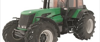
8-wheel tractor MTZ-3522
Another option to increase the tractor's maneuverability and reduce its pressure on the ground is to convert the equipment to an eight-wheel base. This modification is best carried out in a specialized center.
Installation of the GAZ-66 bridge at MTZ
Another tuning option aimed at improving the MTZ’s cross-country ability, as well as its traction characteristics, is the installation of a GAZ-66 axle
This type of alteration is extremely complex, so we strongly advise you to carefully study this issue on the Internet, and when working directly, pay attention to the following points:
Ways to increase the power of MTZ tractors
As obvious as it may seem, one of the main ways to, if not increase, then at least maintain the power of any tractor is to carry out timely maintenance and repairs - do not forget about this.
Reverse gear design
The reverse gearbox is a unit installed between the clutch and the gearbox. Performs the function of quickly changing the direction of movement back and forth without changing the gear ratio. Simply put, at the same speed you can move forward or backward, which allows you to use the “shuttle” mode.
The design of the reverse gearbox consists of two groups:
- Mechanical transmission unit.
- Reverse gear control.
The first group consists of a set of gears that transform (change direction) the power flow. The second group ensures timely activation or deactivation of a certain operating mode, allowing you to move forward or backward. In the MTZ-82 gear shift circuit, the action of the reverse gearbox is an important and responsible function that makes it possible to instantly change motion, which is often required in difficult field conditions.
Primary shaft
The gearbox of the MTZ-82 tractor has an aggregation with the primary power take-off shaft. It is installed horizontally and is connected at one end to the clutch basket (release plate), and at the other to the secondary shaft coupling. The primary shaft is supported by two bearings. It is equipped with longitudinal teeth on which gears of 3, 4 and 5 speeds are installed. In addition, the input shaft is connected to the creeper using a gear drive.
The design of the transmission does not allow for the input shaft to operate in the neutral position. The device operates only when the synchronous or independent drive is switched on.
Engine tuning and technical parameters
Each tractor has its own characteristics, and the engine must be looked at from different angles. Tuning MTZ-40 will be radically different from tuning MTZ-3022 or MTZ-892. Usually, alterations affect the insides of the power plant, that is, its basic properties are revised. The MTZ-50 diesel engine can receive a methane supplement. This makes it possible to reduce diesel fuel consumption and replace it with natural gas by 80%.
As an option, for tuning the MTZ-1221, in relation to the engine, technical inspections and repairs are considered if necessary and when the scheduled inspection is due. Some tractor drivers decided that a complete change in the power plant would suit them and opted for more powerful engines. In practice, one can trace the tendency that installing a power unit taken from other special equipment at MTZ is the most correct solution when you want to improve technical performance, and you can get by with minor alterations.
But such an upgrade can be expensive - the new engine will need to be properly registered and obtain a work permit. Sometimes the amount is so exorbitant that it is easier to use it to purchase a new, more powerful and modern tractor.
During the conversion of the MTZ-82 tractor to the MTZ, a special device is often installed, which makes it possible to significantly increase the power of the power plant. This function is performed by the turbine at MTZ. Sometimes it’s worth resorting to a trick and taking elements of other tractors (for example, the MTZ-80 cab) and tuning the MTZ-82 or any other Belarusian tractor.
Among the main technical parameters that are being improved is the tractor's cross-country ability. There are several ways to improve different models, including the MTZ-892 tuning operation:
- Installation of middle wheels, due to which the tractor begins to move not on 4 wheels, but on 8. This makes it possible to increase the area of interaction between the wheels and the soil, and the tractor becomes more stable.
- Half-track installation. Used for the same purpose as the previous method. It involves the installation of rubber-metal tracks that work simultaneously with tension devices. The tractor begins to exert less pressure on the soil and can work in marshy areas.
Important TOP 3 popular Volvo brand forklifts
Sometimes remaking the MTZ-80 involves replacing the axle, which is taken from the GAZ-66. But the procedure is very difficult to carry out on your own; it is recommended to seek help from specialists in the field of repair of agricultural machinery so that the modification is carried out professionally.
Maintenance of the MTZ-82 gearbox
The design of the MTZ-82 gearbox has many moving and rubbing parts. Trouble-free operation of all elements is possible only if they are in proper condition, timely technical inspection, and abundant lubrication of all parts. The following malfunctions may occur from irregular maintenance:
- Creaking noise when changing gears.
- Increased lining clearances.
- There is play in the gear shift lever, leading to incomplete or involuntary gear engagement.
- Extraneous noise, grinding or creaking in the box during operation, indicating a violation of the interaction of the elements.
A technical inspection of the gearbox should be carried out once a month. This allows you to increase the service life of the gearbox and rear axle, and ensure appropriate operating conditions for all structural elements. Regular inspection will allow you to promptly detect signs of emerging faults and take measures to eliminate them, without leading to premature major repairs.
Video on the topic: Test drive and review of the Belarus MTZ-82 tractor
MTZ 82 gear shift diagram
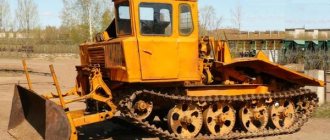
MTZ-80/82 “Belarus” is one of the most popular tractors in the former USSR. This machine has been produced in Minsk, as well as at a number of other factories in the USSR since 1974 and continues to be produced to this day.
Initially, the tractor was developed as a light agricultural machine. However, in our country it has received much wider application. On the basis of MTZ-80/82, a variety of construction equipment was made, such as bulldozers and excavators, which became no less famous than agricultural equipment.
Therefore, information about the operation and maintenance of this tractor will be of interest to the widest public. The article below will discuss in detail the MTZ 82 gearbox, its capabilities, as well as the procedure for switching MTZ 82 speeds.
Installing a dispenser on an old-style MTZ 82
The main difficulties when installing the dispenser on tractors of the earliest production MTZ 82 (80) is fastening the bracket for the hydraulic cylinder to the bridge beam in the absence of installation space. The network shows the experience of practitioners from several options for solving this problem using clamps on the beam or direct welding of the bracket.
Bracket on the bridge beam
The most acceptable solution that ensures a reliable connection is the following technology, which is feasible under normal plumbing conditions:
MTZ-82: gear shift diagram, mode switching order
The gear shift pattern of the MTZ-80/82 “Belarus” tractors is significantly different from that of cars, so it’s worth talking about it in more detail.
The MTZ 82 gearbox is designed for 11 speeds, including 12 neutral gears. Interestingly, all these speeds are activated with one lever.
You can find out which gear is which in the picture below:
Gear shift diagram on MTZ-80/82 “Belarus” tractors
In the diagram, Roman numerals indicate the modes:
The first thing you need to do is turn on the mode you plan to move. It turns on in the extreme left position. At the same time, please note that the position of the handle when turning on the mode differs from its position when turning on the speed. When the mode is turned on, the gearshift knob travel is much greater.
The mode is activated as follows. The clutch is depressed all the way (on a tractor it is located in the same place as on a car, it is the leftmost pedal), after which the mode you need is activated.
After the mode is turned on, return the handle to the neutral position and you can turn on the speed. When you turn on the downshift mode, you have access to speeds 1, 3, 5, 4, as well as a low reverse gear.
If you need to switch to the boost mode, then to do this you first need to turn it on by moving the knob to the left up. After that, you return it to the neutral position and increasing modes are available to you. That is, 2, 6, 8, 7 speeds and high reverse.
Tuning the cabin of MTZ 80, 82
All changes inside the tractor are carried out to improve comfort in the cab. In modifications of tractors produced quite a long time ago, there are no such convenient devices as a radio tape recorder, additional lighting, or a navigation system.
Additional devices are easy to find on sale. This significantly expands the possibilities of tuning the MTZ 80 cabin in terms of using diodes in the lighting, installing a comfortable seat, and tinting the windows.
Improving vehicle performance
One of the most popular areas of internal tuning of a tractor is improving the cross-country ability and traction parameters of the machine.
An interesting option is the installation of a GAZ-66 bridge. When carrying out such work, it should be taken into account that:
In any case, it is better to trust such work to specialists. Timely maintenance helps maintain the power of tractor equipment. It is possible to increase power by replacing the turbine or the entire engine with a more powerful one.
Often, when tuning MTZ, it pays to install the best units from other tractors of the brand.
But these works will have to be legalized by registering with the authorized bodies. Also keep in mind that the price of a “remodel” may be comparable to the cost of a new car.
Where to buy spare parts for tuning the MTZ cabin?
On our website you will find the most complete range of spare parts for vehicle modernization.
If you don’t know how to choose components, call the manager by phone. A specialist from our company will help you not only quickly select the necessary parts, but also organize delivery to any city in Russia.
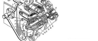
Gearbox design MTZ-80 and MTZ-82
The MTZ-80/82 gearbox is a cast-iron crankcase containing 4 shafts on which gears are mounted. The main shafts are the primary and secondary, which are located one above the other. When generating torque, they are helped by two other shafts - intermediate and additional.
All gearbox shafts rest on bearings located in the walls of the box housing, as well as in the central partition.
The gearbox housing itself is filled with transmission oil, which provides lubrication of the rubbing surfaces. To prevent oil from leaving the crankcase, there are seals at the ends of the shafts.
Photo of MTZ-80/82 gearbox
Initial installation of the ignition grouse of the D-240 engine
In order to initially install the ignition ripple on the D-240 engine. It is necessary to bring the piston of the 1st cylinder to TDC on the compression stroke. It can be done this way.
Take an electrode or a piece of wire and lower it into the hole under the nozzle until it reaches the piston. Using the valves on the head, it is necessary to catch the compression stroke and bring the piston to top dead center. When the electrode moves upward, turning the crankshaft with a wrench will catch the TDC. When we insert TDC we do the following.
Using a wrench, we turn the injection pump by the shaft on the pump, which secures the hazel grouse gear. We bring the MTZ-80 injection, observing the fuel inlet from the first plunger.
When we have the piston in the compression stroke and the pump in the injection stroke, then we install the ignition switch in place and secure it with 2 bolts. This will be the correct insertion of the ignition, and then, as the engine operates, at your discretion, set the ignition earlier or later by moving the 2 ignition adjustment bolts.
Primary shaft
The input shaft is one of the most important parts of the gearbox. It is through the clutch that the torque from the engine enters the gearbox. One side of the input shaft interacts with the clutch basket. The other side transmits torque to the secondary shaft coupling.
The primary shaft in the box rests on two bearings and has gears on it, which are responsible for turning on the 3rd, 4th, and 5th speeds of the tractor.
Another important function of the input shaft is to transmit rotation to the speed reducer. It is connected to it through a gear drive.
Operating procedure for the MTZ-80 and MTZ-82 gearboxes
The figure above shows a diagram of the MTZ-80/82 gearbox. It will be needed to understand how the checkpoint operates.
Torque from the engine, through the clutch, is transmitted to the input shaft, which is designated by the number 1. There are two gears on the shaft (numbers 3 and 4). These gears can move along the shaft; they are responsible for 5, 4, 7, 8 speeds. The order in which these speeds are turned on can also be seen in the figure.
In addition, gear 4, when engaged with gear 5, engages 9th gear.
The intermediate shaft, designated 14, is responsible for transmitting torque to the gearbox secondary shaft, designated 7.
The moving gears on this shaft are marked with the number 18. It is the block of these gears, when moving forward along the shaft, that is responsible for 1, 3, 4, 5, as well as 1 reverse speed. If this block moves backward, then it is responsible for engaging 2, 6, 7, 8 and 2 reverse gears.
The additional shaft, designated 27, is involved in generating the torque of 1st and 2nd forward gears, as well as both reverse speeds.
The secondary shaft (number 7) transmits torque directly to the drive wheels. All transmissions go through intermediate or additional shafts, and only in direct 9th speed 2 shafts are involved: primary (1) and secondary (7).
Operating principle of the ignition system
The ignition system is used for reliable and timely ignition of the combustible mixture entering the cylinder. It consists of a magneto, a spark plug and a high voltage wire.
The operating principle of this element is quite simple and reliable at the same time - when the working mixture enters the cylinder of the starting engine, it is ignited by means of an electric charge formed between two electrodes on the spark plug. For the highest quality charge, a fairly high voltage is required, approximately 10-15 kV, which is created in a special device - a magneto, which combines a number of functions - a breaker, an alternating current generator and a transformer.
The D-240 engines use a magneto with right rotation and a constant spark generation rate. The magneto drive comes from a rigid coupling half through the drive gear on the starting motor.
Design of the reverse gearbox MTZ-80 and MTZ-82
A reverse gearbox is located between the clutch housing and the gearbox. This unit is responsible for quickly changing the direction of movement from front to rear.
The reverse gearbox consists of two units: a block of shafts and gears, as well as a gearbox control unit. A drawing of the reverse gearbox can be seen in the figure below:
The numbers in the figure indicate:
- reverse gear cover;
- synchronizer;
- lever;
- roller with fork;
- retainer ball;
- cup;
- sleeve;
- gearbox input shaft;
- driven gear;
- Transmission;
- front socket;
- clutch housing;
- idler gear;
- satellite axis;
- pin;
- satellite;
- ball bearing;
- power shaft;
- drive gear;
- lid;
- parallelogram mechanism;
- reverse gear control lever.
Adjustment procedure
The need to install injection arises when replacing a high-pressure fuel pump (HPF) or installing it after repair, as well as after repairing the piston group of a diesel engine. The adjustment is carried out provided that the fuel equipment, injection pump and the adjusted gas distribution mechanism of the diesel engine are in good working order. The installation process consists of the sequential operations described below.
Installing the first cylinder on the compression stroke
On the right side, in the direction of travel of the machine, in the wall of the engine mounting to the clutch housing, above the longitudinal beam of the tractor frame near the oil filler neck, there is an installation dipstick. With its short threaded part it is screwed into the mounting wall and with its long threadless part it is installed outside. If it is necessary to install the first cylinder in the “compression” stroke position, the dipstick is installed in the hole, resting its long part against the engine flywheel. Slowly turning the diesel crankshaft, find a position in which the probe will fall into the hole on the flywheel and enter the body of the part completely by 4-5 cm. It is important not to confuse the installation hole with the technological, balancing drillings of the flywheel, which are much smaller in depth. The found position corresponds to an advance of 26 ̊ before the piston of the first or fourth cylinder approaches TDC. This position corresponds to the technical requirements of D 240 for setting the start of fuel injection into the cylinder during the “compression” stroke. To determine which of the cylinders in the first or fourth the “compression” stroke has begun, you need to remove the valve cover. A pair of closed valves will indicate in which of the two cylinders (first or fourth) the “compression” stroke has begun.