Dismantling and disassembling the rear axle MTZ 80.82
After installing the rear part of the equipment on the repair stand, proceed to disassembly. Remove the cab, rear wheels, fuel tanks and brackets. Go to the transmission. Dismantle the components of the pneumatic system, fuel pipelines: taps, adapter and brackets. On the power regulator there are five oil pipes, rods (positional, power), and a control roller. Unfasten the nuts and remove the parts. Throw the rods back.
Subsequent stages of dismantling:
- Proceed to remove the power cylinder and regulator.
- Disconnect the studs and remove the PTO control lever. Remove the hydraulic accumulator, ABD oil supply pipes, brake rods, and brakes.
- Remove fasteners, rear axle axle sleeves, and covers. Remove the differential cups and bearing cups.
Place the differential on the mounting table. Remove bolt connections, washers, cover. Disassemble the assembly by removing the crosspiece, gears, and satellites. Remove bearings and seals. Evaluate the technical parameters of spare parts. The presence of defects, sharp edges, burrs, and nicks is unacceptable. If problems are found, replace worn elements with new ones.
Rear axle of the MTZ 82 tractor: differential, main and final drives
The rear axle of the MTZ 82 tractor is used to transmit torque from the longitudinally located secondary shaft of the gearbox through the main gear and differential to the final drives and axle shafts on which the rear wheel hubs are mounted.
The entire rear axle device is housed in a cast-iron housing, to the rear wall of which is attached a rear power take-off shaft gearbox, a towing device and a rear linkage mechanism mount, and a gearbox is attached to the front wall. In the side walls of the housing, the cups for the final drive gears, rear axle shaft sleeves and brake casings are inserted into the bores and attached to the walls using bolts. The top of the rear axle housing is closed with a cover made of steel sheet.
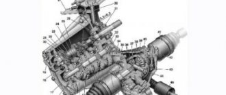
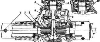
Diagram of the rear axle of the MTZ 82 tractor: 1 and 12 - final drive gears; 2 — satellite washer; 3 — differential crosspiece; 4 — satellite; 5 — differential housing; 6 — driven gear of the main gear; 7 — driven gear nut; 8 — locking plate; 9 — differential housing cover; 10 - tapered bearing; 11 - bolt; 12 — final drive driven gear; 14, 26 and 36 - bearings; 15 — hatch cover; 16 — rear axle housing, 17 — axle shaft sleeve; 18 — connecting disk; 19 — intermediate disk; 20 - spring; 21 — squeezing disk; 22 — pressure disk; 23 — axle shaft; 24 and 32 - cuffs; 25 - cover; 27— locking mechanism cover; 28 — diaphragm cover; 29 — diaphragm; 30 — adapter; 31 — locking shaft; 33 — casing; 34 — blocking clutch housing; 35 — glass lid; 37 — cup of bearings; 38 — shims; 39 — support washer; 40 — semi-axial gear; 41 — main gear drive gear; 42 — secondary shaft of the gearbox; 43 — rear axle cover.
main gear
It is a pair of bevel gears equipped with a spiral tooth. The gear ratio of this pair is 3.42 (41:12). The drive gear is cantilever mounted on the splines of the secondary shaft of the gearbox and is fixed with a nut screwed onto the thread of the shaft shank. The driven gear is attached to the differential housing flange using nuts and bolts, locked in pairs with folding plates.
Differential MTZ 82
The differential device is a planetary mechanism used to distribute the supplied torque between the axle shafts and create the possibility of rotation of the drive wheels at different frequencies when turning the tractor and on uneven surfaces.
When turning, the wheels move in arcs of different lengths. If the wheels were installed on a solid axle, then they would slip relative to the ground and the common axle would twist. As a result, the drive wheels are installed on different axle shafts, which are connected by a differential.
Differential device
The differential consists of a spider, a housing, a cover, side gears and satellites. The crosspiece is installed between the cover and the body. The holes for the fit bolts, with the help of which the cover and the housing are tightened, and the crosspieces are made during the joint processing of the differential housing and cover assembled into one. For this reason, both parts are marked with the same number. It is not allowed to disassemble the cover and housing, and during assembly of the differential it is necessary to match these numbers on the mating parts. There are four satellites with support washers installed on the crosspiece. The satellites are constantly in mesh with two semi-axial gears, whose hubs are inserted into the bores of the differential cover and housing, and their internal splines are connected to the shafts of the final drives and drive gears.
The assembled differential rotates on two tapered roller bearings, mounted with outer races in the bores of the cups, and with inner races mounted on the cover and housing.
Automatic differential lock MTZ 82 (ABD)
While making it easy to turn the tractor, the differential can at the same time worsen its traction properties. For example, if the traction of one wheel on a slippery surface is insufficient, the second wheel, despite the fact that it has more reliable traction, will not be able to use it and create more traction force than a wheel on slippery soil. To eliminate this drawback, an automatic differential locking mechanism is used, which provides the wheels with different traction forces.
The design of the differential locking mechanism is made in the form of a friction clutch located on the shaft of the left drive gear of the final drive, as well as a control mechanism, the device of which includes a sensor with a pressure reducing valve and a control valve located in the power steering. The booster hydraulics are connected to the locking clutch using oil lines. The three-position tap of the blocking sensor is controlled directly from the tractor cabin.
The driven and driving disks of the locking clutch are respectively connected to the grooves of the locking clutch housing and to the splines of the outer end of the left drive gear. The locking shaft is rigidly connected to the coupling body. This shaft passes through the inner hole of the drive gear and its splined end is connected to the differential spider. When oil enters under pressure from the power steering into the cavity between the diaphragm and the cover, the force is transmitted through the pressure plate to the clutch discs. Due to frictional forces, the compressed disks unite the left drive gear, the left differential side gear connected by splines, the crosspiece and the locking shaft. As a result, the differential locks, creating a solid axle, since the satellites are not able to rotate relative to the semi-axial gears.
The differential lock controls located in the cabin and the sensor valve located on the power steering have three positions: the first position - the lock is off, the second - the lock is on, the third position - the forced differential lock is on.
If the differential lock is turned off, then oil is not supplied to the diaphragm, the clutch discs are released and the unlocked differential functions as a normal one. When the lock is turned on, the automatic differential lock is activated, depending on the position of the front steering wheels.
Differential locking is recommended for use during field work; it is especially effective when working on slopes and plowing. When performing these works, differential locking not only reduces wheel slipping, but also promotes straight-line movement of the tractor. On high-quality road surfaces, it is recommended to disable the locking to avoid tire wear. On slippery road surfaces, you can work with the lock engaged, but at a speed not exceeding 10 km/h. Forced blocking is used briefly to overcome various obstacles.
Final drive MTZ 82
Final drives are the last stage of the transmission that transfers torque and rotation from the differential and final drive to the tractor's drive wheels. All final drives are single-stage gearboxes equipped with a pair of spur gears with a ratio of 5.308 (69:13).
The drive gears are made as a single unit with a shaft, the ends of which have splines. One end of the shaft is connected to the differential side gear, and the other to the brake connecting discs. The left drive gear is connected by an external spline shank, in addition, to the differential lock clutch discs. The connecting discs of the locking clutch and brakes are unified. Each of the drive gears rotates on two roller bearings, the inner races of which are mounted on the shaft, and the outer races are mounted in the bores of the cups.
Unlike the right one, the left drive gear is elongated and has a through hole through which the differential lock shaft passes.
The driven gears are mounted on the splines of the rear wheel axle shafts. Each axle shaft rotates on two identical ball bearings, one of which is mounted in the bore of the bridge body bulkhead, and the other in the bore of the axle shaft sleeve. The axial movements of the axle shaft and bearings are limited by the cover and the retaining ring. The axle shafts are sealed with a self-clamping cuff mounted in the cover.
The protruding outer part of the axle shaft has a groove into which a key is inserted, with the help of which torque is transmitted from the axle shaft to the split wheel hub.
Assembly and installation of the rear axle MTZ 80.82
The driven gear and transmission components are assembled in the reverse order. The installation of cuffs in the bearing cup covers requires attention. Seals are installed in a certain direction. The working edges must face the bearings.
The crown of the bevel gear must be stationary, the bearings are pressed until they stop. The nuts must be secured with locking devices, the bolts must be tightened and secured in pairs with wire. After assembly, the satellites and gears should rotate freely. Jams are not allowed.
Subsequent assembly:
- Install the axle sleeve. Follow the reverse sequence of disassembly. Use grease to treat the bearings when installing the cover. Check the rotation of the nodes. It should be smooth, without interference.
- Install the drive gears and differential. Check clearances and fastenings. Install the gaskets and fill with oil. Reassemble all dismantled components.
- The lateral clearance in the secondary shaft gear should not exceed 0.2-0.55 mm. Check the parts by turning the gear at 3 points. Make adjustments. To do this, move the gaskets from under the flange of the right glass and vice versa. Do not change the total number of gaskets.
Before installation, it is recommended to flush the fuel tanks, oil and fuel pipelines. The seats must be treated with lubricant.
Locksmith assistant
If there is increased noise and knocking in the rear axle housing, lubricant leakage through the seals, runout of the rear wheels on the axle shafts due to destruction of the bearings, open the rear axle, remove the differential assembly, final drives, and eliminate the malfunction by replacing unsuitable parts.
REMOVAL AND DISASSEMBLY. Place the rear of the tractor on stands. Remove the rear wheels. Remove the cabin. Disconnect and remove from the transmission the pneumatic system assemblies with pipelines: brake valve, brake valve bracket, disconnect valve, pneumatic adapter. Remove the fuel tanks and their brackets. Unscrew the nuts and remove the five oil lines from the power regulator.
Rice. 1. Power regulator. 1 - power regulator;
2 - screwdriver; 3 — power regulator control roller; 4 - cylinder oil lines. Unpin and disconnect the power and position rods from the power regulator and fold them back along the tractor. Unfasten the roller 3 (Fig. 1) for controlling the power regulator.
Disconnect the hose fittings from the power cylinder. Disconnect the cylinder from the bracket and tilt it back along the tractor. Unfasten and remove the power regulator assembly with bracket and the regulator control sector assembly from the transmission. Unpin and remove the PTO control lever from the rear right cab bracket. Remove the accumulator. Unlock, disconnect and remove the PTO shift lever. Disconnect the automatic differential lock (ADL) oil line. Unlock and unscrew the brake rods of the adjusting forks. Disconnect and remove the ABD assembly, remove the left and right brakes. Unfasten and remove the rear axle cover. Disconnect and remove the axle sleeves. Disassemble the axle sleeves one by one. Press the axle shaft out of the sleeve (Fig. 2). Fig.2 Pressing out the ball bearing with the axle shaft from the final drive axle shaft sleeve. 1 - press;
2 - axle shaft; 3 — axle sleeve; 4 — stand Remove the covers of the differential cups, disconnect and press out the bearing cups assembled with the drive gears, using dismantling bolts, as shown in Fig.
3. Fig. 3 Removing the bearing cup assembly with the drive gear. 1 - glass;
2 - bolt; 3 — wrench Remove the differential assembly from the housing and install it on the mounting table stand (Fig. 4).
Rice. 4. Differential prepared for disassembly. a — differential assembly on the device;
b - device; 1 — differential; 2 - device; 3 - workbench; 4 - mandrel; 5 - base. Disassemble the differential by unlocking and unscrewing bolts 2 (Fig. 5), remove cover 7, support washer 4, side gear 5, spider assembly 8, another side gear 5 and support washer 4, remove support washers 3 and satellites 6 from crosses. Press the drive gears out of the cups and remove the bearings from them. Remove the sealing collars from the glasses. Check the technical condition of the differential and final drive parts in accordance with the data in the table. Burrs, nicks, sharp edges and other defects are not allowed on the working surfaces of side gears, satellites, crosspieces and support washers. Replace parts if necessary (the differential housing and cover cannot be disassembled). differential and final drive driven gear (see Fig. 5) in the reverse order of disassembly.
Rice. 5. Differential assembly. 1 - safety wire;
2 - bolts; 3 — satellite support washer; 4 — support washer of the semi-axial gear; 5 — semi-axial gear; 6 — satellite; 7 - cover; 8 — crosspiece Pay attention to the installation of the cuffs in the bearing cup covers (Fig. 6), check the immobility of the bevel gear ring on the housing;
the nuts must be secured with folding plates. The semi-axial gears and satellites should rotate freely on the axes of the cross by hand, without jamming. Rice. 6. Cup lid assembly. 1 - cover;
2 - sealing collar; 3 — sealing ring The bearings must be pressed in until they stop. The bolts securing the differential cover to the body must be tightened to a torque of 7.5–8 kgf m and in pairs, and the tension of the wire must coincide with the direction in which the bolts are screwed in; the ends of the wire must be tightly twisted and cut at a distance of 5–6 mm from the point of their connection. Before pressing the outer rings of tapered bearings into the differential cups, thrust rings must be installed, the chamfer on the edge of the ring hole must face towards the bearing. The sealing collars must be installed in the cup covers with their working edges towards the bearings. The axial clearance in the bearings is 0.01–0.05 mm. Gaskets must be installed so that the parting line is vertical. Assemble the axle shaft sleeves in the reverse order of disassembly. In this case, the edge of the spring of the sealing cuff must be directed towards the bearings, the cuff must be pressed in until it stops; When installing the sleeve cover, place 40–50 g of solid oil (US-1 or US2) into the bearing. Install the differential assembly and the final drive gears assembled with the cups into the rear axle in the reverse order of disassembly. Check and adjust the side play in the secondary shaft gear mesh. It should be in the range of 0.2–0.55 mm. The clearance is checked by turning the gears at three points. Fluctuation of the gap at these points is allowed no more than 0.25 mm. The adjustment is carried out by moving part of the adjusting shims from under the flange of the left glass under the flange of the right one or vice versa, without changing the total number of shims. When checking “for paint”, the teeth must adhere to at least 50% of the surface with the print located in the middle part of the tooth or closer to the top of the cone. Install the axle sleeves into the rear axle until they stop, lubricating the bearing seats with grease. Check the rotation of the axle shafts in the bearings (it should be free, without jamming). Install the gasket on the rear axle, having previously lubricated it on both sides with grease, and the cover assembly. Fill the rear axle housing with transmission oil. Install all previously removed components and parts on the tractor in the reverse order of disassembly. Before installation, wash the removed fuel and oil lines and fuel tanks.