- home
- Media center
- Articles
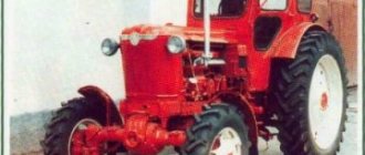
- Hypoid bridge ZIL-130
Menu
- News
- Articles
- Video materials
- Photo materials
- Publication in the media
- 3D tour
24.02.2021
The ZIL-130 hypoid axle is also often called the rear drive axle. It performs a set of the following functions:
- transmission of torque in the direction from the cardan-type transmission to the rear wheels of the vehicle;
- process of inhibition;
- the role of a load-bearing structural element, which is responsible for transferring the load from the car body to the rear wheels and hubs through the spring suspension.
Maintenance and operation
As has already been seen based on information on design features, the ZIL-130 hypoid bridge has significant differences from a simple bridge. For this reason, the care, maintenance and operation of the element require a slightly different approach. Let's take a closer look.
Main aspects:
- Regular inspection and checking the level of wear of brake drums and linings must be carried out. As soon as the distance from the first surface of the lining to the subsequent rivet decreases, and the gap is less than 0.5 mm, replacement of the linings is required.
- Wear of the brake linings on the ZIL-130 hypoid axle indicates the need to connect the shoes to the drums using special adjusting levers. It is important that the rod free play of the chambers responsible for braking should not exceed 40 mm.
- If we are talking about a disinhibited process, then the rotation of the drums should occur in a free mode. That is, the presence of play in the wheel bearings is unacceptable in this case.
- In addition, it is important to ensure that there is no oil fluid inside each of the brake mechanisms.
- The dimensions of new drums are usually 4.2 cm, so exceeding 4.26 is also considered unacceptable and requires intervention.
- The condition of the gearbox also needs to be checked for the presence or absence of play in the fastening system. Therefore, in some cases it is necessary to additionally tighten the fastening nut. At the same time, the bearings are checked.
- Thermal clearance is required inside the gear meshing.
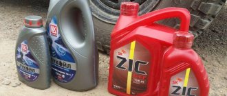
The hypoid axle of the ZIL-130 truck is included in the list of parts that require routine maintenance work. To do this, it is necessary to regularly replace the oil fluid in the bridge housing. There is a special lubrication map for this. The use of only proven and high-quality transmission oils is encouraged. The main quality indicators are the kinematic viscosity at high temperatures for each of the components of the hypoid bridge. In addition, the oil must have sufficient fluidity during low ambient temperatures.
It is important that replacing the oil fluid for the ZIL-130 hypoid bridge can only be done when the main element is preheated. This is how the oil drains and the filler hole opens.
With proper and timely maintenance, the hypoid axle on the ZIL-130 car is considered a reliable element that can operate for a long period of time. If all rules are followed, expensive repairs will not be required.
Information for individuals
In what ways can I pay for the ordered goods?
- Cashless payments.
- If it is not possible to transfer funds from the current account, our organization issues an invoice to the individual, which he can pay at any bank.
When can I make payment?
- Full payment upon purchase. NOTE! In this case, the order is sent by any transport company.
- Partial prepayment. Part of the cost of the goods is paid, the rest of the amount is paid after the unit arrives at the terminal of the transport company in your city. NOTE! In this case, the order is sent exclusively by Business Lines.
IMPORTANT! In case of full or partial payment, we will send you by mail a copy of the issued delivery note, certified by a seal, indicating the name of the product and its cost. The original invoice will come with the goods.
Product characteristics:
| Catalog number: | 130-1700010/130-170009 |
| car brand | ZIL |
| Car model | ZIL-130, ZIL-131, ZIL-5301 (Bull) |
| Type of equipment | Cargo |
| Country of Origin | Russia (RF) |
| Manufacturer of spare parts | Autohis |
| Number of gearbox stages | 5 mortar |
| Installed with motors | ZIL 130-131 |
| Drive unit | Rear (FR) / Full (4WD) 4x4 |
| Weight: | 90 kg. |
| Guarantee: | 6 months |
Short description:
How to order a spare part
Leave a request using the feedback form, or call the toll-free number
Get advice from a specialist and discuss the details of your order
Select the delivery method that suits you (by phone)
Choose a convenient payment method and confirm the order (by phone)
- Delivery
- Payment
- Guarantee
- How to order
WE WILL CHOOSE the optimal delivery method, taking into account the delivery time and cost acceptable to you
WE WILL SEND the necessary spare part to your city using your preferred transport company or we will independently select one that will meet your expectations in terms of time and cost. The list of companies we cooperate with can be found below.
WE WILL DELIVER the spare part, regardless of its weight and cost, FREE OF CHARGE, to the terminal of the transport company you choose. Thus, you pay for delivery services exclusively to the transport company
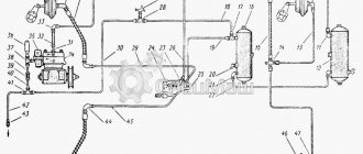
REMOVAL AND DISASSEMBLY OF THE REAR AXLE
To disconnect the rear axle, the vehicle must be placed on a flat horizontal platform or on an inspection ditch equipped with a lifting device. Using a lifting mechanism, lift the rear of the car so that the rear springs are freed from the load. Disconnect the ends of the rear suspension springs from the frame brackets and lift the frame, first placing supports or a special jack under the axle gearbox (Fig. 5-3). Disconnect the propeller shaft from the rear axle drive gear flange. Disconnect the brake hoses. Roll the rear axle out from under the frame, supporting it by the gearbox. Lower the frame onto the stands.
Dismantling the rear axle with two-stage final drive
Remove wheels, springs and brake chambers. Drain the oil, remove dirt, wash the bridge with a degreasing solution and blow off with compressed air.
Disassembly of the rear axle should be done on a special stand model 689-00 (Fig. 5-4). If there is no stand, disassembly can be done by installing the bridge on stands. 1 To remove axle shafts and wheel hubs, unscrew the nuts securing the axle shaft to the hub and remove the spring washers. Screw two M12x1‚75 bolts into the holes of the flange (Fig. 5-5), move it from place, and then manually remove the axle shaft flange gaskets. Using the same method, remove the other axle shaft from the rear axle housing. In Fig. Figure 5-6 shows the removal of the rear wheel hubs using a puller. And to do this, you need to turn the power screw 2 to its original position, install the flange of the ring grip 1 on the wheel studs and secure it with wheel nuts.
Disconnecting the rear axle from the frame
Then install the power screw stop at the end of the axle housing and rotate the power screw with handle 3 of power screw 2 clockwise until the wheel hub is completely removed.
To remove the main gear, you need to turn the rear axle so that the main gear is positioned vertically upward. Unscrew the bolts and nuts of the studs securing the gearbox housing to the rear axle housing.
Install a bracket on the flange of the main gear reducer (Fig. 5-7) and use a lift to remove the main gear from the rear axle housing. Disassembly of the main gear and differential is carried out on a stand or bench in the following order.
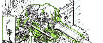
Disassembling the ZIL gearbox
To remove and disassemble the drive bevel gear assembly, unscrew bolts 23 (Fig. 5-8) and, lightly tapping the bearing cup with a hammer, remove it together with the drive
with gear 24. Remove adjusting shims 11.
To disassemble and install the cup 4 (Fig. 5-9) of the bearings assembled with the drive bevel gear in fixture 2 and secure it with clamps 3 and clamp 1, which will keep the gear from rotating.
Unscrew and unscrew nut 17 (see Fig. 5-8) securing the flange, remove the nut support washer and flange 18, tapping it with a hammer. Unscrew the bolts 15 securing the cover 19, remove the cover with the gasket and the thrust washer 20. If the cuff 16 is faulty, press it out of the cover.
To press out the drive bevel gear shaft, install the bearing cup with the shaft on the press pads and press out the shaft (Fig. 5-10). If there is no press, the same operation can be performed by striking the end of the drive gear shaft against a wooden spacer.
Removing the gearbox from the crankcase
Remove the drive bevel gear 24 from the crankcase (see Fig. 5-8) together with the inner ring of the bearing 12, adjusting washers 22 and spacer sleeve 13. Remove the front bearing from the glass, press the outer ring of the front bearing out of the crankcase using a mandrel model 80423.00 ( Fig.5-11). In the same way, but using a different mandrel, press out the outer ring of the rear bearing.
It is recommended to remove the rear bearing from the drive gear shaft using a puller 20P-7984 (Fig. 5-12) or a puller model I 80330.000.
gearbox ZIL-130
To remove and disassemble the differential, you need to bend the locking plates from the heads of bolts 2 (see Fig. 5-8) and unscrew the bolts securing the stopper 3 on both sides, remove the locking plates and stoppers of the adjusting nuts.
Devices
Unscrew the bolts securing the covers 29 of the differential cup bearings, unscrew these nuts with an angled socket wrench, mark the covers and remove them, mark and remove both adjusting nuts 4, remove the differential along with the bearings.
To disassemble, place the differential in a vice, holding it by the rim of the driven spur gear. Unscrew the nuts of the bolts securing the differential cups and the driven spur gear. Mark with a core the relative position of the differential cups (processing of the sockets for the differential crosspiece in the satellite cups is done as an assembly, and during disassembly it is necessary to keep the cups together without depersonalizing them).
Bearing removal
Remove the right cup and the right axle gear 32 with the support washer 31, remove the cross with the satellites and the satellite support washers, and then remove the left axle gear with the support washer,
Remove the driven spur gear from the left differential cup 5 using a copper mandrel and a hammer.
In this case, the puller I 80331.00. is installed so that the grips 5 pullers fit into the end of the inner ring of the bearing. To remove and disassemble the drive cylindrical gear, you need to unscrew the bolts 26 securing the bearing covers 9 and 27 with a spanner wrench and remove them together with shims 10 and the outer rings of the bearings.
A pack of shims on one side should not be mixed with a pack of shims on the other side; it is recommended that they be secured to their covers using thin wire. Remove the drive cylindrical gear 8 from the gearbox housing. To remove the right and left bearings, it is recommended to use a TsKB-2502 puller. The method of pressing the bearings is shown in Fig. 5-14
Pullers
Methods for pressing out the outer rings of bearings using a puller model 2480 are shown in Fig. 5-15. In Fig. 8-16 shows a puller model I 803.33.000.
If there are cracks or holes }: in the gearbox housing and bearing caps, damaged parts should be replaced. Welding of non-through cracks is allowed. Damage to the thread is allowed no more than two threads.
The permissible runout of the axle shaft, measured at a distance of 80 mm from the flange, is allowed no more than 1.0 mm.
The permissible runout of the axle shaft flange should not exceed 0.2 mm.
If there are breaks, signs of twisting, bending or cracks on the axle shafts, they should be replaced.
WATCH THE VIDEO
Information for legal entities
The goods are paid for by bank transfer.
How to get an invoice?
You send us your company details by email, we issue an invoice and draw up an agreement. The contract is signed by both parties and after that the client pays the invoice.
How to pay the bill?
Payment by bank transfer to the company's bank account using the details specified in the invoice. All accounting documents are sent along with the goods. Deferred payment is possible (by agreement with management).
All products in our online store have an extended warranty of 6 months (electronics have an extended warranty of 3 months). The warranty card is sent to the buyer along with the spare part.
What it includes:
Guaranteed replacement of spare parts in case of defects within 6 months
If a manufacturing defect is detected, you can exchange the part under warranty within six months after purchase.
For this:
- You must send the part back to us.
- Immediately after receiving the auto parts, we carry out defect detection of the goods (3-10 days).
- If the defect confirms a manufacturing defect, we will send you a new spare part. Our company will cover the shipping costs for sending the replacement part to you.
- If the defect shows that the spare part was damaged as a result of improper use, we can repair it with your consent at your expense. If we refuse to repair, we will send the part back to you. In this case, the transportation costs for sending the part are borne by you.
Repair parts
If a malfunction is detected, you can have the part repaired in our company.
For this:
- Send the part back to us.
- Immediately after receiving the auto parts, we carry out defect detection of the goods (3-10 days).
- After a defect, we can repair the spare part according to our price list with your consent. If we refuse to repair, we will send the part back to you. In this case, the transportation costs for sending the part are borne by you.
Our online store service allows you to place an order very quickly and easily!