Unscrew screws 6 (Fig. 37) and drain the oil. Ramp out the driven coupling half 1 in two places, ensuring the safety of the supporting sealing end of the driven coupling half. Place the coupling on the stand 6 (Fig. 38) and use a special key 3 to unscrew the housing 5 (see Fig. 37). Remove the drive half coupling 7, springs 12, shims 11, spacers 10 and weights 2. Considering that the coupling weights when installed in the unit are selected according to the static moment, it is necessary to maintain a paired set of parts. Press out cuffs 8 and 9, using mandrels, from the coupling body 5 and the drive coupling half 7.
After disassembly, check the technical condition of the injection timing clutch parts.
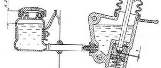
Rice. 37. Injection advance clutch:
1 – driven coupling half; 2 – coupling weight; 3 – load axis; 4 – sealing ring; 5 – body; 6 – screw; 7 – driving coupling half; 8, 9 – cuffs; 13 – spacer; 11 – adjusting shims; 12 – spring
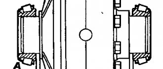
Rice. 38. Disassembly and assembly of the injection advance clutch:
1 – handle; 2 – installation pin; 3 – key; 4 – key rod; 5 – pin; 6 – stand; 7 – injection advance clutch
Clutch body
The housing must be checked for leaks; to do this, plug one of the oil drain holes, supply compressed air to the second at a pressure of 0.02-0.03 MPa (0.2-0.3 kgf/cm2) and immerse the coupling in a bath of diesel fuel . Air passage through the connections is not allowed.
Driven coupling half
A coupling half that has a worn keyway must be replaced with a new one.
Check the radial movement between the protrusions of the drive coupling half in the slots of the drive connecting washer, which should not be more than 0.3 mm, and the gap in the connection of the coupling load with its axis - 0.24 mm.
Coupling assembly
Install on axle 3 (see Fig. 37) of the driven coupling half weights 2 of the same size group (the number of the static moment group is indicated in Roman numerals on the polished surface of its side of the weight profile), which should rotate freely, without jamming, on their axes. Press the cuff 8 into the hole of the drive half of the coupling 7, install the drive half of the coupling on the driven hub using a mandrel that protects the cuff from damage. Insert the spring 12 weights, and the preload value of the springs in the assembled coupling should be 0.2-0.4 mm; It is permissible to install spacers 11 under the ends of the springs with a total thickness of 0.5-0.8 mm (in the assembled coupling, with the weights brought to the stop, the gap between the spacer and the profile of one of the weights should be no more than 0.1 mm). Press cuff 9 into clutch housing 5 flush with the inner end surface. Install rubber o-ring 4 into the groove of the driven coupling half and screw the coupling body 5 onto the driven coupling half 1. Fill diesel oil through the hole in housing 5 until it appears in the other hole. Install the assembled coupling onto the injection pump cam shaft and tighten nut 17 (see Fig. 29) securing the coupling to a torque of 98-117 Nm (10-12 kgfm). Check the characteristics of the automatic clutch; If it provides the required characteristics, remove it from the cam shaft of the pump and, after additional tightening of the housing on the driven coupling half, caulk it in two places to lock the thread.
Adjusting the high pressure fuel pump and requirements for adjustment equipment
The power and economic performance of the engine, as well as the reliability of its operation, largely depend on the care and quality of adjustment of the parameters of the fuel pump. Therefore, adjustment of the fuel pump must be performed by qualified personnel and using special equipment. It is recommended to regulate fuel pumps on stands NC-101, NC-108, manufactured by the national enterprise "Motorpal" (Czechoslovakia), MD 12 - by the enterprise "Mirkos" (Hungary), A1027 - Austrian and others, similar in design.
The pump is adjusted with a set of tested nozzles attached to the sections. They are installed on the engine in the order in which they are attached to the pump sections. In this case, the start of fuel supply by the pump sections, its magnitude and uniformity are regulated.
The start of fuel supply is regulated without an automatic clutch, injection advance at the beginning of its movement in the momentoscope (Fig. 39) and is determined by the angle of rotation of the pump camshaft when rotating it clockwise (as viewed from the drive side). The first section of a properly adjusted pump begins to supply fuel 37-38 degrees before the axis of symmetry of the cam profile. To determine it, it is necessary to record on the dial the moment the fuel begins to move in a momentoscope when turning the cam shaft clockwise. Then you need to turn it clockwise 90 degrees and record on the dial the moment the fuel begins to move in the momentoscope when turning the shaft counterclockwise. The middle between the two fixed points will be the axis of symmetry of the cam profile.
YaMZ-238 body parts
Housing spare parts serve as the frame of the YaMZ-238 engine and together provide structural rigidity. The YaMZ-238 cylinder block is the basic part of the eight-cylinder engine, cast together with the upper part of the crankcase from gray low-alloy cast iron, has five vertical transverse force walls in the area of the crankshaft main supports and closed water jacket belts around each of the eight holes for the cylinder liner. Each transverse wall has three supports: the lower ones for installing the crankshaft, the middle ones for the camshaft, the upper ones for the pusher axis. The block is bored together with the main support covers, so they are not interchangeable, they are installed in a certain position and secured with two long and two short bolts. The operating order of the cylinders is 1-5-4-2-6-3-7-8, the numbering of the cylinders from the fan. The direction of rotation of the crankshaft from the flywheel side is counterclockwise. The cylinders are arranged in two rows, at an angle of 90° to each other, with four cylinders in each row. The right bank of cylinders protrudes 35 mm relative to the left, due to the fact that two connecting rods are attached to one crankpin (one for the right bank, the second for the left). In the upper part of the cylinder block there is a bore for the camshaft, and above the camshaft tunnel there are inclined shafts for the pusher rods. Eight YaMZ-238 cylinder liners are wet type, made of fluoride cast iron, sealed by a cylinder head gasket in the upper part and rubber rings in the lower seating belt. The liners are flush with the mating plane of the block and are pressed by the YaMZ-238 cylinder head. The YaMZ-238 block head is one for a row of four cylinders, with a complex cooling cavity (combined with the block by bolted connections; during operation it may be necessary to control and tighten the bolts attached to the cylinder block) and an intake air manifold, has 2 valves per cylinder. The cylinder head contains guide bushings, seats, traverses, valve struts and rocker arms, and valves with springs. The gears of the crankshaft, camshaft, oil pump with intermediate gear, fan drive and injection pump drive are located in the front part of the cylinder block, in the space for placing the unit drives - between the block and the front (frontal) cover. The front cover of the YaMZ-238 cylinder block also creates a seal to the crankshaft toe (through the cuff). The YaMZ-238 flywheel housing made of gray cast iron closes the rear plane of the cylinder block and separates it from the flywheel, and has a bore for the starter flange.
| 238-1002012-D Cylinder block |
| 238N-1002012-I Cylinder block |
| 238B-1004005 Piston sleeve (YaMZ) |
| 238B-1004005-B Piston sleeve (YaMZ) |
| 238NB-1004005-A4 set of sleeve-piston, piston stakes (YaMZ) |
| 238-1003009 Cylinder head kit with valves |
| 238-1003013-D4 Old style block head |
| 238-1003013-Zh New sample cylinder head |
| 238D-1003013-A New sample cylinder head |
| 236-1002261-B2 Front cover assembly |
| 238-1002311-A3 Flywheel housing |
Installation diagram of fuel injection pump for YaMZ-238 engine
The fuel injection pump is installed according to the following algorithm:
- The driven coupling half (Fig. 1, 2) is installed on the advance coupling (damper coupling) and secured with bolts;
Rice. 1. Drive of the high pressure fuel pump of the YaMZ-238BE2 and YaMZ-238DE2 engines: 1 - drive coupling half; 2 — terminal connection bolt; 3 — flange of the coupling half; 4 — drive plates; 5 — bolts for fastening the drive plates; 6 — washers; 7 - damper coupling; 8 - pointer; 9 — high pressure fuel pump; A - mark on the damper coupling
Rice. 2. Drive of the high pressure fuel pump of the YaMZ-238BE and YaMZ-238DE engines: 1 - drive shaft; 2 — drive plates; 3 - driving coupling half; 4 - bolts; 5 — terminal connection bolt; 6 - bolts; 7 — driven coupling half; 8 — fuel injection advance clutch; 9 — high pressure fuel pump; A - mark on the coupling; B - mark on the index. - We turn the coupling so that the bosses of the driven coupling half are horizontal, and the notch on the end of the coupling is in the area of the pointer;
- Next, we will need the flange of the coupling half of the injection pump drive, assembled with the drive half-coupling and plate packs on the drive shaft, while the protrusion “A” on the flange of the coupling half will be located on the left, if you look at the drive from the fan side;
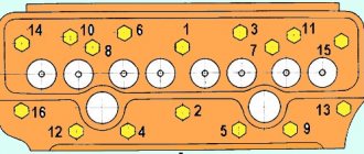
- Next, install the high-pressure fuel pump with damper coupling assembly on the engine and secure it with bolts. We adjust the plane of the plate packs by moving the coupling half flange along the drive shaft, and only after that we tighten the drive pinch bolt and set the injection advance angle. The fuel pump must be installed vertically on the engine cylinder block, and the mounting bolts must be tightened evenly, without blocking the pump. The last tightening torque of the pump mounting bolts is 30...40 Nm (3...4 kg/cm). We connect the pump sections with the injectors with high pressure fuel lines in the order shown in Fig. 3. Rice. 3. Connection diagram of high-pressure fuel lines between fuel injection pump sections and engine cylinder injectors.
- We adjust the fuel injection advance angle. We estimate the amount of oil in the housings of the high pressure fuel pump and regulator. If necessary, add oil to the level of the hole under the oil drain pipe. We connect the wire and oil drain tubes to the fuel lines.
Having started the engine, we adjust the minimum idle speed of the crankshaft in this way:
- Loosen the locknut and turn out the buffer spring housing by 2-3 mm.
- Using the minimum rotation speed limiting bolt (the control lever rests on this bolt), adjust the minimum idle speed until slight vibrations of the engine crankshaft speed appear. When the bolt is screwed in, the engine speed increases; when it is unscrewed, it decreases.
- Screw in the buffer spring housing until the rotation speed instability disappears. It is strictly forbidden to screw in the housing until its end coincides with the end of the locknut. Having completed the adjustment, it is necessary to secure the minimum speed bolt and the buffer spring housing with nuts.
The minimum idle speed is also adjusted in the new engine at the very beginning of its use. It is worth noting that it is strictly forbidden to violate the maximum speed adjustment made at the manufacturer without further control at the stand during operation.
Return to list of articles
| Buy spare parts for all-terrain vehicle MTLB with delivery throughout the Russian Federation |
| Buy spare parts for the GTT all-terrain vehicle with delivery throughout the Russian Federation |
Crankshaft
The YaMZ-238 crankshaft is forged, made of high-carbon or alloy steel, is a single unit with counterweights, the journals are hardened by the high-frequency method, and is dynamically balanced. In the front part there is a protrusion for the crankshaft gear and a front counterweight for torsional vibrations and a pulley assembly with a power take-off flange; on the shank there is a protrusion for attaching the YaMZ-238 flywheel. The crankshaft gear drives the camshaft gear, the oil pump gear (via the intermediate gear), the injection pump and fan drives. YaMZ-238 liners, connecting rod and main ones, are detachable (with anti-rotation locks), filled with lead bronze.
YaMZ-236 diesel power system
The devices, components and parts that ensure the supply of fuel to the cylinders of the YaMZ-236 diesel engine include fuel tank 1, booster pump 7, coarse and 4 fine fuel filters, 2 high-pressure pump, 5 injectors, low- and high-pressure fuel lines.
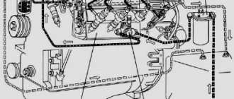
Diagram of the YaMZ-236 diesel power system
Diagram of the YaMZ-236 diesel power system:
A - suction line; B - low pressure; B - high pressure; G - draining excess fuel into the tank;
1 — fuel tank; 2 - high pressure pump; 3 — air filter; 4 —
fine fuel filter; 5 - nozzle; 6 — nozzle sprayer; 7 — fuel priming pump; 8 — manual pump; 9 — oil measuring rod; 10 - drain pipeline; 11 — fuel supply line; 12 — fuel coarse filter; 13 — body; 14 — filter element; 15 - cover; 16 - coupling bolt.
The booster pump 7 sucks fuel from tank 1 through the coarse filter 12 and supplies it through the fine filter 4 to the high-pressure pump 2, from which the fuel is supplied to the injectors 5, which spray it into the combustion chambers of the cylinders.
Atmospheric air enters the diesel cylinders through the air filter and intake manifold. Exhaust gases are discharged from the cylinders into the atmosphere through the exhaust pipe and muffler.
The fuel tanks of diesel cars are designed in the same way as the tanks of cars with carburetor engines.
Fuel filters.
The fuel supplied to the high-pressure pump and injectors must not contain mechanical impurities that could cause damage or increased wear of precision-manufactured parts of the fuel equipment.
Therefore, in the diesel power system, the fuel is filtered many times. The YAME-236 diesel engine has the following fuel filters:
a mesh filter at the end of the fuel intake tube in the tank; coarse cleaning, also located inside the tank and attached to its upper wall; fine cleaning, placed between the booster pump and the high pressure pump; injector filters.
Fuel pre-filter
Coarse fuel filter:
1 - gasket; 2 - plug; 3 - cover; 4 - bolt; 5 — body; 6 — filter element; 7 — receiving tube; 8 — upper wall of the fuel tank.
The coarse filter has a filter element consisting of a mesh frame, on top of which a fleecy cotton cord is wound, and the fine filter has a filter element with mineral wool padding impregnated with an adhesive.
A nozzle 9 is screwed into the hole in the fine filter cover, through which part of the fuel from the filter housing is constantly discharged into the fuel tank through a tube connected to the nozzle. Thanks to this, approximately constant pressure is maintained in the fine filter and the fuel line connecting the filter to the high-pressure pump.
Fine fuel filter
Fine fuel filter:
1 and 8 - plugs; 2 - spring; 3 - rod; 4 - gasket; 5 — body; 6 — filter element; 7 - cover; 9 — jet; 10 - bolt.
The air filter is similar in design and operating principle to inertia-oil air filters for carburetor engines.
The high-pressure fuel pump serves to supply the diesel cylinders with the required amount of fuel under high pressure at strictly defined moments.
On the YaMZ-236 diesel engine, the high-pressure fuel pump is installed between the right and left rows of cylinders (in the “camber” of the cylinder block). The pump shaft is driven into rotation by the drive shaft, the gear of which is meshed with a gear mounted on the diesel camshaft.
The rotational speed of the pump shaft is half the rotational speed of the diesel crankshaft. For two revolutions of the crankshaft, during which one working stroke occurs in each of the diesel cylinders, the pump shaft will rotate one revolution and the pump will inject fuel into all cylinders.
High pressure fuel pump
High pressure fuel pump:
a - cross section and diagram of the operation of the pump section; b - longitudinal section;
1 — manual pump housing; 2 — piston of the manual pump; 3 - cylinder; 4 - rod; 5 — handle; 6 — ring gear; 7 - plunger; 8 — sleeve fastening screw; 9 and 18 - bypass and inlet holes of the sleeve; 10 and 19 — fuel channels of the pump; 11 - sleeve; 12 — valve for air release; 13 — discharge valve seat; 14 — discharge valve; 15 — valve spring; 16 — high pressure fuel line fitting; 17 — pump housing; 20 and 21 - axial and radial drilling of the plunger; 22 — spiral grooves; 23 — gear rack; 24 — rotary sleeve; 25 — protrusion (lead) of the plunger; 26 — plunger spring; 27 — spring support washer; 28 — adjusting bolt; 29 — pusher; 30 — pusher roller; 31 - cam; 32 — pump shaft; 33 — booster pump pusher; 34 — pusher spring; 35 — rod; 36 — piston; 37 — piston spring; 38 — booster pump housing; 39 — automatic injection advance clutch; 40 — bypass valve cap; 41 — centrifugal regulator housing; 42 - stop bracket.
In the housing 17 of the high-pressure pump, a cam shaft 32 is mounted on ball (for the latest pumps - on roller) bearings.
Each of the shaft cams 31 drives a pump section, which is a high-pressure single-plunger pump serving one diesel cylinder. The section consists of a sleeve 11, inside which a plunger 7 is placed, a discharge valve 14 and a roller pusher 29.
The plunger can move up and down in the sleeve.
A support washer 27 of the spring 26 is installed on the groove of the lower end of the plunger, which with its upper end rests through the washer into the pump head. By spring pressure, the support washer is pressed against the adjusting bolt 28 of the pusher 29, and the roller 30 of the pusher is pressed against the cam 31 of the pump shaft.
When the cam protrusion fits under the roller 30, the pusher rises, compressing the spring 26, and moves the pump plunger upward. As the cam lobe rotates out from under the follower roller, the spring returns the plunger and follower to their original position. Thus, during diesel operation, the plunger moves back and forth up and down.
In the upper part of the plunger there are axial 20 and radial 21 drillings. When the plunger is in the sleeve, these drillings connect the space above the plunger with two spiral grooves 22 milled on the side surface of the plunger.
When the plunger is lowered (position I), the space above the plunger of the sleeve, as well as the drillings and grooves of the plunger, are filled with fuel entering the sleeve from channel 19 in the pump housing through the inlet hole 18 of the sleeve. During its upward movement, the plunger first displaces fuel from the sleeve back into channel 19.
After the plunger closes the hole 18 of the liner and the fuel in the liner is in a confined space (position 11), further movement of the plunger will cause a sharp increase in pressure in the space above the plunger. The fuel will open the injection valve 14 and begin to flow through the high pressure fuel line and the nozzle into the diesel cylinder.
Fuel injection continues until the upper edge of the left spiral groove 22 of the plunger approaches the bypass hole 9 of the sleeve (position III). After this, fuel from the space above the plunger will flow through the drillings 20 and 21 of the plunger, the spiral groove 22 and the bypass hole 9 of the sleeve into the channel 10 of the pump housing. The pressure in the space above the plunger will drop sharply, the discharge valve will close, and the fuel supply to the cylinder will stop.
The amount of fuel supplied to the cylinder is regulated by rotating the plunger around its axis, as a result of which the moment of the end of fuel supply by the section changes, while the moment at which the supply begins remains unchanged.
When turning the plunger clockwise (when viewed from above), the edge of its spiral groove approaches the bypass hole 9 of the liner earlier, causing the fuel injection to the nozzle to stop, and the amount of fuel supplied to the cylinder decreases.
Rotating the plunger clockwise until the radial drilling 21 of the plunger coincides with hole 9 of the liner causes a complete cessation of fuel supply to the section (zero supply). When turning the plunger counterclockwise, the edge of the spiral groove of the plunger later reaches hole 9 of the sleeve and the amount of fuel, on the contrary, increases.
To rotate the plunger, a toothed rack 23 and a rotary sleeve 24, mounted on the sleeve, whose gear rim 6 is engaged with the rack, are used. Moving the rack along its axis causes the bushing to rotate, which, in turn, acting through the projections 25, rotates the plunger. The movement of the rack causes the plungers of all sections of the pump to simultaneously rotate at the same angle.
The sleeves of all six sections are secured in the common housing 17 of the pump with 8 screws. Fittings 16 are screwed into the housing from above, pressing the seats of 13 discharge valves to the sleeves. Fuel lines connecting the sections of the high-pressure pump with the injectors are attached to the fittings externally.
Cams 31 of the pump shaft are located so that fuel is supplied in sections in accordance with the order of operation of the diesel cylinders and the accepted intervals between working strokes in different cylinders. The pump shaft 32 is connected to the drive shaft through a centrifugal clutch 39 of automatic injection advance, which increases the advance angle of fuel injection into the cylinders as the diesel crankshaft speed increases.
According to the principle of operation, this clutch is similar to the centrifugal ignition timing regulator of carburetor engines (see Engine ignition system). A gear is installed at the rear end of the pump shaft, which imparts rotation to the shaft located in the housing 41 of the all-mode centrifugal speed controller of the diesel crankshaft. The regulator maintains constant any number of crankshaft revolutions set by the driver by pressing (or releasing) the fuel control pedal and, in addition, limits the maximum number of crankshaft revolutions (2250 - 2275 per minute).
Bearings, pump shaft cams and pushers, as well as regulator parts are lubricated with diesel oil poured into the pump and regulator housings. The plunger pairs of the pump are lubricated with fuel.
The operation of the pump is controlled from the driver's seat using a pedal connected by a system of rods and levers to the regulator lever. The regulator, in turn, acts on the fuel pump rack. To stop the diesel engine, use a button connected by a cable to the regulator stop bracket 42. When the button is pulled out, the bracket rotates down and, through the lever system of the regulator, moves the rack in the direction of reducing the fuel supply to failure, as a result of which the plungers of all sections of the pump are set to the zero supply position.
"Car", under. ed. I.P. Plekhanov
Flywheel
The YaMZ-238 flywheel is made of gray cast iron, dynamically balanced, and bolted to the crankshaft shank. A gear ring (rim) is pressed onto the top of the flywheel for rotation by the starter. Two types of flywheels are manufactured: flat (for a single-disc clutch) and wide (with ebbs, for a double-disc clutch).
| 238-1005115-L Flywheel in Sat. (2-disc clutch) |
| 238-1005115-N Flywheel in Sat. (replacement 238-1005115-K, 1-disc clutch) |
| 236-1005125-B Flywheel rim (115 teeth) |
| 236-1005125-B2 Flywheel rim (132 teeth) |
Connecting rod and piston group
The YaMZ-238 piston is solid cast, made of high-silicon aluminum alloy, may have a ni-resist insert under the upper compression ring, is connected to the connecting rod by a piston pin, the outer surface is made coaxially with the central combustion chamber, with four landing grooves for the piston rings. The piston rings of the YaMZ-238 engine are cast iron, the upper ones are compression rings (the cross-section and coating are different), the fourth is an oil scraper ring with a twisted expander. The YaMZ-238 piston pin is a floating type with retaining rings (limit axial displacement), installed in the piston. Made of cemented steel, hollow. YaMZ-238 connecting rod made of steel, the lower head is split at an angle of 55 degrees, I-beam section, reinforcement at the upper head. The lower head caps are not interchangeable and are made for a specific connecting rod; the cylinder serial number is stamped on the cap and connecting rod on the side of the short bolt; the bronze piston pin bushing is pressed in with further modification. The connecting rod bolts are replaced as a set. The YaMZ-238 piston cooling nozzle is used on turbocharged engines; its design is simple: a housing with a soldered oil supply tube.
| 236-1004005 Sleeve piston |
| 238B-1004005 Sleeve piston |
| 238B-1004005-B Sleeve piston |
| 238NB-1004005-A4 Set of sleeve-piston, piston rings |
| 236-1004002-A4 Set of piston rings (3 pcs) |
| 236-1004020-01 Piston pin (Male) |
| 236-1004022-B Retaining ring |
| 236-1004045-B3 Connecting rod |
| 238N-1011445-A2 Piston cooling nozzle |
Gas distribution mechanism
In accordance with the engine operating cycles and the firing order of the cylinders, the gas distribution mechanism admits air into the combustion chamber and removes exhaust gases. The mechanism is located at the top, two valves per cylinder (one each for intake and exhaust), with a lower camshaft. The YaMZ-238 steel camshaft, with the cams hardened to high hardness. Located in the upper left part of the cylinder block in a special bore. On the YaMZ-238 camshaft, two gears are mounted on a key, from which they receive drives; the drive gears of the high-pressure fuel pump and the fan impellers located in the gear drive of the units are driven by the crankshaft gear. The movement from the camshaft to the YaMZ-238 pusher is transmitted through a roller mounted on needle bearings. The pusher bearings are bronze bushings. To increase strength, a hardened high-quality steel heel is pressed into the pusher, which serves as a thrust bearing for the rods. The pushrods are forged from carbon steel and mounted on a common axis along the engine above the camshaft. The pusher axis is hollow for supplying oil to the rocker arm bearings and consists of three separate parts. YaMZ-238 push rods (rocker arms) are made of hardened steel. Rocker arms made of steel, stamped with a bronze bushing. The valves are made of heat-resistant steel, installed in universal bushings that serve as guides, and sealed with cuffs. Each valve is equipped with two cylindrical springs (with right and left direction of turns). A special lock is used to secure the springs, which creates rotation of the valves when the engine is running, which increases the life of the valve. The springs, due to their elasticity, close the valves and press them with force against the seat. Thermal clearances of the valves are subject to adjustment.
Connection diagram
When installing the injection pump on the power unit, you must pay attention to ensure that the marks of the drive coupling half and the injection advance are at the same level. It is necessary to correctly set all axial clearances between the cams and the ends of the couplings and coupling halves before finally tightening the mounting bolts. The size of the gaps should not exceed 0.3 mm. After installing the adjusted fuel injection pump on the engine, the fuel supply lines should be connected.
The main feature of the high-pressure fuel pump connection diagram is the correct sequence of connecting the fuel lines and injectors.
Lubrication system
Oil crankcase YaMZ-238 stamped steel, wet type. The movement of lubricants from the intake is carried out by a two-section gear-type oil pump YaMZ-238. One section of the pump supplies oil to the system through a series-connected coarse filter, then the oil returns by gravity to the crankcase. The second section supplies lubricant to the oil cooler (attached to the water cooler) for cooling and return to the crankcase. In addition, on many engines, for fine oil purification, a centrifugal purification filter (oil centrifuge) is installed, in which the oil is spun, and due to centrifugal force, all mechanical impurities are separated from the oil. After cleaning, the oil enters the main line located in the cylinder block and is then transferred to the lubricated surfaces. A valve system is used to maintain constant pressure in the system.
| 238-1009010-A Oil crankcase |
| 238В-1009010-А2 Oil crankcase (with housing) |
| 238N-1009010-A2 Oil crankcase |
| 236-1011014 -G Oil pump |
| 238-1011398-B2 Oil intake pipe |
| 238B-1011056 Pressure reducing valve |
| 236-1012023-A Oil filter element GO |
| 236-1028010-A Oil purifier |
| 236-1028031-A2 Centrifuge axis |
Fuel supply system design
The design of the fuel supply system for the power unit consists of the following elements:
Let us briefly describe the principle of operation of the fuel supply system. The fuel pump supplies it to the injection pump through coarse and fine filters. In accordance with the operating mode of the power unit, the injection pump injects the working mixture into the engine cylinders through injectors. The fuel system circuit is designed in such a way that excess mixture flows back into the tank through the main pipes.
Operating principle of fuel injection pump YaMZ-238
The pump has compact dimensions and is located in the engine compartment on the plane of the power unit, between the rows of cylinders. The injection pump has eight sections (one for each cylinder) and a gear drive. The fuel pump, depending on the engine power, comes in several types, each of which has its own design features and adjustment method.
The operating principle of the injection pump is not complicated, but has certain nuances. To create primary pressure, the system is equipped with a fuel pump, which supplies the working mixture to the fuel injection pump chambers, with the plunger in the lower position. As soon as the plunger begins forward movement, upon reaching a certain position, it opens the discharge valve to further supply the mixture and inject it. The pressure in the fuel chamber increases due to the upward movement of the plunger.
When the maximum pressure is reached, the nozzle needle rises and the working mixture begins to flow into the cylinder. As soon as the plunger reaches its final upper position, the pressure of the working mixture in the discharge circuit will begin to decrease sharply. As a result, the injector needle will return to its initial position and fuel injection will stop.
One of the most common fuel injection pump malfunctions is a worn oil seal. In this case, the repair is not difficult and you can do it yourself. On the Internet you can find a video with a detailed description of the working process.
Cooling system
The cooling system serves to remove heat from the cylinder walls, piston, cylinder heads, valves, injectors and other parts that heat up from contact with hot gases and due to friction, and to maintain acceptable temperatures in them. The cooling system is closed, liquid, consisting of a YaMZ-238 centrifugal water pump, with a built-in thermostat, gear drive and fan. The coolant flows in a small circle until it reaches 82°C, from 83 to 98 degrees the valve gradually opens, then circulation occurs in a large circle. A water radiator and an air-to-air charge air cooler (necessary for some engines) are mounted on the vehicle.
| 236-1307010-A3 Water pump (old model) |
| 236-1307010-B2 Water pump |
| 238AK-1307010 Water pump |
| 238-1003290-B Right water pipe |
| 238-1003290-D Right water pipe (under KEM) |
| 238-1003291-B Left water pipe |
| TS107.1306100-06M Thermostat |
| 238B-1013600 Liquid-oil heat exchanger |
Fan and fan drive
The YaMZ-238 fan drive is installed in the frontal part of the cylinder block, above the axis of rotation of the crankshaft, driven by a gear transmission, a fan with an impeller made of metal or plastic (for a number of engines with a built-in viscous coupling).
| 238-1308011-B2 Fan drive |
| 238-1308011-G2 Fan drive |
| 238БК-1308011-Д Fan drive |
| 238NB-1308011-G Fan drive |
| 238NB-1308011-D Fan drive |
| 238ND-1308011-V Fan drive |
| 238AK-1308025 Fan drive pulley |
| 238NB-1308025 Fan drive pulley |
| 238-1308012-A4 Fan impeller |
| 238AK-1308012 Fan impeller |
| 238BE-1308012-A Fan impeller |
| 238N-1308012 Fan impeller |
| 238NB-1308012-B2 Fan impeller |
Replacing the Yamz 238 injection pump drive
Repair of the YaMZ-238NE engine. Fan drive installation. Reasons for frequent bearing failures. Read more
The bearings of the YaMZ 7511 fuel injection pump drive were brokenRead more
Replacing the seal of the YaMZ 238M fuel injection pumpMore
Yamz 7511 or 6581 tears the plates - the washers of the injection pump drive. video 1.More details
installation of the injection pump drive on the Yamz 7511 motor. Yamz 238More
Yamz 7511 installation of fuel injection pump drive. life hack.More details
replacement of Yamz 238 fan driveMore
Dz98 motor grader. Replacing the fuel injection pump drive bearing on YaMZ-238.More
Grader DZ-98. Replacing the bearings of the fuel injection pump drive with Yamz-238.More
Repair of fuel injection pump of YaMZ-238 engineMore details
MAZ-5432. Oil leaks from the seal of the YaMZ-236 BE 2 injection pump drive. What to do? More details
MAZ. We change the oil seals on the injection pump drive. YaMZ-236 BE 2More details
REPLACING THE SEAL OF THE FUNCTION DRIVE DRIVE. Kamaz.More details
Replacing plunger sealing rings on fuel injection pump Euro 2 YaMZ 236 MAZ 5551More
Maz 5440 injection pump drive oil sealRead more
Yamz 238 removal of fuel equipmentRead more
Source
Fuel supply system
Mechanical fuel system - a high-pressure fuel pump (HPFP) manufactured by YAZDA controls the fuel supply. The system operation scheme is standard: fuel from the tank passes through the line to the coarse fuel filter (sump), then to the fine filter, through it to the injection pump. The fuel injection pump creates a large excess pressure and delivers fuel to the injectors in a pulsed flow through the high-pressure fuel lines; under fuel pressure, the injector needles begin to rise upward, and fuel is injected. The injector turns the liquid into a mist, and a hydraulically controlled needle accurately meters the amount of fuel to each cylinder. Excess fuel is discharged through the fuel drain line into the supply tank.
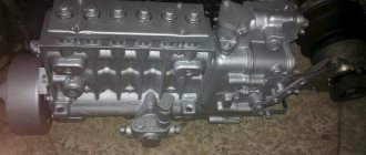
| 80.1111005-30 injection pump |
| 173.1111005-30 injection pump |
| 236-1106288-B Fuel pump assembly) |
| 236-1029122-A Driven gear of the injection pump drive |
| 236-1029268-G Injection pump drive half-coupling |
| 236-1029300-B Injection pump drive coupling |
| 60.1121010-12 Fuel injection advance clutch assembly |
| 26.1112010-04 Nozzle |
| 236-1112163-B2 Injector mounting bracket |
| 261.1112010-04 Nozzle |
| 261.1112010-13 Nozzle (new sample) |
| 267.1112010-01 Nozzle |
| 238-1104308 Fuel injection pump pipe (straight L-455mm) |
| 236-1117010-A4 FTOT Fine fuel filter assembly |
| 7511.1117010 FTOT Fine fuel filter assembly (new sample) |
| 204A-1105510-B FTOT Coarse fuel filter assembly |
How to remove the Yamz 238 injection pump drive
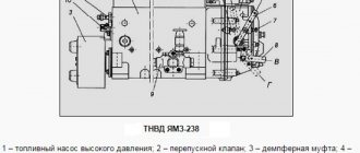
Fig. 9 – Drive of the high pressure fuel pump YaMZ-238DE2, 238B, 238DE
1 – driven gear; 2 – driven gear axis; 3–cuff; 4–flange of the coupling half; 5–drive coupling half; 6–bolt; 7–washer; 8–bolt; 9–bolt; 10–cuff; 11–bolt; 12–spring ring; 13–thrust flange; 14–special nut; 15 plates.
Using pliers, remove the spring ring (Figure 9, item 12).
Remove the drive coupling half (item 5), unscrew the bolts (item, remove the driven gear (item 1) and the cuff (item 10) from the axis of the driven gear (item 2).
Unscrew the bolts (pos. 9) and remove the thrust flange (pos. 13).
Remove the driven gear axis (item 2) with the bearing assembly and cuff (item 3) from the cylinder block.
Unscrew the nut (pos. 14) from the axis of the driven gear (item 2) using a special wrench.
Driven gear axis subassembly:
Install the bearing assembly on the axis of the driven gear (2).
Screw the nut (14) onto the axis of the driven gear with the bearing assembly using a special wrench.
Install the cuff (item 3) onto the axis of the driven gear with the bearing assembly.
Installation of the YaMZ-238 fuel pump drive D, DE, AK, M2, B, ND
Blow out the M10 hole for fastening the driven gear axis with the bearing and cuff with compressed air. Apply 2-3 drops of sealant (UG-9 TU 6-01-1326-86) into 3 holes (M10) in the front end of the block.
It is allowed to apply sealant to the bolt threads. Install the driven gear axis with the bearing and cuff assembly into the bore of the cylinder block until the flange stops at the front end of the block.
The axle should fit freely. Pressing the axle is not allowed; it is allowed to install the axle with light blows of a hammer through a mandrel to eliminate distortions.
Apply 2-3 drops of UG-9 sealant into the M10 threaded holes of the driven gear axis flange (item 13); it is allowed to apply sealant to the threads of the driven gear axis flange mounting bolts (M10 bolt 9 pcs.).
Install the driven gear (item 1) on the axle flange, aligning the holes of the gear and the axle flange, screw in the fastening bolts 2-3 threads by hand.
Holding the gear from turning, tighten the bolts finally with Mkr = 53.9-68.6 Nm (5.4-7.0 kg/cm) (S = 14).
Assembly and installation of fuel injection pump on the YaMZ-238 D, DE, AK, M2, B, ND engine
Using the injection pump hanger and the crane beam, install the injection pump on the workbench.
Assemble the tip (236-1104430, 1 pc.) with a bolt (M14, 310096-P2) and washers (312236-P34, 2 pcs.), screw the bolt into the fuel pump by 2-3 threads by hand.
Assemble the outlet tube (238BM-1104384, 1 pc.) with the bolt-valve included in the injection pump and sealing washers (312326-P34, 2 pcs.), screw the bolt-valve into the injection pump by 2-3 threads by hand.
Assemble the brackets: upper (236-1104440, 1 pc.) and lower (236-1104441, 1 pc.) with bolts (M6, 201422-P29, 2 pcs.), washers (252134-P2, 2 pcs.) and gasket (236-1104457-B, 1 pc.); fasten the low-pressure pipes with brackets to each other, move the brackets as far as possible towards the injection pump (S=10).
Completely tighten the bolts securing the fuel pipes and tip (S=19). The fuel pipes should not touch the fuel injection pump body or each other, and the tip should be positioned vertically.
Insert the bolts (M10, 201461-P29, 4 pcs.) securing the fuel pump with washers (312515-P29, 4 pcs.) into the holes of the pump supports, align the mark on the damper with the mark on the indicator, while the bosses on the damper should be positioned horizontally.
Place the flange of the drive coupling half with plates (1 piece) assembled onto the drive shaft of the injection pump 238DE2, 238ND5, 238AK.
Air intake system
The YaMZ-238 air intake system is designed to supply the air mixture to the combustion chambers.
| 236-1115021 Intake manifold |
| 236-1115021-B Intake manifold right |
| 238-1115021-B Intake manifold |
| 238B-1115021-B Intake manifold |
| 238NB-1115020-B Intake manifold |
| 238NB-1115021-B Intake manifold |
| 238F-1115032 Connecting pipe for intake manifolds |
Turbocharging
Turbocharging is designed to increase engine power performance. By increasing the pressure, we increase the amount of oxygen in the cylinder and promote the combustion of more fuel. A charge air cooler (intercooler) installed on a vehicle allows you to maximize air density by extracting heat from the flow. The turbocharger (TCR) of the YaMZ-238 engine has a radial centripetal turbine and a centrifugal compressor.
| 238NB-1118010-B Turbocharger |
| TKR-100 Turbocharger (YaMZ-238B/BE/BE2/7511/658 EURO-3 replacement K36-30-04) |
| TKR 100 Turbocharger (YaMZ-238B/BE/BE2/7511/658 EURO-3 replacement K36-30-04) |
| 238F-1115128-B Turbocharger inlet pipe |
Electrical equipment
The electrical equipment system is single-wire, direct current with a rated voltage of 24V. The negative pole of the current source is connected to the housing. The starter is used to start the engine, the generator is used to provide power to equipment systems and maintain the battery charge.
| 2501.3708-21 Starter (new 10 teeth) |
| 2501.3708-40 Starter (11 teeth old style) |
| 2501.3708.150-01 Coil (starter stator winding) |
| 2501.3708.200-03 Starter anchor (old model 52 cm) |
| 2501.3708.800 Relay for starter (25-3708-21/40) |
| 2501.3708.200-21 Starter anchor (new sample 50 cm) |
| 2502.3708.320-11 Starter cross-beam (new model) |
| 2502.3708600-10T Starter drive (Bendix 10 teeth) |
| 2502.3708600 Starter drive (Bendix 11 teeth) |
| 236-3708702-B Starter bracket (upper) |
| 236-3708704-B Starter bracket (lower) |
| 236-3708704-B Starter bracket (lower) |
| 1312.3771 Generator 28V 60A |
| 1322.3771 Generator 28V 50A |
| 1702.3771 Generator 28V 60A |
| 236-3701774 Generator bracket |