Article navigation
Connection diagram
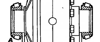
Shaft 11 rotates in a roller bearing, which is installed in the housing cover of the UAZ 469 wheel reducer, and in a bronze bushing inside axle 18. At the end of shaft 11 there is a mechanism for disconnecting the front wheels of the vehicle. The device consists of movable rods 14 and 15, which are located on the splines of the shaft and bolts 17 and 16 with a spring and a ball.
These movable couplings are connected by their external splines to the internal splines of the drive flanges 13 and 14, which are bolted to the wheel hubs. To reduce wear on the metal surfaces of the front axle parts of the UAZ 469 and save fuel when driving on paved roads, it is recommended to disconnect the front wheel hubs at the same time as disconnecting the front drive axle.
To perform this disconnection, remove the protective caps 16 and 18. Then unscrew the screws 16 and 17 from the hole in the shaft 11. Place the coupling in such a position that the groove of the signal ring “a” on its plane is in the same plane with the end of the flange. When the coupling is installed in the required position, tighten the protective caps.
The wheels must be secured by screwing in bolts 16 and 17. The bolts must be tightly tightened. Disabling and enabling must be done simultaneously on two wheels of the front drive axle. DO NOT engage the front axle with the wheels disabled!
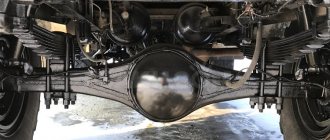
Repair and adjustment of the rear axle UAZ-3962, UAZ-3741
Maintenance of the rear axle of UAZ-3962, UAZ-3741
Maintenance of the rear axle of the UAZ-3741, UAZ-3962 consists of maintaining the oil level in the crankcase and timely replacing it, checking the seals, timely detection and elimination of axial clearances in the final drive gears.
Periodically clean the safety valve and tighten all fasteners.
If the oil in the crankcase is heavily contaminated or there are metal particles in it, wash the crankcase with kerosene before adding fresh oil.
To flush, pour 1-1.5 liters of kerosene into the crankcase; lift the wheels, start the engine and let it run for 1-1.5 minutes, then drain the kerosene and fill with fresh oil.
Axial clearance of the drive gear of the main gear of the rear axle gearbox of UAZ-3962, UAZ-3741 is not allowed. Check the clearance by rocking the drive gear by the driveshaft mounting flange.
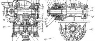
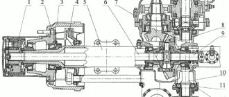
Rice. 8. Rear axle UAZ-3962, UAZ-3741
1-safety valve; 2-differential bearing; 3.8-adjusting shims; 4-rear drive gear bearing; 5-adjusting ring (not installed since 1991); 6-oil ring; 7-nut; 9-drive gear; 10-front drive gear bearing; 11-thrust washer of the side gear; 12 driven gear
Axial clearance of the driven gear of the main gear of the UAZ-3962, UAZ-3741 rear axle gearbox is not allowed. Check it by moving the gear through the oil filler hole.
To eliminate the gap, add sets of shims of equal thickness between the ends of the differential and bearings.
Do not add shim sets of different thicknesses or install them on the same side of the driven gear because this will lead to disruption of the engagement of worn-in gears and their rapid breakdown.
Dismantling the rear axle of UAZ-3962, UAZ-3741
Disassemble the rear axle of UAZ-3741, UAZ-3962 in the following order:
— Place the bridge on the stand, unscrew the oil filler and oil drain plugs and drain the oil.
— Unscrew the bolts securing the axle shafts and, using them, remove the axle shafts.
— Unscrew the nuts and bolts securing the cover and crankcase, carefully separate the bridge into two parts. Remove the gasket.
— Remove the differential and driven gear assembly from the crankcase.
— Remove the main gear drive gear. Without disassembling the bridge, it is impossible to remove the drive gear, since when pressing the gear and bearing assembly out of the gearbox housing of the UAZ-3962, UAZ-3741 bridge, the rear bearing (with cylindrical rollers) will rest against the driven gear.
— To remove the drive gear, unscrew and unscrew the nut on the shank, remove the washer and flange, unscrew the bolts and remove the drive gear front bearing cover.
— Remove the oil sump ring and use a tool to press the drive gear and bearing assembly out of the crankcase.
Disassemble the rear axle differential of UAZ-3962, UAZ-3741 in the following order:
- Unscrew the bolts securing the driven gear to the satellite box;
- remove the driven gear;
- Unscrew the bolts securing the halves of the satellite box;
— disconnect the right half of the gearbox from the left and remove the differential gears, satellite axles and support washers.
Assembly and adjustment of differential bearings for UAZ-3962, UAZ-3741 bridges
Assemble the rear axle differential in the following order:
— Before assembling the differential, lubricate the axle gears, pinions, thrust washers and pinion axles with transmission oil.
— Install thrust washers on the journals of the axle gears.
— Install the axle gear with thrust washer assembly into the left gear box.
— Install the satellites on the axis of the split cross.
— Install the split crosspiece with satellites into the left gearbox of the differential.
— Install the axle gear with thrust washer assembly into the right gear box. Holding the axle gear, install the right satellite cup onto the left one so that the marks of both cups are aligned.
— For the assembled differential, the axle gears must be rotated using a splined mandrel from a force of no more than 59 N (6 kgf) applied over a radius of 80 mm.
Adjust the differential bearings of the rear axle of UAZ-3962, UAZ-3741 (if they are replaced) in the following order:
— Press the inner rings of the differential bearings onto the journals of the assembled differential so that there is a gap of 3.5-4.0 mm between the ends of the gearbox and the ends of the inner rings of the bearings.
— Install the differential assembly into the crankcase, then the gasket and crankcase cover and, turning the cover by the casing, roll the bearings so that the rollers are in the correct position. Then use bolts and nuts to evenly connect the cover to the crankcase.
— Unscrew the bolts again, carefully remove the cover, remove the differential from the crankcase and use a feeler gauge to measure the gaps between the ends of the inner rings of the bearings and the gearbox.
— Remove the inner rings of the differential bearings. Divide the selected pack of gaskets approximately in half. Install the gaskets on the journals of the satellite gearbox and press the inner rings of the bearings until they stop.
Assembling and adjusting the bearings of the drive gear of the rear axle gearbox UAZ-3741, UAZ-3962
Assemble and adjust the bearings of the drive gear of the rear axle gearbox in the following order UAZ-3962, UAZ-3741:
— Press the bearings onto the drive gear. After pressing on the rear support bearing with cylindrical rollers, open the end of the shank onto which it is pressed.
— Place the spacer sleeve and shims for the front bearing (double-row bevel) of the drive gear between the inner rings.
— Install the adjusting ring 5 (see Fig. 8) of the drive gear 9 (not installed since 1991).
— Press the drive gear assembly with bearings into the rear axle gear housing until it stops and adjust the front bearing preload by changing the thickness of the gasket pack 8 and tightening the nut 7 until it stops.
— In this case, the oil sump ring 6 and the flange must be installed on the gear shaft, and the front bearing cover must be removed so that the friction of the cuff on the flange does not affect the measurement readings. To reduce the tension, add spacers, to increase it, remove it.
After completing the adjustment, remove the flange and install the gaskets and drive gear front bearing cap.
Assembly of the rear axle UAZ-3962, UAZ-3741
Assemble the rear axle after adjusting the gear engagement of the UAZ-3741, UAZ-3962 gearbox in the following order:
— Install the gasket pack between the end of the front pinion bearing cap and the crankcase. The thickness of the package should be 1.3 times the gap between the ends of the cover and the crankcase. If necessary, increase the thickness of the bag by 1.4 times.
— Install the drive gear front bearing cover with cuff assembly and secure with bolts.
— Install the differential with the driven gear and bearings assembly into the rear axle gear housing.
— Install a gasket between the crankcase and the cover.
— Install the crankcase cover so that both spring pads are at the top of the axle. Connect the cover and crankcase using bolts and nuts.
— While turning the drive gear, check for any jamming or snagging in the assembled axle.
After assembling the bridge, check its heating while the vehicle is moving. If the crankcase gets very hot, check that the bearings are adjusted correctly.
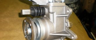
Hinge
The constant angular velocity joint is located in the inner cavity of the steering knuckle. This mechanism corresponds to the specified angular velocities between the drive and driven shafts, which are constantly changing. It is important to keep this angle the same regardless. The front axle hinge of the UAZ-469 consists of two forks. Four balls are placed in grooves of a curved configuration.
The fifth ball is placed in the central sockets of the forks. This is an installation element, its function is to center the forks. The longitudinal movement of the hinge is limited by ball bearing 10 and thrust washers 25 and 26. The drive fork of the hinge located inside is connected by splines to the differential side gear.
At the end of the outer driven fork there is a drive gear 21 of the wheel reducer. It is mounted on splines that serve only the steering knuckle. The roller bearing is also located here. At the same time, these parts are locked with nut 19. The driven gear of the internal gearbox is bolted to shaft 11.
Blog about UAZ
Adjustment of the gaps in the meshing of gears and in the bearings of the drive axle of UAZ-3741, UAZ-3962, UAZ-3909, UAZ-2206, UAZ-3303 cars is carried out only when replacing gears or bearings, or when axial clearance appears in the driving or driven gears of the main transfers. Replacement of main gears should only be done as a complete set.
Adjusting the bearing of the drive gear of the main gear of the drive axle UAZ-3741, UAZ-3962, UAZ-3909, UAZ-2206, UAZ-3303.
Adjustment of the bearing of the drive gear of the main drive of the drive axle must be done by selecting the thickness of the shim pack and tightening the flange nut. The bearing must have such a preload that there is no axial movement of the drive gear and the gear can be rotated by hand without much effort.
Check the bearing preload with a dynamometer. At the same time, disconnect the left half of the crankcase. Remove the drive gear bearing cap so that cuff friction does not affect the dynamometer readings. With proper adjustment, at the moment of turning the drive gear by the hole in the flange, the dynamometer should show a force of 1.5-3 kgf for run-in bearings and 2.0-3.5 kgf for new bearings.
If axial play of the drive gear appears during vehicle operation, tighten the flange nut. If the axial play is not eliminated, then reduce the thickness of the shim pack and adjust the bearing as indicated above.
After adjustment, monitor the heating of the bearings while driving. A slight heating of the bearing is not dangerous, but if the neck of the drive axle crankcase heats up to a temperature of 90 degrees or higher, the water on the crankcase boils, this means that the bearing has been overtightened and the overall thickness of the gaskets should be increased.
This is interesting: Design and adjustment of the VAZ 21083 carburetor
Adjusting the differential bearings of the drive axle UAZ-3741, UAZ-3962, UAZ-3909, UAZ-2206, UAZ-3303.
Adjustment of the differential bearings must be done by selecting the thickness of the package of adjusting shims installed between the ends of the inner rings of both bearings and the gearbox. When replacing main gears and differential bearings, make adjustments in the following sequence:
1. Press the inner rings of the differential bearings onto the journals of the assembled differential so that there is a gap of 3-3.5 mm between the ends of the gearbox and the ends of the inner rings of the bearings.
2. Remove the axle shafts and install the differential assembly with the driven gear into the crankcase, install the gasket and cover, tighten the cover mounting bolts and, turning the driven gear with a mounting blade through the neck of the crankcase, roll the bearings so that the rollers take the correct position. Then use fasteners to evenly and completely connect the cover to the crankcase.
3. Unscrew the fasteners again. Carefully remove the cover, remove the differential from the axle housing and use a feeler gauge to measure the gaps A and A1 between the ends of the gearbox and the ends of the inner rings of the bearings.
4. Select a package of gaskets with a thickness equal to the sum of gaps A+A1. To ensure preload in the bearings, add a 0.1 mm thick spacer to this package. The total thickness of the gasket package should be A+A1+0.1 mm.
5. Remove the inner rings of the differential bearings. Divide the selected pack of gaskets in half. Install the gaskets on the journals of the satellite gearbox and press the inner rings of the bearings until they stop. After this, adjust the side clearance by moving the driven gear.
When replacing only the differential bearings, measure and compare the height of the new and old bearing assemblies. If the new bearing is higher or lower than the old one by some amount, then reduce the thickness of the existing gasket package in the first case and increase in the second case by the same amount.
Adjustment of the side clearance and position of the main gears of the drive axle UAZ-3741, UAZ-3962, UAZ-3909, UAZ-2206, UAZ-3303.
Adjustment of the side clearance and position of the main gear gears must be done only when replacing old gears with new ones in the following sequence:
- first adjust the drive gear bearings and differential bearings as indicated above, - then proceed to adjust the lateral clearance in the meshing of the final drive gear teeth.
The lateral clearance in the meshing of the gears must be adjusted by moving the shims from one side of the differential box to the other. If you remove shims from the side of the driven gear, the gap in the mesh increases, but if you add shims, the gap decreases. The gaskets only need to be rearranged without changing their total thickness, so as not to disturb the tension of the differential bearings.
The circumferential side clearance should be in the range of 0.35-0.77 mm. Measure on the flange of the drive gear at a radius of 40 mm, check in four positions of the drive gear after each revolution. Having finished assembling the drive axle, you need to check its heating after the car is moving.
If the heating of the crankcase in the area of the double-row bevel bearing, drive gear or differential bearings is over 90 degrees, the water on the crankcase is boiling, then it is necessary to increase the total thickness of the package of selected gaskets for the double-row bevel bearing of the drive gear. And for differential bearings, reduce the thickness of the gaskets on the crankcase side, with a circumferential side clearance of 0.64 mm or more, or on the cover side, with a circumferential side clearance of less than 0.64 mm.
Maintenance
Maintenance allows you to maintain the front drive axle of the vehicle in working condition. Thanks to maintenance, the wear rate of parts and components is reduced. It is important that when it is carried out, the occurrence of malfunctions is prevented; they are identified at an early stage for timely elimination.
- daily – EO;
- first – TO-1;
- second – TO-2;
- seasonal – CO.
The frequency of maintenance-1 and maintenance-2 is regulated by GOST 21624-81.
| Operating Condition Categories | Maintenance frequency, km | |
| TO-1 | TO-2 | |
| I | 4000 | 16000 |
| II | 3600 | 14000 |
| III | 3200 | 12000 |
| IV | 2800 | 11200 |
| V | 2400 | 9600 |
Assembling and adjusting differential bearings
Assemble the differential in the following order:
- Before assembling the differential, lubricate the axle gears, pinions, thrust washers and pinion shafts with transmission oil.
- Install thrust washers onto the journals of the axle gears.
- Install the axle gear and thrust washer assembly into the left gearbox.
- Install the satellites on the axis of the split cross.
- Install the detachable crosspiece (Fig. 168) with satellites in the left satellite box.
Rice. 168. Installation of a detachable cross with satellites in the left satellite box
Install the axle gear with thrust washer assembly into the right gear box. Holding the axle shaft gear, install the right satellite cup on the left one so that the marks (Fig. 169) (ordinal numbers) of both cups are aligned.
Rice. 169. Installation of satellite boxes according to marks
- Connect the halves with bolts and tighten them. Tightening torque 32-40 N*m (3.2-4.0 kgf*m).
- Install the main drive driven gear onto the gearbox, aligning the bolt holes. Install the bolts and tighten them. Tightening torque 98-137 N*m (10-14 kgf*m).
For the assembled differential, the axle gears must be rotated using a splined mandrel from a force of no more than 59 N (6 kgf) applied over a radius of 80 mm.
Adjust the differential bearings (if they are replaced) in the following order:
- Press the inner rings of the bearings (Fig. 170) of the differential onto the journals of the assembled differential so that there is a gap of 3.5-4.0 mm between the ends of the satellite box and the ends of the inner rings of the bearings.
Rice. 170. Pre-pressing of the inner rings of the differential bearings
Install the differential assembly into the crankcase, then the gasket and crankcase cover and, turning the cover by the casing, roll the bearings so that the rollers take the correct position (Fig. 171). Then use bolts and nuts to evenly connect the cover to the crankcase.
Rice. 171. Rolling differential bearing rollers
Unscrew the bolts again, carefully remove the cover, remove the differential from the crankcase and use a feeler gauge to measure the gaps A and A1 (Fig. 172 and 173) between the ends of the inner rings of the bearings and the gearbox.
Rice. 172. Clearance measurements when adjusting differential bearings
Rice. 173. Gaps A and A1 between the ends of the inner rings of bearings and the satellite box
UAZ rear axle bulkhead
To assemble a “military” (with final drives) bridge, you need to perform the following steps:
A)
Pressing in the outer rings of all bearings and assembling the satellite box:
1) Completely clean the inside of the axle halves from old oil and dirt. Wash the bridge cavities with solvent.
2) Press the outer rings of the differential bearings into both halves of the axle. Pressing is carried out through a spacer sleeve, for example, an old outer ring of a bearing
3) Press the outer rings of the drive gear bearings into the axle housing.
Outside, you can use 10mm plywood as a spacer
To make pressing easier, you can apply a couple of drops of oil to the outer rings of the bearings and rub them with your finger over the entire surface.
All outer rings are pressed until they are fully seated.
4) Press the bearings onto the journals of the satellite box so that there is a gap of 3-4mm between the ends of the bearings and the satellite box
Be careful when you press on the second bearing. You cannot rest the gearbox on an already pressed bearing, because... it may shift. That is, as shown in the photo, you cannot press on the second bearing.
5) Install the gear box with bearings into the axle housing. Rotate one of the axle halves (the smaller one, the so-called “stocking”) relative to the axle housing to self-install the bearing rollers.
6) Disassemble the bridge again. Remove the satellite box and use a set of feeler gauges to measure the distances between the ends of the bearings and the satellite box (the previously set gap is 3-4mm). Let's call these distances A and A1. Using the formula B = A + A1 + 0.1, we calculate the required thickness of the gaskets.
7) We divide this distance B approximately in half. Accordingly, we assemble 2 sets of shims. It is advisable to assemble a package of thin gaskets. Gaskets come in thicknesses of 0.1mm, 0.15mm, 0.25mm and 0.5mm. It is better to measure the two packs of gaskets assembled in this way with a micrometer in order to make sure the sizes match.
We press the bearings (only a two-legged puller is suitable; in the satellite box there are 2 special recesses for its legs)
And install under each selected gasket package
B) Assembling the drive gear (we do not install the gearbox in the axle housing yet):
1) Using a micrometer, measure the height of the old bearing closest to the drive gear teeth. Measure the height of the new bearing. Let's call the difference in height between the new and old bearings the value “A”. If the old bearing is lower than the new one by the amount “A”, then it is necessary to increase the thickness of the adjusting washer located between this bearing and the teeth of the drive gear. If the new bearing is lower than the old one, then increase the height of this washer by this value “A”. The washers are produced in increments of 0.05mm.
If the height of the bearings is the same, then you can install the old washer.
This is interesting: We personally repair rotten car sills
2) Place the selected (or old) washer and press the new bearing onto the drive gear shaft. Next, install a new spacer sleeve and another adjusting washer. The height of the new and old spacers must also be measured. If they are different, then you cannot install the old shim (which is located between the spacer sleeve and the outer bearing). It is necessary to select this washer so as to compensate for the difference in the height of the spacer sleeves. The height of the new bushing is less, then the adjusting washer should be thicker by this amount. And vice versa.
3) Install the drive gear into the axle housing, press on the second bearing, install a washer with an internal sprocket, DO NOT INSTALL the oil seal, but install a flange. The oil seal cannot be installed because it will distort when measuring the breakaway torque.
5) If the breakaway moment is greater, then it is necessary to add shims between the outer bearing and the spacer sleeve. And vice versa. The spacers come in 0.05mm increments.
6) Mark the relative position of the nut and flange. Remove the flange and press in the drive gear oil seal. Install the flange.
7) Tighten the flange nut until the marked position is achieved again. We pin it.
B) Adjusting the GP gap:
1) Install the gearbox with adjusted bearings into the axle housing (the drive gear is already installed). Next, we apply paint (you can use any paint, but there are special ones on sale for adjusting the side clearances) on the teeth of the driven (large) gear.
2) Rotate the flange in both directions long enough.
3) We disassemble the bridge. And look at the contact patch that appears on the paint.
Drawings of correct and incorrect spots should be looked at in the manual.
4) If the lateral clearance spot of the GP is incorrect, then by rearranging the gaskets under the bearings of the satellite box, the satellite box is moved closer and further from the drive gear
By changing the thickness of the gasket under the large bearing of the drive gear, it thereby moves deeper into the bridge (i.e. closer to the satellite box) or outward. The thicker the washer, the more the drive gear extends outward and vice versa.
5) Having achieved the correct contact patch, you can install the axle shafts and assemble the final drive.
Features of unit dismantling
When removing the rear axle, you need to unscrew the tail unit nut, remove the washer, mating flange, cover of the front gear roller assembly, and press the assembled gear with bearings out of the oil cooler at the rear of the car.
This circuit is excellent for disassembling a differential device. The next step is to unscrew the splines connecting the driven gear to the gearbox and reset it. Divide both parts of the box, pull out the gears, planetary gear rods, and support nuts. When assessing disassembly, pay attention to the integrity of the gear wheel teeth. If they are damaged, the part must be replaced. To remove rollers, outer and inner rings, special tools are required. Strictly study and understand the disassembly sequence so that you can accurately perform all steps in reverse order when reassembling.
This is interesting: Tips that can help you charge your battery properly
When inspecting the oil stripper ring, check for surface irregularities. If yes, process to a thickness of 5 mm. The same goes for the cardan flange. Grinding height up to 53 mm. Wash the protective surfaces. Blow out the oil outlets. Drive design parts and axle shafts should be replaced if there are scuff marks or severe wear.