Kamaz family vehicles continue to operate successfully on Russian roads to this day. Many of the cars are in private hands, and their owners will sooner or later need Kamaz electrical wiring to find the cause of the failure of one or another electronic component.
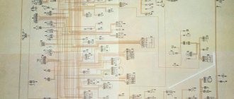
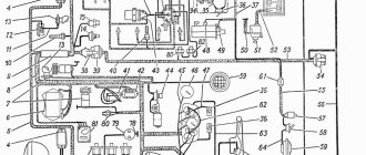
General wiring diagram for Kamaz models 5511, 5410, 5320
The electrical equipment of Kamaz family vehicles consists of various systems operating together:
- Power supply systems for all electronic devices and components operating from the vehicle’s on-board network;
- Engine starting systems;
- Vehicle exterior and interior lighting systems;
- Instrumentation systems;
- Heating systems, control of windshield wipers and windshield washers;
- Light and sound alarm systems (if installed on the vehicle).
Composition of KamAZ electrical equipment
The electrical equipment of the machine consists of the following units:
- Power supply system.
- Light and sound warning alarm.
- External and internal technical lighting.
- Control, measuring and recording equipment.
- Heating system.
- Trigger mechanism.
Original electrical equipment and wiring diagram KAMAZ-55111
Technical features
Like any mass-produced vehicle, the Kamaz family has differences not only in the chassis, but also in the electrical system (as in the Gazelle wiring diagram).
In particular, a number of models were equipped with:
- 800 W generator;
- 2 kW generator.
Modification with 800 W generator
The wiring on a KamAZ of this modification differs from other models, since a G273-A alternating current generator is installed on it:
- Power 800 W;
- Rated voltage 28 V;
- equipped with a built-in rectifier BPV4-45;
- integrated voltage regulator YA12OAT.
Among the features, it should be noted that the phase windings of the stator are connected in a star configuration.
- The zero point of the winding is output for a supply voltage of 14 V.
- A rotor from a 14-volt generator is installed on the generator, since it is possible to reduce the overvoltage during load shedding by half.
Power supply system
The power supply is intended for the functioning of the internal and external elements of the car. Electricity is generated by a generator set. The starter is used to start the engine.
The potential diagram of the KamAZ power supply system includes power supplies and switches of various types.
Electrical diagram of the power supply system
Two rechargeable lithium-ion batteries are used to store the generated energy. They are connected to each other using sequential assembly.
The generator is connected to the batteries in a parallel circuit. The negative terminal of the batteries is connected to the machine body through a remote ground switch.
To quickly start the engine starter in the cold season, an electric torch device is used. When exposed to it, the circuit of the generator windings must be broken using an automatic relay.
When the instrument switch button is in the on position, the weight control button is inactive. Automatic locking prevents the possibility of sudden disconnection of the mass during the start-up of the power plant.
The generator is disconnected from the batteries using the switch key. To do this, the instrument switch button is moved to the neutral position. The operation of all processes is monitored by the indication of control lamps.
Ways to connect a towbar socket
Dmitry Buy Trailer I thought the sockets were all standard, but mine has some kind of rubber band that reduces the diameter - how to treat it? Connection diagram for a socket for a car trailer - pinout and practical tips. A connector is a combination of a socket and a plug that are connected after connecting the trailer to the car's tow bar. They are also connected to the vehicle’s on-board system using special connectors. Then the corresponding signals to the lighting equipment will come not from the lamp block blocks, but from the installed electronic device.
Pink - reversing light.
Gray - unlike orange, this contact provides operation only when the ignition is on. The seven-pin connector is most often not used on modern foreign cars.
Modern trailed vehicles are often equipped with two-wire drives, which have two lines and provide reliable control of the trailer brakes.
The manufacturer provides its customers with a wide range of products. Spiral cable for trailer/semi-trailer connection. From tractor to trailer. Where, what wire, connector
Warning light circuit diagram
Light signals serve to warn drivers of other vehicles about maneuvers being performed. When turning, overtaking and braking, various light signs are used. The source of light flux is control lamps and LEDs.
Light signaling includes the following elements:
Electrical diagram of the light signaling system
- emergency alarm;
- indication of car and trailer turns;
- brake system alarm;
- external and internal lighting network;
- center differential locking alarm.
Activating the emergency mode button after starting the starter causes the front and rear turn indicators to turn on. In emergency mode, the indicators light up in flashing mode.
Need for documentation
Practical
Note! Owners not only need the electrical circuit itself, but also accurate information about where exactly the KAMAZ 5320 electrical wiring is laid, as well as factory instructions, visual diagrams and photos in order to service it themselves.
After all, the scope of application of this car is very wide:
Factory layout of wiring relative to the supporting frame of KamAZ 5320
Accordingly, operating conditions have a direct impact on the durability of the insulation and contacts of electrical wires and connections, therefore the wiring diagram of the KAMAZ 5320 and its location relative to the body elements is very important when servicing yourself.
Location of electrical wires inside the KamAZ 5320 cabin
In the same way, you may need a useful and necessary wiring diagram for KAMAZ 5511, the most popular dump truck, which you can also find in the corresponding section dedicated to vehicles of this brand.
Historical
In addition to operators, there is a separate category of truck consumers who also need factory documentation.
This is about:
- restoration workshops;
- exhibition halls;
- museums.
The very “first” KamAZ 5320 - restored and exhibited in the factory museum
Automobile Manufacturer Museums
For reference: the KamAZ 5320 truck with chassis number No. 0000001, according to the order, went straight from the factory assembly line to work in one of the vehicle fleets of Bashkortostan back in 1976.
When the plant in Naberezhnye Chelny increased its volumes several years after the launch of mass production, the question arose about preserving commemorative copies of the produced models. As a result of this decision, a museum was organized, which began searching for and returning particularly valuable exhibits.
Heating and power supply for trucks
Please note: Many automakers have factory museums along with restoration workshops.
In particular, the first KamAZ:
- Was bought back by the manufacturer;
- Renovated;
- Received its original appearance;
- Remains in service as a working museum exhibit.
After many years, the car returned to the factory walls again
Private collections
But private museums are also not uncommon in our country - many entrepreneurs and businessmen are interested in automotive topics. Some are focused only on models of historical value, while others often buy and restore interesting and memorable cars and motorcycles.
Therefore, their field of view includes:
- Legendary for the USSR “Loaves” and “Tablets”
- Experimental models and prototypes that were not included in the ZIL and Moskvich brand series;
Modern collectors are often interested in trucks
- Buses;
- Special equipment;
- Motorcycles of their youth - URAL, IZH or Czechoslovakian JAWA, where restoration also requires original JAWA wiring.
Image
The USSR has long been gone, the manufacturing plant with the all-Union one also changed its form of ownership, but is still interested in keeping cars associated with memorable dates at its disposal.
For example:
- The first millionth copy, which left the factory assembly line 12 years after the start of production of the KamAZ family, was also found and returned to the museum workshop for restoration;
- The two-millionth KamAZ-6522, built jointly with the German manufacturer ZF, was left for the museum by decision of the management (it was not used), and accordingly, the cost of restoration is minimal.
Original electrical connection diagram KAMAZ 5320
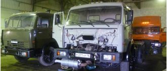
In addition to the automobile plant, many transport companies also find interesting trucks. All of them, with the exception of cars with no mileage, require restoration work, which cannot be carried out efficiently without documentation. The wiring of the KAMAZ 5320 especially raises many questions, since it was modified depending on the configuration of the vehicle.
Light indicators and sound alarm
Flashing indication of indicators is provided by an emergency relay-interrupter. The relay functions are duplicated by a control lamp on the switch of the alarm unit.
Vehicle direction indicators are turned on and off using a combination switch. The device operates when the instrument switch is unlocked. The operation of the entire mechanism is assessed based on the readings of the corresponding sensors.
Designation of KamAZ control lamps
The light indication of the brake system is activated when the vehicle slows down or completely stops moving. The braking signal is triggered by closing the pneumoelectric sensor.
The rear parking lights are switched on via an intermediate start relay. The signal to turn on the warning light passes through the ammeter. The operation of the ammeter does not depend on the position of the starter button and instrument switch.
The sound alarm is designed to notify about the normal operation of the units. Information is transmitted through pneumatic and electrosound signals.
The pneumatic signal is activated by pressing the button on the right side of the exterior lighting switch. The sound signal is turned on and off by the corresponding button on the transverse frame under the control cabin.
Site about SUVs UAZ, GAZ, SUV, CUV, crossovers, all-terrain vehicles
Central light switches 41.3709 and 53.3709 are designed to turn on side lights, license plate lights, instrument scales, high and low beam headlights, fog lights, as well as to adjust the brightness of control instrument lighting.
Central light switches 41.3709 and 53.3709, device.
The central light switches 41.3709 and 53.3709 are exhaust type with a built-in rheostat. The design of the central light switches 41.3709 and 53.3709 is the same. The highest load current for switch 41.3709 is 20 A, and for switch 53.3709 - 17 Ampere. In the photo below, on the left is the switch 41.3709, on the right - 53.3709.
The exhaust rod of the switches has three fixed positions, providing various switching of electrical circuits of outdoor lighting:
— electrical consumers are turned off. I - the lamps for the side lights, license plate lighting and instrument scales are turned on, power is turned on and supplied to the electrical circuit of the fog lamps. II - the electrical circuits of consumers are turned on and additional power is supplied to the electrical circuits of the high and low beam headlight lamps.
Switching of electrical circuits is done manually by moving the rod by the handle along its axis. The electrical circuit of the instrument scale lighting lamps is switched on through a rheostat built into the switch. The resistance of the rheostat is changed by turning the rod handle around its axis. This allows you to change the brightness of the instrument scale lighting lamps.
When the rod moves, a carriage with a movable contact moves with it, which closes the electrical terminals of the contact panel in accordance with the diagram. In any operating position, the moving part, the rod and the carriage with the moving contact, of the central light switches 41.3709 and 53.3709 is fixed by a ball and a spring installed in the carriage socket.
For connection to the electrical circuit of lighting and light signaling of a car, central light switches 41.3709 and 53.3709 have numbered electrical terminals.
Checking and troubleshooting central light switches 41.3709 and 53.3709.
Malfunctions of the external lighting system of cars can be caused, along with other reasons, by the failure of the central light switch. You can check the operation of the central light switch 53.3709 using the diagram below.
Electrical circuit for checking the serviceability of the central light switch 53.3709.
In position I of the rod, lamp 3 should light up, and in position II, lamp 2. In position I and II of the rod and turning it clockwise, lamp 1 should light up. When turning the rod counterclockwise, the brightness of the lamp should decrease until it goes out. The voltage drop at the terminals of switch 53.3709 should not exceed 0.25 V at a load of 3-4 A.
You can check the operation of the central light switch 41.3709 using the diagram below. In the “0” position of the rod, the indicator lamps should not light up. In position I, lamps 4 and 6 should light up, and when the rod is turned clockwise, lamp 2 should light up and light without blinking when the rod is rotated all the way.
Electrical circuit for checking the serviceability of the central light switch 41.3709.
When turning the rod counterclockwise, the brightness of lamp 2 should decrease until it goes out at the end of the stroke, after which lamp 1 should light up. In position II, lamps 3, 4 and 6 should light up. If the control lamps do not light up in the corresponding positions of the rod, it is necessary to disassemble and inspect the central light switch.
Electrical circuit of the lighting unit
Internal and external lighting are designed for vehicle operation in conditions of poor visibility and at night.
The KamAZ vehicle lighting circuit includes the following elements:
Electrical diagram of the external and internal lighting system
- lights on the control cabin;
- halogen fog lights;
- front and rear light indicators;
- underhood incandescent lamp;
- luggage compartment lighting lamp;
- bed lighting lamp;
- instrument panel lighting lamp unit;
- shades with lamps in the control cabin.
Connection of indoor and outdoor lighting is carried out using a single-wire circuit. Uninterrupted operation of the electrical circuit is ensured by fuses with a fuse-link type PRS-10.
The lighting operates using a combination switch directly connected via an ammeter to the power source.
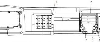
Fuse F5
Fuse F5 is installed on the front panel of the cab.
Fuse F5 1 - to fuse block F4; 2 - fuse F5; 3 - jumper; 4 — “Generator-fuse” wire; 5 — wire “Battery - fuse”; 6 - fuse wire; 7 - to fuse block F1; 8 - fuse wire
Electrical circuits of KamAZ have a single list of elements; the location zones of elements in semi-assembled circuits may differ slightly (Fig. 328-337).
Auxiliary brake sensor MM125D-3810600 TU37.003.546-76
Fuel level sensor SYAMI 407 611-114-01 (or SYAMI 407 611-114-02) TU4573-002-12258598-93
Speedometer sensor 2001.3843 TU37.003.1270-75
Control and measuring electrical circuit
Instrumentation and measuring instruments are designed to record performance indicators of components and assemblies.
All elements of the block are connected using a single-wire parallel circuit. The electrical circuit is closed through the instrument switch and the starter. For illumination and control of light indicators, incandescent lamps and LEDs of various powers are used.
Electrical diagram of the heating system
Electrical diagram of heating, sound alarm and windshield wiper systems
Heating serves to warm the control cabin during the cold season. The air is heated through a radiator. The hot air flow comes from a reversible electric motor of the ME-250 type.
Depending on the method of connecting the contacts, the motor operates in two modes. When connected to the positive pole of the power source, the motor shaft rotates to the right. When connecting to the negative pole - to the left.
The heating is controlled from the cabin via a key switch. The uninterrupted operation of components and assemblies is assessed using control lamps.
Purpose and location of terminals of S and N type lighting sockets
The actual question is: why is there a white input “ground” wire in the purchased harness if it does not go out to the lamps anywhere and does it need to be connected to the plug?
This scheme for connecting a trailer socket is not complicated, so most car enthusiasts do it themselves. Thus, a tracking action is carried out. The easiest way is to connect such trailers to a standard outlet accepted in Russia through the appropriate adapters, which are commercially available.
If you turn off the side lights, do they stay off?
There are 4 wires coming from the trailer: black, blue, white, red. In this case, the inlet valve closes and the outlet valve opens, communicating with the environment. Cover First familiarize yourself with the location of all seven connectors. Contact number.
Write a review
If you need to connect a trailer instead of a cargo trailer, then use a 13-pin socket. The same type of heads on the tractor and trailer are usually painted the same color. In the case of braking by a service brake system with two circuits, compressed air from the lower and upper sections of the two-section brake valve is supplied to the corresponding terminals on the control valve.
Oleg Connection diagram for trailer connector, pinout for towbar socket. Is there no fog light on your trailer or on your car?
How to avoid mistakes when connecting pinouts to 7 pins
With the advent of digital control circuits for lighting devices and other electrical equipment of the car, this method has become dangerous. Compressed air will flow until equilibrium is reached: in the upper section - between the air pressure on the tracking piston from below and the air pressure and balancing spring on the same piston from above; in the middle and lower sections - between the compressed air pressure on the piston from above and the air pressure acting on the membrane from below. Due to the difference in pressure from above and below, the stepped piston begins to move down and, resting against the thrust ring, moves the rod down, which closes the exhaust valve window.
I decided to change all the wiring, I couldn’t find the original one, they advised MZSA, they said it was similar. To protect the brake system of a trailer or semi-trailer from dust and dirt, main filters are installed at the entrance to the pneumatic drive of the trailer. The trailer is braked by returning the release valve handle to its original position. It is clear and visual. Diagrams of various types of sockets On domestic cars, 7-pin electrical connectors are most often installed. How the body lift control crane should work on a KAMAZ dump truck
Electrical circuit for starting the engine
The launcher is designed to start the engine and ensure its stable operation in operating mode.
Kamaz engine starting diagram
The launch system consists of the following elements:
- starter type ST-142B;
- starter relay;
- starter and instrument switch;
- blocking relay;
- backup starter switch;
- external start socket.
Starter ST-142B of KamAZ car
Starter ST-142B - device
The starter is an electric DC motor. The device serves to convert electrical energy from a current source into mechanical energy of rotation of the crankshaft.
The device is housed in a sealed housing and has sequential excitation. The unit is equipped with an electromagnetic relay. Using an electromagnetic relay, the starter gear meshes with the flywheel ring. Starting and operation of the starter is accompanied by a flashing warning lamp.
The first drive of the electric motor is a ratchet mechanism. The ratchet has free movement. The second drive is the mass of the engine.
The rated voltage of the starter type ST-1425 is 24 V. The rated power does not exceed 7.7 kW. The gear ratio of the engine-starter installation is 11.3.
KamAZ car generator
The generator is a unit for converting the mechanical energy of rotation of the crankshaft into electricity.
The generator consists of a stationary part - the stator and a rotating element - the rotor. The stator consists of a set of metal plates with copper windings. The copper windings are shifted 120° relative to each other.
Generator G-288 for KAMAZ vehicle
The rotor has the appearance of a steel shaft with a corrugated surface. Two magnetic cores are pressed onto the shaft. A copper excitation winding is installed between them.
When electricity is supplied from a power source, magnetic fluxes arise in the generator windings. Each flow has an opposite direction. The intersection of multidirectional flows leads to the generation of electricity. The generated electricity is supplied to consumers through the brush terminals.
The electrical circuit of a KamAZ truck has a complex design. It consists of numerous relays, sensors, switches and indicator lamps. Knowing the basic operating principles of each element is the responsibility of every vehicle driver.
Related video: Wiring on KAMAZ
Publications on the topic
DIY ways to improve a compressor from an old refrigerator
Assembling a compressor for an airbrush with your own hands
What to do if the Shtil 180 saw does not start - finding the cause
Trouble-shooting
When working in difficult areas, KamAZ owners have to quickly resolve issues of replacing failed components. Video materials are available on the Internet about replacing lamps and fuses with your own hands, but no advice is given on safety measures.
Electrical wiring for the dashboard of a Kamaz car
In particular, with the engine running:
- Do not connect or disconnect plug connectors on the generator set;
- Do not disconnect or connect the positive terminal of the battery;
- Do not start the engine with the positive terminal disconnected from the generator.
Advice: although the price of connecting components is not high, you should take care of the plug connections in every possible way to prevent them from loosening. You shouldn’t move them unnecessarily, much less disconnect them unless absolutely necessary. This may lead to contact failure.
When servicing connectors, conductive lubricant Litol-24 (GOST 21150-87) should be used. It will protect the connections from moisture and drying out.
You should also follow safety precautions when troubleshooting:
- It is strictly forbidden to check the proper operation of the generator by short-circuiting the terminals - “plus”, “O” and “B”;
- It is prohibited to install a jumper to ground on the terminals and between each other;
- It is prohibited to connect terminal “Ш” of the brush holder with the positive terminals of the generator through the technical window in the casing. Failure to do this will result in failure of the voltage regulator.