Gearbox UAZ 469. device, repair and photo
Article navigation
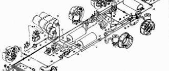
Connection diagram
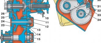
Shaft 11 rotates in a roller bearing, which is installed in the housing cover of the UAZ 469 wheel reducer, and in a bronze bushing inside axle 18. At the end of shaft 11 there is a mechanism for disconnecting the front wheels of the vehicle. The device consists of movable rods 14 and 15, which are located on the splines of the shaft and bolts 17 and 16 with a spring and a ball.
These movable couplings are connected by their external splines to the internal splines of the drive flanges 13 and 14, which are bolted to the wheel hubs. To reduce wear on the metal surfaces of the front axle parts of the UAZ 469 and save fuel when driving on paved roads, it is recommended to disconnect the front wheel hubs at the same time as disconnecting the front drive axle.
To perform this disconnection, remove the protective caps 16 and 18. Then unscrew the screws 16 and 17 from the hole in the shaft 11. Place the coupling in such a position that the groove of the signal ring “a” on its plane is in the same plane with the end of the flange. When the coupling is installed in the required position, tighten the protective caps.
The wheels must be secured by screwing in bolts 16 and 17. The bolts must be tightly tightened. Disabling and enabling must be done simultaneously on two wheels of the front drive axle. DO NOT engage the front axle with the wheels disabled!
What are the options for diff locks for UAZ - a brief overview and cost
The most common differential locking schemes for UAZ Patriot:
- A self-locking mechanism (when disabled), developed by Val Racing for installation on axles with a “spicer” design. For activation, a power pneumatic drive is used, powered by a separate electric compressor (not included in the kit). The cost of the set intended for the front axle is 22.3 thousand rubles. A set of parts for the rear axle drive will cost another 22.3 thousand rubles; in addition, you need to buy a pump and air lines.
- The product of the Sprut company is intended for installation on bridges of the “spicer” circuit. Control is carried out by compressed air, which is pumped by a compressor. Additionally, gas supplied to the gearbox housings prevents the ingress of water, which causes leaching of lubricant and corrosion of gears. The cost of parts for 1 bridge is 22 thousand rubles, the set includes an electronic air distributor powered by the vehicle’s on-board network.
- The electric locking drive is supplied by Eaton; there are versions with a transfer case control unit. The design of the unit does not require maintenance during operation; when the lock is turned off, the differential operates as a standard unit. The blocker is driven by an electrically driven magnet; the control button is located on the instrument panel or center console. The cost of the set starts from 41 thousand rubles, the use of reinforced axle shafts is recommended.
- A mechanical drive from the Nirfi company will cost the buyer 20.4 thousand rubles. (per set for 1 bridge). The design is reliable because it consists of a rod and a shift lever located inside the car. To install the device, you need to cut a hole in the axle housing, which makes it difficult to install the lock yourself. Used differential housings are used to make the kits.
- Screw blocker supplied by Val Racing. The device costs about 20 thousand rubles, and turns on automatically when the load on the transmission increases. The DAK self-locking unit (Krasnikov’s design), which uses screws and balls, has a similar design. Under standard motion conditions, the balls move freely; when slippage is detected, the device automatically locks. After equalizing the rotation speeds of the wheels, the block is removed.
- A homemade design in which the opposite teeth of a gear (at 90°) located on the axle shaft are welded. The use of such a device worsens the controllability of the machine and increases the load on the transmission. The cost of such a design is minimal, but the consequences of use will exceed the price of factory devices.
Differences between military bridges and civilian ones
Military and civilian bridges differ in that the former have not only a main gear, but also final wheel drives. The transfer case design of these cars is identical. The transmission of the UAZ 469 increases the torque received by each wheel, so a vehicle with a military axle has much better off-road and on-road characteristics.
A significant advantage of this system is that the axle of a military vehicle with side gears is 4 cm higher than that of a civilian vehicle. As a result, the vehicle's ground clearance is significantly improved when overcoming obstacles on the road. At the same time, military axles are manufactured with an overall gear ratio that is much higher than all other designs. This results in a significant increase in torque. A car with such characteristics is slightly inferior to its analogues in terms of speed characteristics.
An engine that constantly operates at high crankshaft speeds wears out its life much faster. The gear ratio of old civil bridges is 4.625 or 5.125. This depends on the number of teeth on the final drive sprocket.
For Military axles, the gear ratio is 5.38. The final drive ratio is 2.77 and the final drive ratio is 1.94. For Spicer axles, the gear ratio is 4.111. This is for carburetor cars. The gear ratio for diesel cars is 4.625.
On civilian UAZ 469 axles, a differential with forced or automatic locking is installed on each axle. The locking drive is used in different ways:
- pneumatic;
- Electricity;
- mechanical.
When installing a pneumatic drive, the car is retrofitted with a pneumatic system of the simplest design. In addition to blocking the UAZ 469 on civilian axles, it can solve many related problems.
Different bridges in the UAZ 469 differ in track width. Civilian and military axles were once produced in widths of 1443-1445 mm. Now the plant produces blocks up to 1600 mm wide. This is basically a modern Spicer design. The axial weight of the UAZ 469 collective farm is 120 kg, military 140 kg.
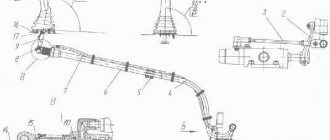
Construction of a military bridge (photo)
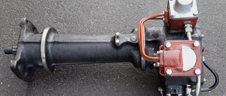
UAZ steering axle boot
Photo of an open side gearbox of a military UAZ axle
Image of a dismantled onboard gearbox of a UAZ car
Military bridge UAZ mushroom
Repair Gearbox UAZ 469
Assembling a pump for an IZH-Techno fire truck on a military axle
Dismantling the differential bearing of the UAZ military axle
Video replacement and adjustment of the main pair on the UAZ military bridge
What is forced differential locking?
UAZ off-road vehicles are equipped with a 2-axle drive, which includes a center differential. The driver will not be able to engage the drive on all tires without first blocking the mechanism. Additional factory differentials are installed in the axle housings, distributing torque between the tires on the left and right sides of the car. If one of the wheels hits soft ground, the opposite tire stops rotating, which makes it difficult to independently free the vehicle from the mud.
To increase cross-country ability, the UAZ differential lock is used, located in the front or rear axle. The differential design uses 2 bevel gears mounted on axle shafts. There are 4 satellites between the gear wheels, the entire structure is mounted on bearing supports in a steel housing, which is located in the axle housing.
For forced locking, it is necessary to stop the rotation of the satellites, ensuring direct transmission of torque to the axle shaft.
Types of differential lock drives:
- mechanical, performed by a lever and a rod (or cable);
- hydraulic or pneumatic, the design of the blocker includes a power cylinder, which is acted upon by liquid or compressed gas;
- electric, the position of the working elements is changed by an electromagnet or an electric motor.
Blocker drive.
Read: why install hubs on UAZ?
Rear axle structure of UAZ 469
The design of this device
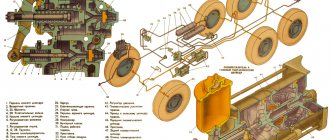
The Soviet SUV UAZ 469, produced by the Ulyanovsk Automobile Plant, is unique in its own way. The diagram of the rear axle of the car is shown in Fig. 1. The design includes the following main components and assemblies:
- 1 — protective tab;
- 2 — differential roller bearing;
- 3, 8 — self-correcting pads;
- 4 — rear end of the gear bracket;
- 5 — correction ring;
- 6 — handle of the oil dispensing column;
- 7 - nut;
- 9 — front strut of the rear axle;
- 10 — head bearing bracket;
- 11 — thrust washer of the hydraulic sprocket axle shaft;
- 12 - gear element.
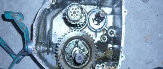
Features of unit dismantling
When removing the rear axle, unscrew the rear nut, remove the washer, mating flange, front pinion shaft assembly cover, and press the pinion shaft assembly and bearings out of the rear oil cooler.
This diagram is ideal for removing the differential gear. The next step is to unscrew the splines of the connection between the planetary gear and the pinion gear and reset it. Separate the two parts of the box, remove the gears, planetary gear rods, and support nuts. When assessing disassembly, pay attention to the integrity of the gear teeth. If they are damaged, replace them. Special tools are required to remove the rollers, outer and inner rings. Carefully study and understand the disassembly sequence so that when reassembling you can accurately perform all steps in reverse order.
When inspecting the oil scraper ring, check for any irregularities on the surface. If yes, sand to 5mm thickness. The same applies to the universal joint flange. Grind to a height of 53 mm. Clean the housing surfaces. Blow out the oil bushings. Replace drive structure parts and half shafts if burred or severely worn.
Gearbox UAZ 469.Adjustment
Before adjusting, prepare everything you need: bushings in the hinge (if the hinge is worn), 4 thrust bushings and oil seals. The main prerequisite for adjustment is that both halves of the joint do not sag, both during straight-line movement and during rotation! The procedure is performed as follows:
- Take the ball bearing and press the bushing into it so that half of the joint does not hang in the ball bearing.
- There is a thrust washer on top, be sure to install a new one even if the old one looks in good condition.
- Take a metal shaft (it can be made, for example, from a valve) with cones on both sides and insert a washer of the same diameter as the central ball, i.e. 27 mm. Place one edge against the center of the kingpin. Ideally, the other end should also be aligned with the kingpin. If not, install the washers in the same place as the kingpin, or preferably under it. Adjustment
- The knuckle body should be mounted on top of the ball bearing, and the center of the large hole in the knuckle should be aligned with the center of the bearing. If it's off by even 3mm, you won't be able to install the ball joint because the bushing is already there. To center, place a certain number of shims under the left or right knuckle pin, depending on which side and by how many mm you want to shift the central axis.
- The journals must be tightened so that the ball joint can be rotated back and forth by hand. If the trunnion seat is cracked and the trunnion rotates with the ball joint, grind a few millimeters on the trunnion and thread it through the bushing. Do not twist or loosen as this will cause premature wear of the pin and socket.
- It is better to replace the bushing in the hinge itself (both front and rear). If necessary, adjust the size using a reamer. It is important to remember that this needs to be done differently for each half of the domino. There shouldn't be any slack, but if one half of the joint is too tight, it's best to remove more with a reamer.
- It is very important that the bushings are located in the locations shown in the figure. If you place the bushing on only one side, then when the wheel turns, most of the load will fall on it, resulting in rapid wear, the appearance of play, and then the ball needs to be replaced. Install bronze bushings at these points
When assembling the UAZ 469 gearbox after repair, it is necessary to lubricate all the nitro bolts so that next time it will be easier to unscrew them. All mounting surfaces (the joint between the joint and the steering knuckle housing) must be free of dirt. It is not recommended to lubricate the crankshaft with grease, as it is thick. When heated under the action of centrifugal force, all the grease is dispersed on the walls of the ball bearing, so it is necessary to lubricate the balls in the hinge. To do this, it is recommended to dilute solid oil by half with nigella.
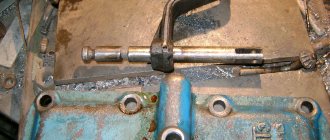
After final assembly and repair, one more important adjustment must be made. We are talking about an adjusting rotary bolt. This is a screw that limits the maximum angle of rotation of the wheel. It is important not to tighten the bolt all the way, otherwise the wheel will jam. Tighten almost all the way, and then try to turn the wheel (or rather, the shaft on which it will sit). Turn the bolt in the opposite direction until the wheel stops sticking. The angle of rotation should not be less than the factory one. Now you can repair the front axle in 469 UAZ yourself!
Source
Installation and configuration
Algorithm for installing differential lock on UAZ Patriot cars:
- The car is placed on a lift or inspection pit.
- Remove the tires and rims located on the front or rear axle, and then remove the brakes.
- Remove the drive axle shafts from the crankcases, and then disconnect the driveshaft going from the transfer case to the axle gearbox.
- Drain the oil from the crankcase through the standard hole located in the lower part of the housing.
- Unscrew the bolts securing the main pair and the differential mechanism. Then the devices are removed from the crankcase cavity; it is recommended to check the condition of the tapered bearings. If wear or play is detected, parts must be replaced. To replace the bearings, a special puller is used; installation is carried out using metal mandrels corresponding to the diameters of the rings.
- Install the modified unit in its original place, and then mount the parts in place. During installation, it is necessary to observe the tightening torques of threaded connections recommended by the manufacturer. Gaskets must be replaced; if old seals are used, oil may leak through the joints.
- Setting up the locker is not required; the gears of the main pair are adjusted to ensure the contact patch between the teeth. To change the position of the gears, washers are used, which are selected depending on the transmission parameters (markings are applied to the end part of the gears).
- Fill the gearboxes with oil; the type and volume of lubricant are indicated in the documentation supplied by the factory to the UAZ Patriot vehicle.
- If a pneumatically driven lock is used, the compressor and receiver are located in the luggage compartment. The pump motor is connected to the on-board network via a fuse, and control buttons are installed in the cabin.
- After connecting the lines and installing the distributor, the functionality of the locking mechanism is checked.
UAZ rear axle
This article describes and illustrates the rear axle of the UAZ. Here you can find information about all of its models. UAZ vehicles are equipped with rear axles Timken, Spicer and a military axle (axle with final drive). This page provides information about their design. All the parts that make up these UAZ rear axle models are described and shown in detail.
The following types of rear axles are installed on UAZ vehicles:
- 1 - Timken: Main gear ratio - 4.625.
- Final drive ratio - 4.375 or 4.111
- Main gear ratio - 2.77;
Types of locks
If something happens to such a design or the differential begins to work incorrectly, it is better to repair the part. And since the mechanism is located in the gearbox, to remove it it is necessary to remove the entire assembly.
The first thing to do is to remove the side gears by turning them around the pinions. To be able to remove the satellites, it is necessary to remove the retaining ring from their axis. Then the driven gear should be released, for which the bolts in the differential mount must be unscrewed. The entire part is disconnected from the body using a chisel and hammer.
Disassembling the unit
All detached parts may have minor defects, which can be easily removed using fine-grained sandpaper. If they cannot be corrected manually, it is better to put the differential up for sale and purchase a new one. The normal operation of the differential may be hampered by a defect on the driven gear in the gearbox. It is advisable to replace this part to prevent further damage to the entire assembly.
Bearings can quickly become unusable and are best replaced immediately. The differential housing itself is replaced if the bearing seats are quite worn.
Rear axle UAZ Patriot Spicer type
View of the Spicer rear axle
Rear axle structure of the UAZ Patriot
Rear axle gearbox UAZ Patriot
* — One of the rings is installed according to your choice
**- The set consists of:
- 3160-2403019 — Left differential box assembly;
- 3741-2403018 — Right differential box cup assembly.
*** — The set consists of:
- 452-2403050-01 — Axle shaft gear;
- 452-2403055 - Satellite.