At each facility, from work performed on the territory of the construction site, there must be a fencing of the boundary of the danger zone to protect the working personnel and people not involved in the work from hazardous factors. Depending on the presence or absence of lifting structures (cranes, hoists, pipe layers, etc.), working machines and mechanisms (excavator, dump truck, pile driver, vibratory loader, concrete pump, asphalt paver, roller, bulldozer, etc.), the height of the building under construction and/ or the depths of the excavated soils, the following boundaries of the danger zone are distinguished:
- from the height of the fall of materials, equipment, tools and other objects and their departure;
- from moving parts of machines and mechanisms;
- from cargo moved by a crane, loader crane, pipe layer or other subs and its flight;
- from the tests carried out (hydraulic, pneumatic tests of pipelines);
- to height differences (trenches, pits, floors of buildings).
Boundary of the danger zone from falling objects from buildings and structures
Near a building under construction, the boundary of the danger zone is designated in the form of a permanent fence (when performing construction, installation and dismantling work in urban areas) or temporary fencing (at an existing enterprise when short-term work is carried out, when constructing an object on an empty site). Mandatory during construction. near buildings and structures under construction, it is necessary to reflect in the PPR the boundary of the danger zone from the fall of objects, materials, and structures from them. In accordance with the requirements of SNiP 12-03-2001, it is determined by the distance of the object (load, structure, etc.) from the wall of a building or structure - X (shown in the figure below) plus the maximum overall size of the object - Lload.
Definition of the concept
Sites near:
- buildings under construction;
- operation of cranes, pipe layers;
- operation of excavators, dump trucks, asphalt pavers and other machines;
- pipeline testing;
- sudden changes in height - pits, trenches.
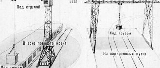
Danger zones when operating a jib crane
The perimeters of each area are designated separately, depending on the type of equipment being operated and the potential hazard factor.
Boundary of the danger zone from the operation of lifts and towers
The same principle applies to lifts and towers in which loads and tools are moved to heights. In this case, the distance to the boundary of the danger zone is taken from the edge of the cradle, the lift platform, but is taken to be at least 5 m, since the distance from operating mechanisms is taken to be at least 5 m.
First, in the PPR for the operation of lifts, the working radius of rotation of the cradle necessary for the work is determined, and then the calculated distance Ro.z is set aside from it. For towers and construction hoists that are stationary, this distance is taken from their edge and described around it. All calculated boundaries of the OZ are transferred to the work site after installation of the substation. To avoid errors, the fencing of the danger zone must be installed at a short distance from Ro.z.
The height of a possible fall of an object (load) is taken from the installation site of a lift, tower to the top of the cradle railing or platform, and when installing any equipment - to its bottom.
Formula for calculating boundaries
The most convenient formula for calculating the area of a plot looks like this:
Rcr (o. z.) = P (max) st. + 0.5 * R (min) gr. + P (exc) + P (max) gr.
Legend:
- Rkr (o.z.) – radius of the dangerous section;
- R (max) st. – maximum boom reach;
- R (min) gr. – minimum dimensions of building materials;
- P (ex) – distance of departure of the fallen load;
- P (max) gr. – maximum length of the load.
The boundary of the danger zone when operating a crane, pipe layer, etc.
When carrying out work using lifting structures (cranes, pipe layers, manipulator cranes, etc.), there is a danger from falling loads during their movement. From the axis of the transported load (hook) during work, the boundary of the dangerous zone is established, determined by the following formula:
Ro.z. = Lload + Bload/2 + X, where:
- Lload and Bload - horizontal projection of the minimum size of the load when moving its PS;
- Lcargo and Bcargo - the maximum size of the cargo when moving it by the PS;
- X is the minimum departure distance of the transported cargo, determined in accordance with the table:
| Height of possible drop of load, m (H) | Minimum distance of departure of the transported (falling) load in case of its fall when moving the PS, m (X) |
| To 10 | 4 |
| Up to 20 | 7 |
| Up to 70 | 10 |
| Up to 120 | 15 |
| Up to 200 | 20 |
| Up to 300 | 25 |
| Up to 450 | 30 |
Note. For intermediate values, distance X is determined by interpolation using the formula:
X = X1+(X2-X1)*(H-H1)/(H2-H1), where: — X1 is the previous value of the load departure; — X2 is the next value of the cargo departure; — H—required height for calculation; — H1 — previous value of the height of the transported load; — H2 — the next value of the height of the transported load. For example, when moving a load at a height of H = 14 m, the take-off distance will be: X = 4+(7-4)*(14-10)/(20-10) = 5.2 m.
Place of work of equipment
Crane danger zone
The danger zone around a truck crane is the distance where loads are moved. This includes the loading location from the crane, as well as the distance over which the dropped load (slab) can fly off. Therefore, the boundaries are calculated using a special formula, which takes into account the dimensions of building materials, the dimensions of the machine and the safety area.
The crane's service area depends on the maximum reach of its boom. It is designated as P (max). To determine the distance at which fallen building material can fly off (P (ex)), you need to know the height of its rise. The height is calculated from the surface of the construction site to the bottom of the suspended slab.
Boundary of the danger zone near moving machines and mechanisms
At the construction site, the boundary of the dangerous zone is allocated from the equipment, machines and mechanisms involved, equal to 5 m from the moving working parts of the equipment of machines and mechanisms (clause G.4 SNiP 12-03-2001). Other increasing requirements may be specified in the operating manual or passport. This boundary can be located both inside and outside the boundary of the departure of an object, cargo from a building, during the operation of cranes, lifts, etc.
Designation of a construction site
After calculating the risky section, you need to think about how to protect it from builders. The performance of builders depends on correct calculations and reliable fencing. Potentially hazardous areas at a construction site should be separated by signal barriers with safety signs.
Fences and signs must comply with GOST standards. They should be clearly visible from all sides, and backlighting is necessary in the dark. Special signs must hang on stands that are securely fastened so that they do not fall on people or equipment. It is forbidden to place cabins for resting workers, sanitary facilities, or passages for people on a temporary construction site.
How to limit the boundary of the danger zone?
At a construction site in cramped conditions, it is possible to limit the boundary of the danger zone from emerging hazardous factors by limiting the operation of machines and mechanisms, installing additional fences, etc.:
- When placing jib and tower cranes, manipulator cranes, it is necessary to forcibly limit the angle of rotation of the crane boom by installing boom rotation limiters.
- When working at height from scaffolding, at the upper levels of buildings and structures, install protective nets and additional fences that prevent cargo, tools and other objects from flying off beyond its boundaries.
Stroygenplan
A construction plan is a drawing of a construction site, which shows:
- building under construction or renovation;
- warehouses - see the count;
- fencing the site and communications;
- roads;
- arrangement of mechanisms;
- household premises.
The location of the mechanisms and the placement of warehouses on the site changes periodically as the work progresses. Thus, the construction plan should reflect the location of the main elements as accurately as possible. In addition, it is possible to place soil dumps at the site. This document is drawn up in addition to the house construction project and serves to organize the builders.
During the construction of the building box, a tower crane will operate on site and a significant part of the territory will be allocated for storage areas for prefabricated parts. During finishing work, there may not be a tower crane on site and the area of storage areas will be sharply reduced, so construction plans are often drawn up for different stages of construction.
To successfully design a construction plan you must:
Stroygenplan and roads
When placing roads on a site, they strive to provide a circular bypass around a building under construction or renovation with the arrangement of three entrances and exits from the site. The traffic will be one-way.
If the site conditions do not allow for a roundabout, then they are limited to a road on one side of the building with two entrances and exits, but unloading areas must be provided or the entire road must be designed for two-way traffic.
The section of the road on which the vehicles will be located during unloading must be within the range of the installation crane. Roads must be placed on the site in such a way that cargo flows do not interfere with the movement of workers.
Placement of warehouses on the construction plan
Storage areas for precast concrete parts are located between the installation crane and the road. In addition, with jib cranes, the platforms are placed on the side opposite the main passage, so that each crane station has a storage area. During repairs, if a tower-type lift is installed at the facility, storage areas are arranged in the lift’s coverage area.
If another type of lift is installed, storage areas are organized to the side, but a mechanism is provided for supplying materials from the warehouse to the lift area (forklift or truck crane).
Sheds are placed near roads in such a way that part of the canopy is within the crane’s range of action, and part is outside it. Closed warehouses are located outside the range of the erection crane.
Stroygenplan and warehouses
When carrying out zero-cycle work, the construction plan must show the roads that ensure the removal of soil during excavation, the placement of soil dumps and storage areas for storing prefabricated parts. The placement of roads for soil removal depends on the type of excavator and the type of excavation.
Introducing restrictions on the operation of cranes
When operating assembly cranes in cramped conditions, it becomes necessary to limit the movement of the crane: turning the boom, changing the reach of the boom, moving the crane or cargo trolley.
Forced restrictions
are carried out by installing appropriate sensors and limit switches that perform an emergency shutdown of the crane within specified limits, and do not depend on the actions of the crane operator.
Conditional limits are fully calculated on the attention and experience of the crane operator, slinger and assembler. Symbols are shown on the ground with clearly visible signals: during the day - with red flags, and at night - with red garlands of lamps or lanterns, which warn the crane operator about approaching the border of the prohibited sector. The placement of signals indicating the method of their execution is indicated on the construction plan.
To ensure compliance with conditional restrictions, instructions on the procedure for carrying out work are developed in each specific case. When calculating boom rotation limits, the braking distance of the boom must be taken into account. To do this, the limiters are installed so that the boom rotation is turned off 2..3 degrees earlier than the established norm.
The joint operation of several mechanisms in one zone is, as a rule, prohibited. In case of production necessity, joint operation of an assembly crane with other construction machines and mechanisms, including other cranes, may be permitted subject to the development of special measures to ensure safe conditions. Another mechanism should be working in the next zone at this time.
9.3. Construction Site Zones
When operating a crane on building construction, the following dangerous areas for people can be identified:
a) installation area - a space where a load can fall when installing and securing elements. The area of this zone is determined by the contour of the building with the addition of 7 m for a building height of up to 20 m, 10 m for a height of more than 20 m. Only assembly mechanisms may be placed in the installation area; storing materials here is prohibited;
b) the service area of the crane or the working area of the crane, determined by the radius of the maximum working reach of the crane boom in the area between the extreme crane stops on the rail track or traffic lane;
c) cargo movement zone (P) - a place where cargo can fall during movement. For most cranes, the zone boundary is determined by a radius equal to the sum of the maximum working reach of the hook and 0.5 of the length of the longest one being moved;
d) a dangerous area for people to be in during the period of lifting, installing and securing loads. The boundaries of the zone are determined taking into account the likely dispersion due to a possible drop of the load.
e) dangerous zone of crane tracks - a fenced area of crane tracks. The minimum distance from the rail to the fence is taken to be 0.7 m;
f) the dangerous zone of operation of the lift is taken to be at least 5 m from the overall dimensions of the lift, and when lifting to a greater height, 1 m is added for every 15 m of rise;
g) dangerous zone of the road - sections of roads, entrances and approaches within the listed zones where people who are not involved in working with the crane, vehicles and other mechanisms may be located;
h) the dangerous zone of installation of structures, indicated when the crane is tied vertically. They appear during the installation of structures on the upper floors of the building. The presence of dangerous zones in the installation of structures requires the development of special measures (issuing work orders for particularly dangerous installation work, fencing off zones with visible signals, etc.).
When working in cramped, difficult or particularly difficult conditions, some crane movements must be limited. Such work may include:
— construction of a building in dense urban areas or an operating enterprise;
— reconstruction of an industrial workshop, residential or public building;
— construction of wide-frame buildings using the “self-assisted” method;
— joint work of 2-3 cranes or a crane and a construction hoist;
— work in the security zone of power lines, above existing underground utilities, in places where vehicles and pedestrians move, etc.
The dangerous zone of crane operation is the space where a load can fall during its movement, taking into account the likely dispersion when falling.
The boundary of the dangerous zone of the crane is determined by the radius, which is calculated by the formula:
R = Rmax + 0.5 lmax + l without, m
where Rmax
– maximum working radius of the crane boom, m;
0.5lmax
– half of the largest overall size of the transported cargo, m;
without
— additional distance for safe work, established by DBN “Occupational Safety and Health in Construction” /2/.
The danger zone of a lift is the space where the load being lifted can fall. The zone should be at least 5 m from the dimensions of the lift in plan, and when lifting to a greater height, 1 m should be added for every 15 m of lift.
Dangerous zones on the construction plan are indicated by a dash-dotted line. At the boundaries of the zones, it is necessary to install appropriate warning signs.
Passage areas for people in hazardous areas
must have protective barriers. Entrances to buildings (structures) under construction must be protected from above by a canopy at least 2 m wide from the building wall. The angle formed by the canopy and the overlying wall above the entrance, i.e. The angle of inclination of the visor should be 70...75°.
Wells, pits and other excavations in the ground in places where people can access must be covered with covers, strong shields or fenced. At night, the fence must be marked with electric warning lamps with a voltage not exceeding 42 V.
9.4. Organization of cargo transportation
9.4.1. Construction materials
During the construction of any building or structure, certain transport and loading and unloading operations are performed related to the delivery of materials, semi-finished products and products from the production sites to the construction site. Delivery of these materials is a complex process involving loading, transportation, unloading and warehousing. In the cost of some building materials, transportation costs sometimes exceed extraction or manufacturing costs.
The elements delivered for the construction of a structure are called construction loads, which are classified according to their physical and geometric characteristics into 9 types:
— · bulk
– sand, crushed stone, gravel, soil, construction waste;
— · powdery
– cement, lime, gypsum, chalk;
— · pasty
– concrete mixture, mortar, lime paste;
— · small-piece
– brick, small blocks, rubble stone, asphalt tiles, paint cans, loads in boxes and bags;
— · piece
– window and door blocks, reinforced concrete panels and slabs;
— · long
– reinforced concrete and steel columns, trusses, pipes, timber;
— · large-volume
– sanitary cabins, block rooms, blocks of elevator shafts, large containers;
— · liquid
– gasoline, kerosene, lubricants;
— · heavy
– reinforced concrete elements of significant mass, technological equipment, construction machines delivered to the construction site by vehicles.
The configuration places special demands on the methods of delivering materials and structures to the work area, which for the most part must be load-free. This principle is best met by methods of packaging and containerization of construction materials.
Plastic bag
– this is an enlarged cargo (cargo package), formed from a certain number of small elements and fastened in such a way as to ensure the unchanged shape of the package. The package can be formed on or without a pallet using various methods of securing loads. Packages are used when delivering small-piece materials (bricks, blocks, window blocks, doors, etc.), as well as rolled metal, fittings, and lumber to a construction site.
A container is an inventory container in the form of a three-dimensional spatial structure intended for the transportation and short-term storage of small-piece and expensive cargo.
With containerization and packaging, the cost of manual labor during loading and unloading operations for both suppliers and consumers is sharply reduced, conditions are created for widespread mechanization of work, vehicle downtime is sharply reduced, the need for freight forwarding is eliminated, and the likelihood of damage and losses during transportation is reduced.
According to their purpose, containers are divided into universal and special ones.
Universal containers are a voluminous covered body that is installed on the vehicle platform for the period of transportation. Such containers are designed for transportation of various cargoes.
Special containers are used to transport one or more cargo of similar properties. Some specialized vehicles are essentially special containers (bitumen tankers, cement tankers, mixers, trailers designed for transporting panels, partitions, beams, trusses, etc.).
9.4.2. Transportation of goods
In relation to the construction site, transport is divided into external (external transportation) and object (internal transportation).
External transportation is the movement of construction cargo from manufacturing plants to the construction site.
Internal transportation is the movement of materials around the construction site from storage sites to places of laying in the design position.
To organize external transportation, depending on specific conditions, almost all types of transport are used. Motor transport is mainly used to organize internal transportation.
In modern conditions, motor transport is the most preferable, as it has mobility, maneuverability, and provides the ability to deliver building materials directly to storage areas on the construction site and lay them in the designed position.
Types of road transport used in construction
The choice of vehicles for transporting construction goods depends, first of all, on the nature of the goods being transported, as well as on the methods of containerization and packaging, the possibility of attracting appropriate vehicles and other conditions.
In general, the following types of vehicles are used for transportation:
- universal;
- specialized.
Universal vehicles include all types of on-board vehicles, automobile semi-trailers, trailers, and dump trucks.
Specialized vehicles include vehicles designed to transport only certain construction cargo: cement trucks, concrete and mortar trucks, panel trucks, truss trucks, column trucks, etc.
It is advisable to use road transport when delivering all cargo over distances of up to 200 km.
Tractor transport
used to move mainly heavy loads on bad roads and in off-road conditions. Disadvantages - limited possibility of use in urban environments and over significant transportation distances due to low travel speeds.
Railway transport
is mainly an external transport for long distance transportation. Rail transport requires large initial costs, but when the main cargo arrives along rail tracks, these costs quickly pay off during operation. Rail transport is rational for heavy loads and equipment, and for the concentrated construction of large facilities.
Water transport
– the cheapest type of transport, especially when transporting over long distances. One of the main disadvantages is the seasonality of use. River transport is convenient for use during concentrated construction in areas directly adjacent to river waters and with special port equipment.
Air Transport
used for delivery of goods to hard-to-reach places, as well as for transportation and installation of individual unique structures.
Special transport
– aerial cableways, pipeline transport, pneumatic transport, hydraulic transport, transport using link belt conveyors. These types of transport are used mainly in very rough terrain and in the presence of water obstacles.
Special types of transport include vehicles for technological purposes
, which combine transportation processes with technological processing of this construction cargo. Such vehicles include concrete mixer trucks, which simultaneously carry out the processes of preparing and transporting a concrete mixture to a construction site, concrete pump trucks, which combine transportation of the mixture over a considerable distance and its placement, and concrete trucks, which move and mix the mixture. Technological vehicles are promising and already play a significant role in modern construction.
Arranging delivery
various construction loads can be carried according to
several basic schemes
.
With a pendulum scheme
motor vehicles - a dump truck, a flatbed vehicle, a tractor with an uncoupled cargo trailer - stand idle for a certain time while loading and unloading this cargo. The pendulum scheme of road transport is effective in the presence of on-site warehouses or in the concentrated construction of structures from the same type of structural elements. In this case, specialized road trains are involved in the transport cycle, when a separate train or a group of road trains transports products of a certain range with their unloading in parts from facilities of the same type under construction.
Shuttle scheme
characterize significantly less vehicle downtime. With the help of a tractor, a trailer with a load is brought to the construction site, they uncouple it, attach a free one, return with it to the loading site at the plant, uncouple the trailer, leaving it for loading, attach the previously loaded trailer and take it to its destination. Three trailers are actually attached to the vehicle - one is being unloaded, the other is being loaded, and the third is being transported at this time.
9.4.3. Loading and unloading construction materials
Transportation of construction materials includes loading at the point of departure and unloading at the point of arrival.
For loading and unloading operations the following are used:
— mechanisms operating independently of vehicles;
— mechanisms that are part of the design of vehicles.
The first group of mechanisms includes all types of cranes, cyclic and continuous loaders, mobile belt conveyors, pneumatic unloaders, etc. The second group includes dump trucks, vehicles with self-unloading platforms, autonomous means for self-unloading, etc.
Vertical
The transport is designed to perform loading work at factories that supply building structures, unloading work when accepting materials and products received at a construction site, and when transporting goods vertically to the work site.
Horizontal
By transport, construction cargo is transported from the place of receipt to construction sites and directly at the sites themselves, if not a separate building is being erected, but an entire construction complex.
9.5. Design of temporary roads
To ensure the safe movement of goods and people around the construction site, access and on-site roads, pedestrian paths and sidewalks must be provided for when designing the construction master plan.
Temporary roads are constructed simultaneously with that part of the permanent ones intended for construction vehicles.
The design of roads as part of the SGP is carried out in a certain sequence:
1) development of traffic patterns and the location of roads in the plan;
2) determination of road parameters;
3) establishment of dangerous zones;
4) determination of additional conditions;
5) purpose of road structures;
6) calculation of the volume of work and required resources.
The traffic pattern and layout of roads in the plan should provide access to the area of operation of installation and loading and unloading mechanisms, to means of vertical transport, large assembly sites, warehouses, workshops, mechanized installations, household premises, etc. When developing a vehicle traffic pattern, existing and planned roads should be used as much as possible, and areas for passing and turning around should be constructed at dead-end entrances.
Construction sites and fenced areas within the site must have at least two entrances.
Near the entrance to the production area, it is necessary to establish a diagram of on-site roads and driveways indicating places for storing materials and structures, turning vehicles, fire water supply facilities, etc.
The SGP must clearly mark with appropriate symbols and inscriptions the entrances (exits) of transport, the direction of movement, turns, sidings, parking during unloading, reference dimensions, and also indicate the installation locations of signs that ensure the rational and safe use of transport. All elements must have reference dimensions.
By the time work begins on the construction of underground parts of buildings, the entrances to them must be ready. Together they must create a unified transport network that ensures the safe delivery of goods to any area on the construction site. These requirements are best met by a ring traffic pattern around the construction site (Fig. 9.1 a). It ensures the delivery of structures, products and materials to any area of the construction site while maintaining a one-way traffic pattern, which is safer than two-way traffic. If it is impossible to organize a ring traffic pattern at a construction site, a through traffic pattern is arranged (Fig. 9.1b), which, although it limits the service area of construction site vehicles, retains the advantages of one-way traffic.
Rice. 9.1. Traffic patterns for selecting road types:
a – ring traffic pattern (ring road); b – through traffic pattern (through road); c, d – dead-end traffic pattern (dead-end road); 1 – building under construction; 2 – intra-site road; 3 – direction of movement; 4 – area for turning vehicles with a diameter of 20 m; 5 – area for turning vehicles measuring 12x12 m
If it is impossible to use an end-to-end traffic pattern, then dead-end roads are used (Fig. 9.1 c, d), which, in addition to limiting the service area of construction site transport, are also the most dangerous, since this uses a two-way traffic pattern and there is a need to construct an additional site to turn vehicles around.
The parameters of temporary roads are:
— number of traffic lanes;
— width of the roadbed and roadway;
— radii of curvature;
— estimated visibility.
The width of the carriageway for single-lane roads is 3.5 m, for two-lane roads with extensions for parking during unloading - 6.0 m. When using heavy vehicles with a carrying capacity of 25...30 tons or more, the width of the carriageway increases to 8 m.
The estimated visibility in the direction of travel for single-lane roads should be at least 50 m, and lateral visibility (at an intersection) - 35 m.
The intersection of roads and railway tracks is allowed at an angle of 60...90°. The width of the roadway at intersections must be at least 4.5 m; adjacent sections of the road at a distance of 25 m in both directions must have a hard surface with a slope of no more than 5%. Crossings must be equipped with light and sound alarms, and in case of heavy traffic, barriers and security are provided.
When designing roads, the following minimum distances must be observed:
— between the road and the storage area – 0.5...1.0 m;
— between the road and the crane tracks – 6.5...12.5 m;
— between the road and the axis of the railway tracks – 3.75 m (for normal gauge) and 3.0 m (for narrow gauge);
- between the road and the fence enclosing the construction site - at least 1.5 m;
- between the road and the edge of the trench for loamy soils - 0.5...0.75 m; for sandy ones - 1.0...1.5 m.
On sections of roads where one-way traffic is organized around the ring within visibility, but not less than 100 m apart, platforms 6 m wide and 12..18 m long are arranged. The same platforms are installed in the material unloading area for any vehicle traffic pattern.
Road curvature radii are determined based on the shunting properties of vehicles and road trains, i.e. their turning ability when moving forward without using reverse. The minimum radius of curvature for driveways is 12 m, but with this radius, the width of driveways of 3.5 m is not sufficient for the movement of road trains, so driveways within curved (oversized) corridors must be widened to 5 m.
Rice. 9.2. Diagram of road widening when turning at an angle of 90°
Dangerous road zones are established in accordance with safety standards. The dangerous zone of the road is considered to be that part of it that falls within the load movement zone or installation zone. On the SGP, these sections of roads are distinguished by double shading. The through passage of vehicles through these sections is prohibited, and detour routes should be designed at the SGP after the dangerous zone has been marked on the road.
Additional conditions during the development of construction work are aimed at ensuring safe driving conditions on roads adjacent to construction and within the construction site. These include:
- Speed Limit;
— entry ban.
- local narrowing of the road, etc.
Construction organizations install special road signs from main highways to unloading sites, indicating on the signs the name of the corresponding facility (site) and the location of the cargo receiver.
Car parking near loading and unloading fronts, checkpoints and other places must be designed in the form of an extension of the roadway or special areas. Depending on local conditions, parking lots can be designed on one or both sides of the roadway. In parking areas, side, end or oblique placement of cars may be provided (Fig. 9.3). The dimensions of the sites are taken depending on the number and type of vehicles (single, semi-trailer, trailer).
Rice. 9.3. Schemes of parking areas:
a - parallel to the axis of the road (lateral);
b - perpendicular to the axis of the road (end);
c - at an angle to the axis of the road (oblique)
When designing roads for construction sites, it is necessary to correctly and reasonably accept the type of road surface
, considering:
— type of vehicles used for transporting structures, products and materials;
— availability of local materials;
— the possibility of maximum mechanization of work with the construction of road pavement;
— the minimum number of structural layers with the simplest technology for their implementation;
— sanitation requirements, evenness of the coating and requirements determined by the peculiarities of the enterprise’s technological process;
- conditions of organization and timing of work, as well as the seasons in which the installation of the coating is planned.
The design of permanent roads used during the construction period must correspond to the loads arising from the movement of heavy vehicles. The main reason for the destruction of permanent and temporary roads is the inconsistency of the adopted design with the actual operating conditions.
The basis of the road pavement is soil coverings reinforced with various local materials.
Temporary road structures, depending on specific conditions, can be of the following types:
— natural soil profiled;
— soil of improved design;
- with hard surface.
It is necessary to ensure local drainage of surface water from temporary roads by creating slopes when profiling the subgrade, installing trays, etc.
Dirt profiled roads
arranged with low traffic intensity (up to 3 vehicles per hour in one direction and less than 50 vehicles per day) in favorable soil and hydrogeological conditions. Dirt roads can be built in the shortest possible time and at the lowest cost. Their strength depends on the composition of the soil - the ratio of sand-gravel and clay parts.
Improved dirt roads
Dirt roads that experience heavy loads or are in less favorable conditions are strengthened with gravel, slag, sand-gravel-clay mixture, and binders (including cement). Filling of gravel or other additives is carried out with or without a trough device in one or two layers, followed by compaction with a roller (Fig. 9.4).
Rice. 9.4. Section of a temporary dirt road with an improved design
Paved roads
It is advisable to construct temporary roads at a construction site from prefabricated reinforced concrete slabs. The slabs are laid on a sand bed. The thickness of the sand layer depends on the group and moisture content of the subgrade soil and is assigned to the order of 10...25 cm.
Typically, reinforced concrete slabs with non-stressed reinforcement with a thickness of 16...18 cm are used. Pre-stressed reinforced concrete slabs have significantly better qualities. Although they are slightly more expensive, their higher turnover rate results in higher efficiency. At the last stage of turnover, it is advisable to lay the slabs in a permanent road as a base for an asphalt concrete surface.
The safety and quality of roads made of prefabricated slabs is greatly facilitated by welding or wire rod twisting of the slabs together. This is especially important when tracked vehicles are used on site.
It is unacceptable to place temporary roads above underground networks and in close proximity to underground utilities that have been laid and are to be laid, because this leads to road deformation.
| When crossing underground utility networks, the trenches under the road must be filled to the full depth with sand. Connecting the slabs to each other in these places is absolutely necessary. |
Rice. 9.5. Transverse profiles of temporary roads covered with slabs:
a) single-plane; b) two-lane;
1-slabs size 6000*1700mm; 2- the same, 6000*3500mm
c) longitudinal section of a temporary road made of slabs at the intersection of a trench covered with soil
1-reinforced concrete slabs; 2-sand; 3-soil
To ensure safe movement of people around the construction site, pedestrian paths and sidewalks must be provided. Places where pedestrian paths intersect with motor roads must be marked with appropriate traffic signs.
Sidewalks at a construction site should be placed along highways at a distance of 2 m from their edge and 3.75 m from the axis of the railway track. The width of sidewalks should be at least 1.5 m.
The width of passages to and at workplaces must be at least 0.6 m, and the clear height of passages must be at least 1.8 m.
Passages to workplaces at night must be illuminated.
Passages with a slope of more than 20° must be equipped with ladders or stairs with guardrails.
Places where people pass through trenches should be equipped with crossing bridges that are illuminated at night.
9.6. Organizational forms of operation of construction machines
In construction, there are three forms of operation of construction machines, depending on the type of construction, production conditions and volume of work performed:
– construction machines that are on the balance sheet of the construction division;
– construction machines that are part of and on the balance sheet of mechanization departments that are part of a construction organization;
– construction machines and equipment that are part of and on the balance sheet of mechanization departments or similar enterprises.
In recent years, a fourth form of operation of construction machinery has emerged: construction machinery and mechanisms owned by leasing companies (leasing - long-term rental of machinery, equipment, vehicles, expensive equipment, industrial facilities, etc.).
For the construction of linearly extended structures (roads, power lines, main pipelines, railways) in the conditions of dispersed construction, mechanized columns with their own equipment are created, which, in essence, are mobile construction organizations performing mechanized work.
Calculations of construction and installation organizations with mechanization departments are made either for the complex of mechanized work performed in physical measurements, or for the actual time worked (machine hours, machine shifts).
The most preferable payments are for a complex of mechanized works performed. In this case, machine operators perform a specific amount of work in accordance with a subcontract agreement, while bearing full responsibility for the timing and quality of work. This form of calculation puts the activities of the mechanization department in direct dependence on the state of the equipment and the efficiency of its use.
When the volume of work performed with the help of machines cannot be determined or their calculation is difficult, in this case payments for machine services are made for the actual time worked, taken into account in machine hours or machine shifts at planned calculated prices (payment for work is made at so-called “services”). From the point of view of the intensity of machine operation, the “for services” form of payment does not stimulate the hard work of machine operators.
9.7. Temporary industrial and domestic buildings and structures
Temporary buildings and structures are technological and social objects that are necessary for construction and installation organizations during the construction of an enterprise or individual buildings and structures.
Temporary buildings according to their purpose can be divided into industrial, warehouse, administrative, sanitary, residential and public.
Industrial buildings should include various types of production workshops (mechanical repair, reinforcement, formwork, enlarged assembly of pipeline units and equipment, plumbing and ventilation components), concrete mortar units, asphalt concrete installations, energy facilities (boiler rooms, boiler rooms, transformer rooms) substations), facilities for construction vehicles and machinery (garages, warm parking lots, dispensaries).
Warehousing facilities include warehouses for materials and equipment (warm and cold), sheds, storerooms, paint shops, glass cutting rooms, etc.
Administrative include various offices of site managers and superintendents, control rooms, and checkpoints.
Sanitary premises include work huts, drying rooms, canteens, buffets, showers, washrooms, health centers, and toilets.
Residential and public buildings include dormitories, shops, baths, clubs, sports facilities and other social facilities of temporary construction camps.
Temporary buildings and structures based on design solutions can be non-inventory (one-time use) and inventory (reusable).
Non-inventory buildings, despite their relatively low cost in relation to the initial cost of inventory buildings, are economically unjustified and are currently used extremely rarely. Their use may be appropriate for temporary buildings when adapting existing buildings to the needs of builders or using materials and structures from dismantled buildings.
According to the degree of mobility, inventory buildings can be classified into the following types: container, mobile and prefabricated.
Container buildings are a three-dimensional structure consisting of one or several blocks. Single containers are used for brigade huts, foreman's huts, canteens and dispensers, dryers, tool rooms, storerooms, and passageways. These cabins are equipped with lighting and heating (water or electric).
The dimensions of a single container are limited by the conditions of transportation by road and rail, based on the dimensions of the suspensions of urban transport (in transport position no higher than 4.5 m); The container width is accepted to be no more than 2.7 m, length – up to 9 m (based on the turning radius of city roads). Containers intended for temporary residence must have a height of at least 2.5 m.
The container design can be frame (consisting of a load-bearing frame and enclosing structures - hanging panels or cladding with light insulation) and panel, consisting of six connected panels.
From single containers, if necessary, for large areas, you can form interlocked rooms. In this case, single containers are manufactured in certain sets: row, end, etc. For example, a canteen with 100 seats consists of 12 blocks. The blocks are bolted together to form a single room 45.5 m long and 8 m wide.
Shallow foundations are made under the blocked room and the necessary utilities are installed.
Mobile type buildings consist of a body and a working trolley, rigidly connected to each other. These structures are the most mobile; their installation after relocation has minimal costs. As a chassis, either single-axle trailers are used (with a van area of up to 12 m2), or two-axle trailers with a larger area. The requirements for the dimensions of mobile containers are the same as for stationary ones.
Mobile containers are used on sites with a short duration of work or as pioneer temporary buildings during the initial period of construction of the site.
On large construction sites, with a large number of workers and a significant temporary production base, prefabricated buildings are used.
When designing temporary buildings and structures as part of the PIC and PPR, it is recommended:
- first of all, to study whether it is possible to use, in whole or in part, existing buildings in the construction area that are subject to demolition, but which could be used by builders and installers both during the preparatory and main work;
– to study the possibility of priority construction of part of the buildings and structures under the main project, which could be used by builders for their own needs during the construction period;
Sources of risk
A load falling from a crane may result from:
- Erroneous actions of the crane operator
- Slipping of an improperly secured load
- Mechanical failure of the lifting mechanism or lifting devices
Crane overload
Most breakdowns and violations of the crane's structural integrity are the result of its overload. Overload can cause not only the fall of loads, but also the fall of the crane itself or part of its structure.
Reasons for crane overload:
- Exceeding load capacity
- Swinging load
- Sudden drop of load
- Pulling a load with a crane
- Uneven loading
Electric Shock Hazard
A large number of crane-related accidents are the result of a metal part of the crane coming into contact with a power line.
This is a clear example of how danger arises as a result of a combination of two sources of risk.