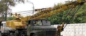
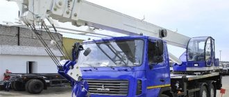
KS 3574 is an inexpensive and powerful Russian-made truck crane with wide functionality and universal capabilities. Despite the fact that the design of the machine was developed quite a long time ago, it is still in steady demand due to its excellent technical data. The undoubted advantages of the KS 3574 crane are functionality, maintainability and reliable technical solutions. The outdated appearance of the truck crane cabin does not affect the overall impressiveness of the vehicle due to its high ground clearance, large wheels and massive wheel arches. Such design features provide off-road characteristics of the equipment.
Description
The design of the KS 3574 “Ivanovets” truck crane was developed many years ago and has stood the test of time. The potential built into the car by engineers allows it to remain relevant and in demand in many countries to this day. The vehicle is equipped with a robust design, adapted for unloading and loading operations in the construction industry. The crane installation is based on a vehicle chassis borrowed from the Ural-5557 military truck. The equipment can be used for lifting and transporting loads over long distances.
Where can I use the KS-3574 crane
The Ivanovets truck crane is preferred for lifting operations for several reasons. Here we are not only talking about the high cross-country ability of the vehicle. Despite the fact that the technique was developed a long time ago, it is not at all outdated and has retained its versatility.
Construction sector
The KS-3574 truck crane has an almost ideal design in terms of endurance, and therefore it can be used professionally on construction sites where long-term and continuous work occurs when lifting heavy elements.
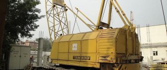
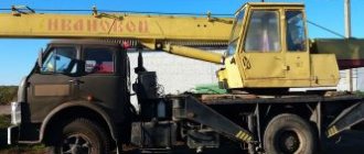
Truck crane KS-3574 in operation
Logistics centers and warehouses
The technique is safe and practical. It is used instead of manipulators if the power of the latter does not allow complex loading and unloading operations. Due to its compactness, the truck crane can work even in cramped warehouse conditions.
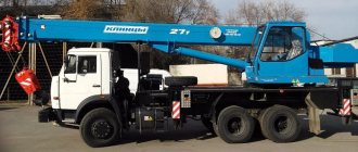
Truck crane URAL KS-3574 - general characteristics
Installation of bulky structures
Thanks to the function of free movement of cargo, both vertically and horizontally, the machine can be used when installing technical devices, various structures, and working with oversized cargo.
Elimination of consequences of natural disasters
Using a truck crane, it is convenient to remove rubble and load damaged structures and equipment. And thanks to the high cross-country ability of the KS-3574, this can be done in the absence of free access roads.
Scope of application
Thanks to its practicality and safety, the KS 3574 is in demand in the professional field and is used in logistics centers as manipulators, replacing similar machines of insufficient power. A functional and high-tech truck crane can be used for the construction of structures, buildings and technical structures. One of the machine’s options is the ability to move cargo in vertical and horizontal directions. In addition, the Ivanovets can be used to work at the sites of accidents and other disasters, allowing one to clear rubble and remove large cargo, which is why the vehicle is in demand among the special services of the Ministry of Emergency Situations.
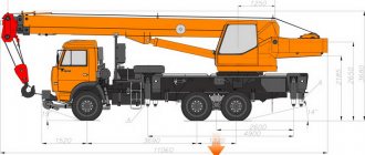
Technical characteristics of KS 3574
Main characteristics:
- Curb weight - 17.8 tons;
- Engine power - 210 horsepower;
- Fuel consumption - 43 liters per 100 kilometers;
- Maximum load capacity - 14 tons;
- Resistance to rollover - 45 tm;
- The maximum lifting height of the boom is 14.5 meters;
- Boom length - 14 meters;
- Speed limit - 60 km/h;
- Crane length - 9910 mm;
- Height - 3360 mm;
- Width - 2500 mm.
Features of design and operation
The KS 3574 truck crane is equipped with a telescopic boom, which is adjusted using a hydraulic pump. Torque is transmitted from the engine to the boom through a transmission, which allows it to be extended up to 14 meters. The selection of gear ratios in the box is carried out in such a way that it can withstand high loads. The crane installation is very compact and maneuverable due to the small space occupied by the boom in the shortened position. Thanks to this feature, the KS 3574 can work in confined spaces, while maneuvering well and performing a wide range of work.
In comparison with analogues and competitors, the Ivanovets crane installation is distinguished by high quality workmanship and reliability, which is its undeniable advantage over more expensive models. This also includes high technical equipment and versatility. KS 3574 is equipped with various sensors that simplify control and make it more efficient. One of the mechanisms allows you to adjust the boom lift angle and limit it. The truck crane is also equipped with sensors for controlling boom length, load capacity, and limiters for rewinding the cable and lifting the hook suspension. A special system limits the tension of the cargo rope.
Almost every moving part of the truck crane is equipped with sensors, which allows you to control all parts of the crane installation. The central computer receives information from the sensors and processes it, after which it transmits all data on the state of systems and mechanisms to the display of the on-board computer. The system allows the driver to monitor the condition of the truck crane, be aware of problems and fix them in a timely manner, which helps to avoid serious problems.
The KS 3574 truck crane is created on the basis of the chassis of a military truck of the same name, characterized by outstanding off-road capability. Tires with an impressive tread provide the ability to overcome various hard-to-reach routes, thanks to which the machine has gained popularity and become in demand not only in the construction industry, but also in the field of prospecting and development of minerals, gas and oil fields.
Compact dimensions, relatively light weight, a powerful diesel engine and an energy-intensive chassis ensure a smooth and maneuverable ride and excellent dynamic characteristics. KS 3574 can move on city highways at a speed of 60 km/h, and the speed picks up quite quickly, which is quite surprising for a car.
The retractable boom allows the truck crane to operate in a 360-degree circular area and lift loads located at a great distance from the vehicle chassis. The machine's security system is represented by a special element - a kind of “black box” that records the operating process of the equipment in real time. Throughout the entire operational life, the flight recorder records all important information.
MANIPULATING CRANES, CMU UNITS, TRUCK CRANES
_____________________________________________________________________________________________
Design of equipment and mechanisms of the KS-3574 truck crane
Fixed part The fixed part of the KS-3574 truck crane is the supporting base for the rotating part. The non-rotating part includes: a vehicle chassis, a support frame with outriggers, a spring locking mechanism for the rear chassis suspension, a pump drive and a rotating support. Chassis For the KS-3574 truck crane, the Ural-5557 cross-country chassis is used. Some chassis elements undergo minor alterations before installation of the crane installation. Support frame The support frame of the KS-3574 truck crane is a rigid welded structure consisting of a middle part made in the form of two longitudinal beams, transverse beams and a support ring for attaching the rotary support.
Fig.1. Support frame of truck crane KS-3574 1 - middle part; 2 — chassis spar; 3 - support ring; 4 — clamps of outriggers in transport position; 5, 8, 12 — bolts; 6, 7, 10 — nuts; 9 — set of gaskets; 11 - spring; 13 - transverse beam; 14 — base of the hydraulic tank Outriggers of the KS-3574 truck crane The outriggers of the KS-3574 truck crane are retractable and are welded box-section beams, at the ends of which hydraulic cylinders 1 for hanging the crane are fixed. The design of hydraulic cylinders 1 is the same as on the KS-3577-4 crane. Retractable outriggers 4 are mounted in the transverse beams of the support frame.
Extension and retraction of the outrigger support of the KS-3574 truck crane is carried out by hydraulic cylinder 5, the rod of which is fixed to the outrigger support, and the body is fixed to the transverse beam of the frame. In the transport position, the outriggers, in order to prevent spontaneous extension, are locked with clamps 3, for which the handle 15 of the clamp must be set upward. Before extending the outriggers, the clamps must be turned off by installing all four handles of the clamps on the stops 14.
Rice. 2. External support for the KS-3574 truck crane 1, 5 - hydraulic cylinders; 2 — clip; 3 — outrigger lock in transport position; 4 — outrigger support; 6 — transverse beam of the support frame; 7 - ring; 8, 16 — axes; 9 - gasket; 10 — washer; 11 - bolt; 12 - crossbar; 13 — bracket; 14 — emphasis; 15 — lock handle; 17 — washer; 18 — cotter pin Locking mechanism for the rear suspension of the KS-3574 truck crane The locking mechanism for the rear suspension of the KS-3574 truck crane serves for a rigid connection with the support frame of the middle and rear axles of the Ural-5557 chassis. The suspension locking mechanism consists of levers 6 and 7 hinged on axles 14, which are connected by rods 5 to spring brackets mounted on the axle housings of the middle and rear axles of the Ural-5557 chassis. A hydraulic cylinder 11 with a locking wedge 15 on the rod is attached to the lever 7. When the KS-3574 truck crane moves in the transport position, the locking wedge 15 is pulled by the cylinder rod 1 into the sleeve 12 of the lever 7. In this case, the levers 6 and 7 rotate freely relative to each other and do not interfere with the movement of the middle and rear chassis axles. When operating in crane mode, the locking wedge must be extended by the hydraulic cylinder rod, as shown in section A - A. In this case, a rigid connection of levers 6 and 7 is ensured and reliable blocking of both axles is ensured. In this case, indicator flags 8 and 10 for the activation mechanism of the suspension locking mechanism of the KS-3574 truck crane must be in a vertical position. To avoid turning the brackets on the axle axle housings, the brackets have welded stops 2 and screw stops 1.
Fig.3. Locking mechanism for the rear suspension of the KS-3574 truck crane 1 - screw stop; 2 - emphasis; 3 — bracket; 4 - nut; 5 - traction; 6, 7 — levers; 8.10 J pointers; 9, 13 — oilers; 11 — hydraulic cylinder; 12 — bushing; 14, 16 — axles; 15 - locking wedge; 17 - seal; 18, 21 — locking screws; 19 - nut; 20, 22 - crackers; 23 — stop Two-section telescopic boom of the KS-3574 truck crane The boom of the KS-3574 truck crane consists of a base 3, a retractable section 2, turning into a head with blocks 1, and a hydraulic cylinder 4 for extending the section. The base and retractable section of the boom are welded box-shaped structures. The boom section is moved by a hydraulic cylinder 4, which is fixed by a rod on the base of the boom with an axis 13, and by the body - on the retractable section using a special articulated joint consisting of a hinge 7, axes b and bushings 8, which makes it possible to compensate for all distortions that arise during operation and installation. When moving, the boom section of the KS-3574 truck crane rests in front on carriages 28 with rollers 29, mounted on the base of the boom using an axis 26, and at the rear on rollers 18, mounted on axles 20 in the jaws 21, hinged with an axis 19 in the boom section. In the retracted position, the boom section rests on shoe 5. Rollers 18 and carriages 28 are adjusted in width by spacer washers 24 and 27. To support the rope, the boom is equipped with rollers 31.
Fig.4. The boom of the KS-3574 truck crane is two-section telescopic 1 - block; 2 — boom section; 3 — boom base; 4 - hydraulic cylinder; 5 - shoe; 6, 9, 13, 19, 20, 22, 26, 30 - axles; 7- hinge; 8, 12 — bushings; 10, 14 — bearings; 11 — roller; 15 — washer; 16 — thrust washer; 17 - nut; 18, 29 — rollers; 21 - cheek; 24, 27 — spacer washers; 23, 25 — oilers; 28 — carriage; 31 - roller Automatic control systems for the load limiter of the KS-3574 truck crane. On the KS-3574 truck crane KS-3574, an automatic load limiter system (hereinafter referred to as the load limiter) of the ACS OGP-2A (or 2B, 2G) version is installed, which ensures the shutdown of the crane mechanisms when working with unacceptable loads. The load limiter of the ACS OGP consists of a decisive indicator device 8 (Fig. 5) installed on the instrument panel in the crane operator’s cabin; power supply 20 installed on the rear wall of the crane operator's cabin; two pressure sensors 7; boom length sensor 4; boom angle sensor 6; The decisive indicator device is a microprocessor device that processes sensor signals, generates commands to turn off the mechanisms of the KS-3574 truck crane when the maximum permissible overturning moment is reached or the boom leaves the working area and outputs information to four-digit digital and light indicators: - actual load of the truck crane in percent from the permissible load; — boom length in meters; — maximum permissible cargo weight in tons at the specified boom length and radius; — hook reach in meters; — light indicator of limiter operation; — light indicator of limiter malfunction; — light indicator of truck crane overload. On the front panel of the decisive indicator device there is also an operating mode switch 25 and a cover 26 covering the trimming potentiometers. Power supply 20 (Fig. 5) is designed to provide power to the load limiter of the KS-3574 truck crane. The block is equipped with a toggle switch 18 for turning on the limiter and fuse 19. The block is powered from the crane's electrical network with a voltage of 24 V through a plug connector, and all output stabilized voltages: 3 V, 5 V, 15 V, minus 5 V and minus 15 V are connected to the plug connector X2. The unit has a control and overvoltage protection device at the output of each power source. The sensors of the load limiter of the KS-3574 truck crane are designed to convert the corresponding parameters into electrical signals sent to the critical indicator device of the limiter. The boom angle sensor 6 (Fig. 5) consists of a housing in which a non-resistance potentiometer is installed. The sensor body is fixed to the bracket 22 of the rotating frame, and the potentiometer axis, through the driver 23 and the pin fixed to the base of the boom 5, receives angular movement when the angle of inclination of the boom changes. The boom length sensor 4 is installed on the base of the boom 5. It consists of a ten-turn potentiometer 11 (Fig. 7), which is fixed in the base 2. The axis of the potentiometer is connected to the drum 1 through a driver 8. It is fixed to the drum using a clutch 11 (Fig. 5) the ends of two ropes 2 and 3. The second end of the rope 3 is secured through a deflection roller 10 to the rear of the boom section of the KS-3574 truck crane at point E, and the second end of the rope 2 is secured to the front of the section through a spring 16. When the boom section moves, one of the ropes is unwinded from the drum, and the second is wound onto it, ensuring rotation of the drum and the associated axis of the potentiometer 11 (Fig. 7). Spring 16 (Fig. 5) provides the necessary tension on ropes 2 and 3 and laying of the ropes in the grooves of the drum. The contacts of the potentiometer 11 (Fig. 7) are connected by wires to the plug insert 15. The KS-3574 truck crane device can operate in the following modes: - “control” mode - for self-monitoring of the device. If the device is working properly in this mode, numbers from 0 to 9 are sequentially displayed on the digital indicators, and after this a short-term display of service information occurs - the type of faucet, the date of manufacture of the device program and the checksum of the read-only memory device; — YUST-1, YUST-2 modes are used to configure and test sensors;
— mode I — operation of a truck crane with the main boom; — mode II — operation of a truck crane with the main boom and jib. Modes are switched using the “control-mode” switch. Pressure sensors 7, installed on the rotating frame, are designed to measure the pressure of the working fluid in the piston and rod cavities of the hydraulic cylinder 9 (Fig. 5) for lifting the boom.
Rice. 5. Installation of the load limiter of the ACS OGP on the KS-3574 truck crane 1 - boom section; 2, 3 — ropes; 4 — boom length sensor; 5 — boom base; 6 — boom angle sensor; 7 — pressure sensors; 8 — decisive indicator device; 9 — boom lift hydraulic cylinder; 10 — deflection roller; 11 - coupling; 12 - bolt; 13, 17 — nuts; 14 - axis; 15 - traction; 16 - spring; 18 — toggle switch for turning on the load limiter; 19 - fuse; 20 — power supply; 21 — boom length sensor drum; 22 — bracket; 23 - leash.
Rice. 7. Boom length sensor for truck crane KS-3574 1 - drum; 2 - base; 3 — spacer ring, 4, 6, 12 — retaining rings; 5 - bearing; 7 - screw; 8 - leash; 9 - cover; 10 - nut; 11 — potentiometer SP5-44-01-1 kOhm; 13 - plug; 14 — tourniquet; 15 — plug insert.
_____________________________________________________________________________________________
_____________________________________________________________________________________________
- Main equipment and parameters of Unic CMU
- Operation of the Unic crane installation
- Palfinger CMU design
- Palfinger manipulator overload protection system
- CMU Hiab 190
- Hiab XS 320 loader crane
- Hiab 100/120 hydraulic manipulator
- CMU Tadano
- CMU Amco Veba
- KMU Fassi
- CMU Dongyang SS1506
_____________________________________________________________________________________________
- Equipment KS-35714
- Hydraulic system KS-35714, KS-35715
- Equipment and mechanisms KS-3577-4
- Recommendations for repairing KS-3574
- Hydraulic equipment KS-55713
- Repair of telescopic boom KS-55713-1K-3
- Parts and mechanisms of the rotating part KS-45717-1
- Design and controls KS-4572, KS-45719
- Operation of hydraulic equipment KS-45721, KS-45715
- Device KS-55727
- Review of the KS-6476 design
- Maintenance of KS-3579
- Adjustments KS-35719
- Truck crane KS-3575
- Crane KS-5576 Ivanovets
- Truck crane KS-5473 Dnepr
- XCMG QY25K5S truck crane
- Crawler crane MKG-25 BR
- Repair of chassis DEK-251
- Crane RDK-250
Modifications
Serial production of the KS 3574 truck crane has been carried out since the early 90s at the facilities of the Klintsovsky RMZ, the Ivanovo truck crane plant and in the city of Uglich. At the Ivanovo Truck Crane Plant, according to a special order from the Moscow Region, production of special modifications began:
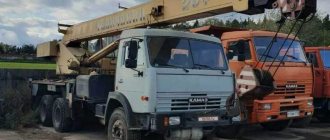
- KS 3574M. Made on the basis of the Ural-5571-01 chassis with a maximum load capacity of 12.5 tons.
- KS 3574M1. Based on the Ural-5557-31 chassis with a load capacity of 16 tons.
- KS 3574M2. Based on the KamAZ-53501 chassis with a maximum load capacity of 16 tons.
- KS 3574M3. Based on the Ural-4320-1058-01 chassis with a lifting capacity of 16 tons.
About the design of a truck crane
The Ivanovets truck crane is mounted on the chassis of a URAL model 5557 truck. All working mechanisms operate using hydraulics. A hydraulic pump drives fluid under pressure through the system.
Truck crane KS-3574 - hydraulic distributor diagram
Through the hydraulic distributor, this fluid enters one or another power unit, bringing it into action.
The truck crane cabin on a powerful frame is capable of rotating at a full circular angle and allows the operator to reach loads almost along the entire perimeter.
The safety system of the crane installation is based on standard limiters and a variety of control sensors. Computer-processed information about the condition of the equipment is transmitted to the screen of the control device in the driver’s cabin.