What is meant by crane operating cycle?
The crane operation cycle consists of 3 parts:
- Capture of cargo by equipment.
- The working stage is transporting, rearranging and unloading objects.
- Idling - return of the transport and lifting mechanism to the starting point and state to begin the next cycle.
Modern lifting vehicles are divided into several groups of operating modes depending on the number of cycles implemented over the entire period of operation. There are 10 classes C0 - C9. C0 is a type of crane device, the number of cycles of which corresponds to a value of no more than 1.6 * 10000, and C9 - from 4 * 1000000 and more. For types of special equipment C1 - C8, the figure varies within the range of 3.2 * 10000 - 2 * 1000000.
Technical standards and conditions determine the number of possible operations for moving to the load and to the starting position, lifting the object to a height. Depending on this, the types of cranes are distinguished:
- stationary;
- adjustable;
- radial;
- mobile;
- self-elevating
Another classification is based on design features: types of general drive, shape and differences of the load-handling element, possible degree of rotation, type of support and other design solutions.
Ie.:
ABOUT)
Рп – rated load capacity of the crane.
The values of the load distribution coefficient corresponding to the loading classes and a description of the nature of the crane loading corresponding to each class are given in Table 3.
Table 2 - Crane use classes
| Usage class | Number of operating cycles and service life. WITH, | Implementation examples |
| Up to 1.6 x 14 incl. | Irregular use, for 10 years no more than 5-10 cycles of operation per day | |
| And. | Se. 1.6 x 10⁴ to 3.2 x 10⁴ excl. | |
| «2 | Se. 3.2 x 10* to 6.3 x 10* excl. | Irregular use and within 10 years no more than 20-35 cycles of operation per day |
| "z | Se. 6.3 *10* to 1.25 x 10s excl. | |
| Se. 1.2S x 105 to 2.5 x 10s excl. | Regular use for 10 years no more than 70 cycles of operation per day | |
| Se. 2.5 x 10s to 5.0 x10⁵ incl. | Regular use for 10 years no more than 140 cycles of operation per day | |
| Se. S.0 x 10s to 1.0 x 10s incl. | Regular use for 20 years no more than 140 cycles of operation per day | |
| i7 | Se. 1.0 x 10e to 2.0 x 10* excl. | Intensive use for 20 years more than 140 cycles per day |
| Se. 2.0 x 10e to 4.0 x 10* excl. | ||
| V* | Se. 4.0×10⁶ |
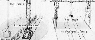
For cranes with a variable load characteristic in formula {1), the value P„ should be taken equal to the minimum load capacity established within the load movement zone (P„(I) in Figure 1. a). For cranes with several load characteristics, the load distribution coefficient should be calculated using formula (1}, taking as Р/Рп the ratio of the maximum load moment during the crane operating cycle to the load moment at the same outreach for the maximum load characteristic (РпаРш in Figure 1. b) ).
R
b)
R
Figure 1 - Towards the calculation of the load distribution coefficient for cranes with variable load characteristics (a) and several load characteristics (b).
3
GOST 34017—2016
Table 3 - Load classes
| Load class | Implementation examples | |
| Oh - especially light | Up to 0.062 incl. | The crane always operates with loads less than 50% of its lifting capacity. In special cases (no more than 4%) lifting larger loads |
| Og—light | St. 0.062 to 0.125 incl. | Constant work with loads that are significantly less than the rated lifting capacity of the crane (65% of loads are less than 50% of the lifting capacity) |
| Oa - average | Se. 0.125 to 0.250 incl. | Working with loads less than the rated lifting capacity of the crane, with periodic lifting of loads close to the rated lifting capacity (65 14 loads less than 50% of the lifting capacity) |
| Od - heavy | St. 0.25 to 0.50 incl. | Frequent work with loads close to the rated load capacity (75% of loads are more than 50% of the load capacity) |
| Qs—very heavy | St. 0.50 to 1.00 incl. | Constant work mainly with loads close to the crane's rated lifting capacity |
6.4 The crane operating mode classification group is generally determined by a combination of use class and load class according to Table 4.
Table 4 is constructed in such a way that for all combinations that provide one group of mode A, the value of the RPC product is the same. This is related to that. that for elements of a metal structure, in which the range of stress changes is proportional to the mass of the load, the product Krs is approximately proportional to fatigue damage. If only the Line classification group is specified for the crane, load and use classes are specified, then in the calculations you should take the Od class and find the corresponding use class from Table 4.
Recommendations for assigning operating mode classification groups for individual types of cranes are given in Appendix A.
Table 4 - Crane operating mode classification group
| Load class and load distribution factor | Class of use and values C(10*4 | ||||||||||
| Od | Kr | o0 1.6 | O. 3.2 | "G 6.3 | Oj 12.5 | 25 | o8 50 | o6 100 | From 200 | o8 400 | >400 |
| Oh | 0.062 | — | — | 40 | 41 | A2 | 43 | 44 | 45 | 46 | 47 |
| o2 | 0.125 | — | 40 | 41 | 42 | AZ | 44 | 45 | 46 | 47 | 48 |
| O, | 0.250 | 40 | 41 | 42 | 43 | 44 | 45 | 46 | 47 | 48 | 49 |
| Od | 0.500 | 41 | 42 | 43 | 44 | 45 | 46 | 47 | A6 | 49 | 410 |
| About | 1.000 | 42 | 43 | 44 | 45 | 46 | 47 | 48 | 49 | 410 | 411 |
Classification of cranes by operating mode
Depending on the scope of application, lifting equipment can be operated with different intensity and frequency. Regulatory documents regulate the operating mode groups of the crane and its mechanisms.
Russian regulations distinguish 6 categories, differing in the combination of degree of loading and class of use. The last parameter depends on the operating time standards of the mechanism and varies from A0 (light operation of the crane) to A6 (high degree of operation). Functioning with average intensity corresponds to indicator a3, high intensity in 3 shifts - a5.
According to the degree of loading, the following types of crane mechanisms are distinguished:
- IN 1. Minimum loads with a small number of braking and starting. Moving light weight loads.
- AT 2. The basis is medium and minimal loads with periodic starts and braking. Limited movement area.
- AT 3. Medium loads dominate, with heavy operations sometimes occurring. Large mass of objects being moved, small area of movement, constant braking and starting.
- AT 4. The basis is maximum loads. Limited maneuverability area, large mass of moving objects, constant braking and starting.
The correspondence of the 2 considered values is expressed by a separate coefficient: 1K - 8K. 3k is characterized by system operation from 800 to 1600 hours (1m-2m). To configure transport, they rely on a minimum threshold.
LOAD-LIFTING CRANES
Classification of operating modes
(ISO 4301-1:1986, NEQ) (ISO 4301-2:2009, NEQ) (ISO 4301-3:1993, NEQ) (ISO 4301-4:1989, NEQ) (ISO 4301-5:1991, NEQ)
Official publication
Moscow
Form standards
2017
GOST 34017—2016
Preface
The goals, basic principles and basic procedure for carrying out work on interstate standardization are established in GOST 1.0-2015 “Interstate standardization system. Basic provisions" and GOST 1.2-2015 "Interstate standardization system. Interstate standards, rules and recommendations for interstate standardization. Rules for development and acceptance. updates and cancellations"
Standard information
1 DEVELOPED by Joint Stock Company "RATTE" {JSC "RATTE")
2 INTRODUCED by the Federal Agency for Technical Regulation and Metrology
3 ADOPTED by the Interstate Council for Standardization, Metrology and Certification (protocol dated November 22, 2016 No. 93-P)
The following voted for adoption:
| Short name of the country according to MK (ISO 3166) 004-97 | Code of the country according to MK (ISO ZTvv) 004-97 | Abbreviated name of the national standardization body |
| Armenia | A.M. | Ministry of Economy of the Republic of Armenia |
| Belarus | BY | State Standard of the Republic of Belarus |
| Georgia | G.E. | Gruzstandart |
| Kazakhstan | To Z | Gosstandart of the Republic of Kazakhstan |
| Kyrgyzstan | KG | Kyrgyestvndart |
| Russia | RU | Rosstandart |
| Tajikistan | T.J. | Tvdzhikstandard |
| Uzbekistan | UZ | Westndart |
4 By order of the Federal Agency for Technical Regulation and Metrology dated March 17, 2022, Ns 150-st interstate standard GOST 34017-2016 was put into effect as a national standard of the Russian Federation on January 1, 2022.
5 8 this standard takes into account the main regulatory provisions of the following international standards: ISO 4301/1—86 “Cranes and lifting devices. Classification. Part 1. General provisions" (“Cranes and lifting appliances - Classification - Part 1: General", NEQ); ISO 4301 -2:2009 “Lifting cranes. Classification. Part 2. Self-propelled cranes" ("Cranes - Classification - Part 2: Mobile cranes", NEQ): ISO 4301-3:1993 "Lifting cranes. Classification. Part 3. Tower cranes" ("Cranes - Classification - Part3: Tower cranes". NEQ); ISO 4301-4:1989 “Cranes and lifting devices. Classification. Part 4. Jib cranes" ("Cranes and related equipment - Classification - Part 4: Jib cranes." NEQ); ISO 4301-5:1991 “Cranes. Classification. Part 5. Bridge and gantry cranes" (“Cranes - Classification - Part 5: Overhead travelling and portal bridge cranes", NEQ)
6 INSTEAD OF GOST 25546-82 and GOST 25835-83
GOST 34017—2016
Information about changes to this standard is published in the annual information index “National Standards”. and the text of changes and amendments is in the monthly information index “National Standards”. In case of revision (replacement) or cancellation of this standard, the corresponding notice will be published in the monthly information index “National Standards”. Relevant information, notifications and texts are also posted in the public information system - on the official website of the Federal Agency for Technical Regulation and Metrology on the Internet ()
© Standardinform. 2017
In the Russian Federation, this standard cannot be reproduced in whole or in part. replicated and distributed as an official publication without permission from the Federal Agency for Technical Regulation and Metrology
in
GOST 34017—2016
Content
1 Scope……………………………………………1
2 Normative references……………………………………………………..1
3 Terms and definitions…………………………………………1
4 Designations and abbreviations…………………………………….2
5 Purposes of applying the classification of operating modes of cranes and mechanisms……………..2
6 Classification of operating modes of cranes in general……………………………2
7 Classification of operating modes of mechanisms……………………………..4
Appendix A (recommended) Classification of operating modes of certain types of cranes
and their mechanisms………………………………………………………7
IV
GOST 34017—2016
Introduction
This standard establishes a classification of operating modes of cranes and their mechanisms according to the parameters of load and operating time and service life. This classification is intended for standardization. forecasting and assessing the durability of these objects at the stage of ordering, design and operation.
Application of the provisions of this standard on a voluntary basis can be used to confirm and assess the compliance of load-lifting cranes with the requirements of the Technical Regulations of the Customs Union “On the safety of machinery and equipment” (TR CU 010/2011).
V
GOST 34017—2016
INTERSTATE STANDARD
LOAD-LIFTING CRANES Classification of operating modes
Cranes. Classification of operating modes
Date of introduction: 2018—01—01
1 area of use
This standard establishes a classification of operating modes of cranes and their mechanisms according to the parameters of load and operating time during their service life. This standard applies* to all types of load-lifting cranes in accordance with GOST 33709.1. as well as floating and offshore cranes.
This standard applies to all new cranes manufactured after one year of approval. The standard is not intended to require replacement or modernization of existing documentation.
2 Normative references
This standard uses normative references to the following interstate standards:
Lifting cranes. Dictionary. Part 1. General provisions Lifting cranes. Dictionary. Part 2. Self-propelled jib cranes Load-lifting cranes. Dictionary. Part 3. Tower cranes Load-lifting cranes. Dictionary. Part 5. Overhead and gantry cranes
GOST 33709.1—2015 GOST 33709.2—2015 GOST 33709.3—2015 GOST 33709.5—2015
GOST 33713—2015 Lifting cranes. Operating parameters recorders. General requirements
vania
Note - When using this standard, it is advisable to check the validity of the reference standards in the public information system - on the official website of the Federal Agency for Technical Regulation and Metrology on the Internet or using the annual information index "National Standards", which was published as of January 1 of the current year, and on issues of the monthly information index “National Standards” for the current year. If the reference standard is replaced (changed), then when using this standard you should be guided by the replacing (changed) standard. If the reference standard is canceled without replacement, then the provision in which a reference to it is given applies to the part that does not affect this reference.
3 Terms and definitions
This standard uses terms according to GOST 33709.1 and GOST 33713, as well as the following term with the corresponding definition:
crane operating cycle: A fragment of the crane operating process that begins when a load exceeds 5% of the rated net lifting capacity appears on the load-handling member, and ends when the load drops to less than 5% of this value.
Official publication
1
GOST 34017—2016
4 Symbols and abbreviations
The designations adopted in this standard are given in Table 1.
Table 1 - Accepted designations
| Designation | Definition |
| A | Crane operating mode classification group |
| ABOUT | Crane load class |
| And | Crane usage class |
| M | Mechanism operating mode classification group |
| L | Mechanism load class |
| T | Mechanism usage class |
| R | Load value on crane or mechanism |
| St | Total number of crane operating cycles over its service life |
| Kr | Mass distribution coefficient of transported loads |
| Ht | Mechanism load distribution coefficient |
5 Purposes of applying the classification of operating modes of cranes and mechanisms
The classification of operating modes of cranes and mechanisms is based on the load and operating hours of the corresponding objects. The classification is intended for use in the following situations:
a) to formulate customer requirements for the durability of the crane or individual mechanisms when placing an order. 8 In this case, load and operating hours indicators are determined based on the expected operating conditions of the machine;
b) when designing a crane or mechanism. In this case, the values of load and operating time indicators for the established operating mode are used to calculate the durability of the elements of the crane or mechanism;
c) when monitoring the operation of a crane or machinery. In this case, the actual load and operating time indicators obtained from the parameter recorder (GOST 33713) or other sources of information are compared with the indicators of the standard operating mode of the crane or mechanism. Based on this, a decision is made on the possibility of further operation or the need for restoration measures.
6 Classification of operating modes of cranes in general
6.1 The crane operating mode classification group is determined by two indicators characterizing the operational loading conditions of the structure:
• class of use, depending on the number of cycles of operation of the crane during the designated service life;
• load class, which depends on the distribution of the relative masses of the transported goods.
6.2 The class of use is characterized by the operating time indicator - the total number of operation cycles of the crane over the service life C,. The range of possible values of C is divided into 10 intervals, each of which corresponds to a specific class of use (Table 2). Table 8, Table 2 also shows examples of crane operating intensity corresponding to each class. The parameter used for durability calculations is the upper limit of the interval.
6.3 The load class is characterized by a relative load indicator - the load distribution coefficient Kp, which is calculated as
2
GOST 34017—2016
where C, -
C,=
average number of cycles of crane operation with a load of mass P;
Re-registration
The number assigned when registering the lifting structure is retained until the end of use of the unit. However, the rule applies to equipment with one owner.
Re-registration of cranes in the Rostekhnadzor department is required for lifting equipment after:
- reconstruction works;
- major repairs (if a new technical passport has been drawn up for the equipment);
- moving the bridge unit to another permanent site.
It is necessary to deregister equipment at the RTN department if:
- failure of the device and decommissioning from the list of company objects;
- transfer of the device to the category not subject to registration after reconstruction.
The company must submit a written application and a technical equipment passport with recorded reasons for re-registration or removal of the object from the list of registered ones.
Work cycle
To carry out various construction, repair, as well as installation and loading and unloading work, a crane is used, which must meet the requirements specified in GOST and SNiP. A modern crane is a special lifting machine with cyclic action. The operating cycle of such a PS consists of three main stages, that is, capturing the load itself, as well as working and idling. Where the working stroke represents the unloading and movement of a wide variety of cargo, and the idle stroke is the return of this conventional lifting mechanism to its original position for further work.
Work factors
The operation of a modern crane must comply with the general cycle use class and also meet the requirements of ISO 4301/186. The operation of this structure must be carried out in accordance with the adopted GOST 2755587. The operation of the cranes must be safe and carried out in accordance with the parameters of the operating mode and cyclicity. Here it is necessary to take into account such an important factor as the number of cycles per unit of total time. If the cyclicity, as well as the frequency of switching on and subsequent switching off, does not comply with the requirements of GOST and SNiP, then the quality of work and the shelf life of such a lifting structure will be significantly reduced.
Usage class by number of cycles
Working modern cranes differ in their classes of use depending on the operating cycles throughout their service life. Such classes are divided into ten types, which are designated from C0 to C9. Where class C0 corresponds to the number of crane operation cycles equal to up to 1.6x10,000, and C9 has a number of cycles over the entire service equal to 4x1,000,000 or more. The remaining classes from C1 to C8 correspond to the number of cycles from 3.2x10,000 to 2x1,000,000 over the entire service life. Cycling usually includes a series of operations from moving to the load to lifting it and returning to its previous position for further work. The working life of each type of crane is established in technical conditions and standards according to the number of cycles that the crane can make over the total period of its operation. Such cranes are divided into stationary, radial, adjustable, self-climbing and mobile. They are also divided according to the type of common drive, degree of rotation, load-handling device, type of support and design solution. Cranes are also divided according to service life, general cyclicity of operation, main group, class and operating mode. Where the general operating mode of cranes must comply with GOST 2583583.
ANNEX 1
STATE STANDARD OF THE USSR UNION
CRANES LOAD
-LIFTING
MODES
OF OPERATION
GOST
25546 - 82
USSR STATE
COMMITTEE ON STANDARDS Moscow
STATE
STANDARD OF THE UNION OF THE USSR
| -LIFTING CRANES Operating modes Hoisting cranes. Work conditions | GOST 25546-82 |
Approved
by the Decree of the USSR State Committee on Standards of December 20 , 1982 . No. 4925
By Decree
of the State Standard of January 14, 1984 No. 67
validity period was established
from
01/01/86
to
01/01/91
validity period was extended to 01/01/92, IUS 9-90
The restriction was canceled, IUS 10-91.
Failure to comply
the standard is punishable by law
1. This standard applies to load-lifting cranes of all types (except ship and floating ones) and establishes groups of modes of their operation.
The standard corresponds to the international standard ISO 4301/1-86, with the exception of load class Q0.
The requirements of this standard are mandatory.
(Changed edition, Amendment No. 1).
2. The class of use, depending on the number of operating cycles of the crane during its service life, is determined from the table. .
Table 1
| Usage class | Total number of crane operating cycles over its service life |
| c0 | Up to 1.6×10⁴ |
| C1 | St. 1.6×10⁴ to 3.2×10⁴ |
| C2 | St. 3.2×10⁴ to 6.3×10⁴ |
| c3 | St. 6.3×10⁴ to 1.25×10⁵ |
| C4 | St. 1.25×10⁵ to 2.5×10⁵ |
| C5 | St. 2.5×10⁵ to 5×10⁵ |
| C6 | St. 5×10⁵ to 1×10⁶ |
| C7 | St. 1×10⁶ to 2×10⁶ |
| C8 | St. 2×10⁶ to 4×10⁶ |
| C9 | St. 4×10⁶ |
Notes:
1. The crane operating cycle consists of moving the load-handling member to the load, lifting and moving the load, releasing the load-handling member and returning it to its original position.
2. The service life of cranes is established in standards or technical specifications for specific types of cranes.
3. The load class, depending on the load factor, is determined according to the table. .
table 2
| Load class | Load factor, TO R |
| Q0 | Up to 0.063 |
| Q1 | St. 0.063 to 0.125 |
| Q2 | St. 0.125 to 0.25 |
| Q3 | St. 0.25 to 0.50 |
| Q4 | St. 0.50 to 1.00 |
4. The operating mode group of cranes, depending on the class of use and load class, is determined according to table. .
Table 3
| Usage class | Crane operating mode group for load class | ||||
| Q0 | Q1 | Q2 | Q3 | Q4 | |
| c0 | — | — | 1 TO | 1 TO | 2K |
| C1 | — | 1 TO | 1 TO | 2K | 3K |
| C2 | 1 TO | 1 TO | 2K | 3K | 4K |
| C3 | 1 TO | 2K | 3K | 4K | 5K |
| C4 | 2K | 3K | 4K | 5K | 6K |
| C5 | 3K | 4K | 5K | 6K | 7K |
| C6 | 4K | 5K | 6K | 7K | 8K |
| C7 | 5K | 6K | 7K | 8K | 8K |
| C8 | 6K | 7K | 8K | 8K | — |
| C9 | 7K | 8K | 8K | — | — |
5. The operating mode group of cranes transporting cargo heated above 300°C, or molten metal, slag, toxic, explosive substances and other dangerous goods must be at least 6K, with the exception of jib self-propelled cranes, for which the operating mode group must be at least 3K.
Load factor K
p is calculated using the formula
,
where Qi is the mass of the load moved by the crane with the number of cycles C
i;
Qnom - rated load capacity of the crane;
WITH
i is the number of cycles of operation of the crane with a load of mass Qi;
WITH
t is the number of operation cycles of the crane during its service life,
WITH
t = å
C
i.
Note. The mass value of the load-handling device hung on the crane hook or used to directly grab the load (grab, lifting electromagnet, spreader, etc.) is included in the values of Qi and Qnom.
6. In the absence of the initial data necessary to determine the load class and utilization factor, the mode group can be set according to the application data.
(Changed edition, Amendment No. 1).
7. The relationship between groups of crane operating modes and classes of use and loading of cranes according to this standard and groups of crane operating modes according to the international standard ISO 4301/1-86 is presented in the Appendix.
(Introduced additionally, Amendment No. 1).
Recommended
| Type of crane, its name | Operating mode group | Approximate objects, conditions of use and technological purpose of cranes |
| Manual taps of all types | ||
| Cranes with manual drive of all working mechanisms | 1 TO | Pumping and compressor stations, machine rooms of power plants, repair cranes with a small number of mechanisms being serviced, auxiliary cranes of machine shops |
| Cranes with manual drive of some working mechanisms and electric, hydraulic or pneumatic drive of the rest | 1 TO | Rarely used loading cranes, machine shop auxiliary cranes |
| 2K | Relatively commonly used loading cranes for loading workpieces onto processing machines | |
| Overhead type drive cranes | ||
| Cranes with driven suspended hoists, including those with mounted grips | 1 TO | Repair cranes |
| 2K | Reloading work of limited intensity, auxiliary cranes in machine shops, cranes intensively used only during equipment installation | |
| 3K | Medium-intensity handling work, cranes for transport and installation work in machine shops | |
| Cranes with winch load trolleys, including with mounted grippers | 2K | Machine rooms of power plants, repair cranes |
| 3K | Reloading work of limited intensity, auxiliary cranes in machine shops, cranes intensively used only during equipment installation | |
| Cranes with winch load trolleys, including with mounted grippers | 5K | Medium-intensity handling work, cranes for technological work in machine shops, lower timber warehouses, warehouses of finished products of building materials enterprises, metal sales warehouses |
| 7K | Technical cranes during round-the-clock operation | |
| Cranes with two-rope grabs, magnetic grab cranes | 6K | Mixed warehouses, handling a variety of cargo, mainly seasonal use |
| 7K | Warehouses for bulk cargo and scrap metal, work with homogeneous cargo, non-24-hour work | |
| 8K | Warehouses for bulk cargo and scrap metal with homogeneous cargo with 24-hour, year-round operation | |
| Magnetic taps | 6K | Warehouses for semi-finished products, handling a variety of cargo |
| 8K | Shops and warehouses of metallurgical enterprises, large metal warehouses, work with homogeneous loads (metal sheets in bags) | |
| Traverse, muldo-magnetic, muldo-grab, muldo-loading, for stripping ingots, piledriver, cupola charge, well cranes | 8K | Shops of metallurgical enterprises |
| Hardening, forging and pin valves | 7K | |
| Foundry cranes | ||
| Container cranes | 5K | Railway stations, warehouses of industrial enterprises, transshipment of various cargoes, including containers |
| Container cranes | 6K | The same, but reloading only containers |
| Grab cranes | 8K | Bulk cargo warehouses |
| Overhead and rack stacker cranes | ||
| Cranes with cab control and automatic action | 6K | Racking warehouses for containerized cargo |
| Floor controlled taps | 5K | |
| Jib cranes | ||
| Tower construction (jack-up, mobile, stationary) cranes | 3k | Installation of industrial buildings, structures and equipment (crane lifting capacity over 100 tons) |
| 4K | Servicing house-building factories and other specialized construction organizations; work in warehouses and testing areas of reinforced concrete products factories (crane lifting capacity per 100 tons) | |
| 7K | Hydraulic engineering maintenance | |
| Self-propelled jib (pneumatic, truck-mounted, crawler) cranes | 1 TO | Installation of industrial and energy equipment (crane lifting capacity over 100 tons) |
| 2K | Installation of industrial buildings and structures (crane lifting capacity from 25 to 100 tons) | |
| 3K | Loading, installation and construction work (load capacity up to 25 tons) | |
| Gantry cranes | ||
| Hook transfer cranes | 6K | Transport warehouse facilities |
| Grab cranes | 6K | Warehouses of industrial enterprises and ports during seasonal work |
| 8K | Warehouses and ports with round-the-clock, year-round operation | |
| Timber cranes with motor grab | 6K | Large round timber warehouses |
| Jib cranes | ||
| Mobile cranes | 6K | Foundries |
| Mobile cranes and column mounted | 4K | Reloading and auxiliary work |
| 2K | Maintenance of repair and installation work | |
| Cranes with load-bearing ropes (cable cranes) | ||
| Hook assembly cranes | 2K | Maintenance of installation works |
| Hook transfer cranes | 5K | Warehouses for piece and bulk cargo |
| Grab cranes | 7K | Bulk cargo warehouses |
Recommended
| Usage class | Crane operating mode group for load class | |||||||||
| Q0 | Q1 | Q2 | Q3 | Q4 | ||||||
| GOST 25546-82 | ISO 4301/1-86 | GOST 25546-82 | ISO 4301/1-86 | GOST 25546-82 | ISO 4301/1-86 | GOST 25546-82 | ISO 4301/1-86 | GOST 25546-82 | ISO 4301/1-86 | |
| c0 | — | — | — | — | 1 TO | — | 1 TO | A1 | 2K | A2 |
| C1 | — | — | 1 TO | — | 1 TO | A1 | 2K | A2 | 3K | A3 |
| C2 | 1 TO | — | 1 TO | A1 | 2K | A2 | 3K | A3 | 4K | A4 |
| C3 | 1 TO | — | 2K | A2 | 3K | A3 | 4K | A4 | 5K | A5 |
| C4 | 2K | — | 3K | A3 | 4K | A4 | 5K | A5 | 6K | A6 |
| C5 | 3K | — | 4K | A4 | 5K | A5 | 6K | A6 | 7K | A7 |
| C6 | 4K | — | 5K | A5 | 6K | A6 | 7K | A7 | 8K | A8 |
| C7 | 5K | — | 6K | A6 | 7K | A7 | 8K | A8 | 8K | — |
| C8 | 6K | — | 7K | A7 | 8K | A8 | 8K | — | — | — |
| C9 | 7K | — | 8K | A8 | 8K | — | — | — | — | — |
(Introduced additionally,
Amendment No. 1 ).
Which faucets are subject to registration?
The requirements for passing technical inspection and registering types of crane equipment are contained in the “Safety Rules for HPFs”, recorded by Rostechnadzor Order No. 533 of 2013 (clauses 3-4, clause 148). In some models, data on mandatory registration is indicated in the title page of the technical equipment passport.
Before starting the work process, the Rostekhnadzor authorities must approve:
- lifting crane units;
- bridge stackers equipped with a machine drive;
- cargo trolleys moving along ground rails along with the cabin, supplemented by an electric control system;
- excavator equipment operated with a hook on a rope or attached using an electromagnet;
- large-sized lifts;
- tower and rifle structures;
- gantry mechanisms;
- console units;
- standard cranes, etc.
However, it is necessary to take into account the exceptions fixed by law. The following are not subject to registration with Rostechnadzor:
- units with a permitted load capacity of up to 10 tons;
- equipment controlled from the floor using a push-button device attached to the faucet, as well as a remote control;
- jib cranes with a permissible weight of up to 1 t;
- shooting type crane equipment that has a fixed reach or is not equipped with a rotating system;
- cranes used for installation of pipelines, masts, beams, operated on a special static stand;
- units (towers, bridges) used on the sites of educational institutions when taking courses;
- electric hoists;
- overhead stacker cranes;
- crane structures on crushing and reloading equipment, excavators, spreaders;
- equipment that is used only for repair work (beam crane, etc.).
Registration of truck cranes by Rostechnadzor is also not required. Equipment not accounted for in the RTN department must be entered at the enterprise in the accounting book of crane installations and load-handling products under a separate number.
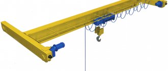
Gantry cranes
A. Sagizly,
Gantry cranes belong to the category of bridge-type lifting devices. The load-bearing elements of their design rest on the crane runway using two support posts. The average service life of gantry cranes is approximately 20 years, regardless of operating mode and operating conditions. MTBF is approximately 3,000 cycles.
In this article we will talk about gantry cranes with full electric drive. Based on their purpose, they can be divided into three groups. The first group is general purpose cranes with a relatively low lifting height (on average up to 12 m). They are used to service open storage and loading areas. The second group is construction gantry cranes for the installation of prefabricated building structures and equipment for industrial enterprises. The third group includes special-purpose structures (usually KKS) for servicing hydraulic structures, reloading large-capacity containers and long cargo.
Gantry cranes use a variety of load-handling devices: single-horned and double-horned hooks, grabs (bucket grabs for bulk cargo), lifting electromagnets of the M and PM series, special load-handling devices - tong grips, traverses, load frames, spreaders.
Depending on the bridge design, gantry cranes are divided into single-girder and double-girder. The lifting mechanism is mounted on a cargo trolley, which moves along the bridge. Depending on its purpose, the crane is equipped with one or two lifting mechanisms (main and auxiliary). The drive power and load capacity of the auxiliary lifting mechanism are, as a rule, less than the power of the main (main) one. The speed of such lifting mechanisms is also different - the auxiliary one is usually slower. There are, however, designs of gantry cranes in which both drives have the same characteristics and operate synchronously. Crane trolleys of this design are made of suspended monorail (load capacity up to 5 tons, less often - up to 10 tons), suspended double-rail, cantilever and cantilever-suspended. If the crane bridge is single-beam, electric hoists are used as the crane trolley, and in this case its path is a monorail guide (I-beam).
The cross-section of a gantry crane bridge can be tubular, box-shaped or lattice. Cranes with a double-girder bridge are more metal-intensive, but they have their own advantages, the main one of which is the ability to install trolleys from overhead cranes of standard designs, made using proven technology. Load trolleys of double-girder cranes are sometimes equipped with a rotating boom.
Typically, gantry cranes are made as double-cantilever cranes. The console is the part of the bridge that extends beyond the crane runway (support). The presence of consoles expands the working area of the cranes, for example, it makes it possible to service several access railways, highways and warehouse sites from one place.
The supports of gantry cranes are made of two posts of equal rigidity, or one support is rigid, the other is “flexible”. In such designs, the hinge mount is installed in the crane frame assembly. This technical solution allows you to compensate for skewing loads in the supporting units of the crane frame. Cranes are also manufactured with single-post supports. Structures with single-girder bridges and single-column supports are used when two cranes operate together.
The gantry crane is controlled from the floor or from a cabin that is attached to the trolley frame or to the crane bridge at the support. Its speed usually does not exceed 1 m/s. The lifting capacity of general purpose gantry cranes is 3.2…32 t, span length is 10…32 m, load lifting height is 7…10 m (less often – up to 12 m). The lifting capacity of construction cranes is greater - up to 400 tons, span length - up to 80 m, lifting height - up to 30 m.
The parameters of special-purpose gantry cranes are better - lifting capacity up to 900 tons, span length more than 130 m, lifting height up to 80 m. For example, to service hydroelectric power stations, cranes with a lifting capacity of 20...500 tons with a span length of 5...20 m are used. Such lifting mechanisms are sometimes equipped with additional lifting means - mounting boom, jib crane, etc.
Container cranes are used mainly to service large transshipment points - seaports, container terminals, railway stations. For work in a seaport they are equipped with a lifting console. The load-handling parts of container cranes are special cargo frames (spreaders) with automatic hooks for fittings and container yokes. The peculiarity of this configuration is that the crane is equipped with a special cargo trolley. The parameters of gantry container cranes with a lifting capacity of 20 and 32 tons are regulated by GOST 24390–99. The lifting height of these cranes is determined depending on the conditions for stacking containers, i.e., tiered storage. This class of crane equipment deserves a separate publication.
Grab and magnetic cranes are less common than general purpose cranes, since the tasks of reloading bulk cargo and cargo moved by electric magnets are solved mainly through the use of removable drive grabs and magnets with independent power and control. However, it must be remembered that cranes of these types must be equipped with special cargo trolleys - grab or magnetic, and the gripping elements (grab or magnet) must be supplied by the manufacturer as part of the crane. The magnetic crane must be equipped with a cable layer and a cable drum, the capacity of which corresponds to the lifting height of the magnet.
As of 2001, the total number of cranes in Russia was about 290 thousand, of which only 22 thousand were gantry cranes. At that time, about 85% of the cranes had already reached their standard service life. The trend towards aging equipment continues today, as the fleet of lifting cranes is updated extremely slowly. The production of cranes in Russia over the past 10...15 years has sharply decreased due to poor sales. According to Dr. Tech. Sciences, Professor, Honored Mechanical Engineer of Russia A.A. Zaretsky (PTO magazine No. 11, 12, 2001), in the next 25...30 years, predominantly obsolete and physically worn-out lifting equipment will be used in Russia. In such conditions, in order to avoid accidents and incidents, it is extremely important to strictly observe the rules for the design and safe operation of load-lifting cranes, and the requirements of other regulatory documents on safety.
Floor-controlled gantry cranes with a lifting capacity of up to 10 tons and a travel speed of up to 1 m/s are not subject to registration with the Gosgortekhnadzor; cranes with a larger lifting capacity are allowed for operation only after registration. Along with the registration documents, a certificate must be submitted confirming the compliance of the ground track with the loads of the crane being installed. For cranes manufactured abroad, a conclusion from the certification center of the Gosgortekhnadzor of Russia is presented as part of the registration documents. For a crane that has reached the end of its life, the registration documents must include a conclusion from a specialized organization on the possibility of its further operation. Permission to put a gantry crane into operation (after installation at a new location, after reconstruction, repair or replacement of design units of metal structures using welding) must be obtained from the Gosgortekhnadzor body that registered the machine.
According to Article 2.12 of PB 1038200, gantry cranes must be equipped with working movement limiters to automatically stop the lifting mechanism, the crane movement mechanism, regardless of the speed of movement and the movement mechanism of the load trolley. The kit should also include automatic skewing limiters, anti-theft devices (rail grips, etc.), and elastic buffer devices. Cranes of a mode group of at least A6 and a lifting capacity of more than 10 tons in accordance with ISO 4301/1 are equipped with work recorders - the so-called “black boxes”.
A brand system has been introduced that determines the procedure for admitting specialists to the crane in order to minimize accidents during the operation of a gantry crane as a result of uncoordinated actions of the driver and slingers, as well as workers engaged in repair or maintenance. The input device (protective panel) of the faucet is equipped with an individual contact lock with a key. The key mark is designed to close the control circuit and is a safety device; the registration number of the tap is stamped on it. The procedure for working with a key mark is defined in Appendix No. 1 of the Interindustry Rules for Labor Safety during Loading, Unloading, Lifting and Placement of Loads.
Currently, placing an order by a consumer for the manufacture and supply of a gantry crane requires serious technical preparation. The crane parameters that the consumer sets to the manufacturer will largely determine the effectiveness of its use in specific conditions.
For example, you can use a gantry container crane with a lifting capacity of 30.5 tons (bridge length 55 m, container lifting height up to 8 m), manufactured at the end of 2000 by the Kaliningrad joint stock company for the seaport of Petropavlovsk-Kamchatsky. This project was an individual development of just such a crane, which determined its technical parameters that corresponded to the parameters and operating conditions specified by the consumer.
When placing an order for the manufacture and supply of a new gantry crane, you should work with a reliable intermediary company or a technically competent broker who will be able to select a reputable crane manufacturer, organize and monitor the implementation of a set of works to create operational, complete equipment that complies with the technological regulations of the owner’s enterprise. He also organizes the delivery and installation of the crane at the enterprise site.
Causes and consequences of non-compliance with the work schedule
Setting the equipment classification group incorrectly will have unpleasant consequences. Early wear of cranes and mechanisms associated with this causes downtime and costs for repairs.
The reason for the discrepancy between the parameters is the banal desire to save money. When buying an overhead crane, the future owner chooses equipment that does not meet the requirements and does not correspond to the classification group. This often results in excessive wear and tear on the faucet preventing it from being used. And this happens even before the expiration of the service life provided for by the standards.
The discrepancy is expressed in very simple things. When purchasing crane equipment for “light” mode, the owner uses the crane around the clock and without interruptions. In this case, maximum loads are allowed. A series of breakdowns causes dissatisfaction among owners and unfounded claims against manufacturers.
How to determine the optimal operating mode of a crane
The operating mode of equipment is a technical characteristic that takes into account the load capacity, time and number of operating cycles when using it.
Today there are classification groups that determine the mode of operation. According to the ISO 4301/1 crane standard, there are only eight of them (A1-A8). Compliance with the group is determined by a combination of concepts such as class of use (U0-U9) and crane loading mode (Q1 -Q4).
Groups of classification (mode) of cranes in general
| Loading mode | Load distribution coefficient | Usage class | |||||||||
| U0 | U1 | U2 | U3 | U4 | U5 | U6 | U7 | U8 | U9 | ||
| maximum number of operating cycles | |||||||||||
| 1.6x10⁴ | 3.2x10⁴ | 6.3x10⁴ | 1.25x10⁵ | 2.5x10⁵ | 5x10⁵ | 1x10⁶ | 2x10⁶ | 4x10⁶ | more than 4x10⁶ | ||
| Q1 - light | 0.125 | A1 | A2 | A3 | A4 | A5 | A6 | A7 | A8 | ||
| Q2 - moderate | 0.250 | A1 | A2 | A3 | A4 | A5 | A6 | A7 | A8 | ||
| Q3 - heavy | 0.500 | A1 | A2 | A3 | A4 | A5 | A6 | A7 | A8 | ||
| Q4 - very heavy | 1.000 | A1 | A2 | A3 | A4 | A5 | A6 | A7 | A8 | ||
The class of use is a value that is determined by the number of lifting cycles performed by the equipment during its service life according to the standard. In fact, it depends on the amount of time the crane is moving.
One cycle is limited by the following concepts:
- moving the load gripper to the load;
- its lifting and moving;
- release of the load gripping body;
- returning it to its original position.
There is a formula for calculating work cycles. It allows you to calculate the number of work cycles that can be performed during the normal operation of the crane.
CT = Cс * Pdn * Tk, where
Сс – number of working cycles per day;
Pdn – the number of times per year when the crane is operating;
Tk – the number of complete years of operation of the equipment.
The value that characterizes the loading mode is the coefficient Kр. It shows the distribution of loads with a simple formula:
Where
Qi is a certain mass moved by the crane Ci times;
Qnom – nominal value of load capacity;
Ci is the number of cycles that lifts a load of mass Qi;
Ct – the total number of lifting cycles during the service life of the crane.
GOST 25546-82 Lifting cranes. Operating modes
STATE STANDARD OF THE USSR UNION
CRANES LOAD
-LIFTING
MODES
OF OPERATION
GOST
25546 - 82
USSR STATE
COMMITTEE ON STANDARDS Moscow
STATE
STANDARD OF THE UNION OF THE USSR
| -LIFTING CRANES Operating modes Hoisting cranes. Work conditions | GOST 25546-82 |
Approved
by the Decree of the USSR State Committee on Standards of December 20 , 1982 . No. 4925
By Decree
of the State Standard of January 14, 1984 No. 67
validity period was established
from
01/01/86
to
01/01/91
validity period was extended to 01/01/92, IUS 9-90
The restriction was canceled, IUS 10-91.
Failure to comply
the standard is punishable by law
1. This standard applies to load-lifting cranes of all types (except ship and floating ones) and establishes groups of modes of their operation.
The standard corresponds to the international standard ISO 4301/1-86, with the exception of load class Q 0.
The requirements of this standard are mandatory.
(Changed edition, Amendment No. 1).
2. The class of use, depending on the number of operating cycles of the crane during its service life, is determined from the table. 1.
Table 1
| Usage class | Total number of crane operating cycles over its service life |
| c0 | Up to 1.6×10⁴ |
| C1 | St. 1.6 × 10⁴ to 3.2 × 10⁴ |
| C2 | St. 3.2 × 10⁴ to 6.3 × 10⁴ |
| c3 | St. 6.3 × 10⁴ to 1.25 × 10⁵ |
| C4 | St. 1.25 × 10⁵ to 2.5 × 10⁵ |
| C5 | St. 2.5 × 10⁵ to 5 × 10⁵ |
| C6 | St. 5 × 10⁵ to 1 × 10⁶ |
| C7 | St. 1 × 10⁶ to 2 × 10⁶ |
| C8 | St. 2 × 10⁶ to 4 × 10⁶ |
| C9 | St. 4 × 10⁶ |
Notes:
1. The crane operating cycle consists of moving the load-handling member to the load, lifting and moving the load, releasing the load-handling member and returning it to its original position.
2. The service life of cranes is established in standards or technical specifications for specific types of cranes.
3. The load class depending on the load coefficient is determined from the table. 2.
table 2
| Load class | Load factor, TO R |
| Q 0 | Up to 0.063 |
| Q 1 | St. 0.063 to 0.125 |
| Q 2 | St. 0.125 to 0.25 |
| Q 3 | St. 0.25 to 0.50 |
| Q 4 | St. 0.50 to 1.00 |
4. The operating mode group of cranes, depending on the class of use and load class, is determined according to table. 3.
Table 3
| Usage class | Mode group p of crane operation for load class | ||||
| Q0 | Q1 | Q2 | Q 3 | Q 4 | |
| c0 | — | — | 1 TO | 1 TO | 2K |
| C1 | — | 1 TO | 1 TO | 2K | 3K |
| C2 | 1 TO | 1 TO | 2K | 3K | 4K |
| C3 | 1 TO | 2K | 3K | 4K | 5K |
| C4 | 2K | 3K | 4K | 5K | 6K |
| C5 | 3K | 4K | 5K | 6K | 7K |
| C6 | 4K | 5K | 6K | 7K | 8K |
| C7 | 5K | 6K | 7K | 8K | 8K |
| C8 | 6K | 7K | 8K | 8K | — |
| C9 | 7K | 8K | 8K | — | — |
5. The operating mode group of cranes transporting cargo heated above 300°C, or molten metal, slag, toxic, explosive substances and other dangerous goods must be at least 6K, with the exception of jib self-propelled cranes, for which the operating mode group must be at least 3K.
Load factor K
p is calculated using the formula
,
where Qi is the mass of the load moved by the crane with the number of cycles C
i;
Q nom - rated load capacity of the crane;
WITH
i is the number of cycles of operation of the crane with a load of mass Qi;
WITH
t is the number of operating cycles of the crane during its service life,
WITH
t = å
C
i .
Note. The mass value of the load-handling device hung on the crane hook or used to directly grab the load (grab, lifting electromagnet, spreader, etc.) is included in the values of Qi and Qnom.
6. In the absence of the initial data necessary to determine the load class and utilization factor, the mode group can be set according to the data in Appendix 1.
(Changed edition, Amendment No. 1).
7. The relationship between groups of crane operating modes and classes of use and loading of cranes according to this standard and groups of crane operating modes according to the international standard ISO 4301/1-86 is presented in Appendix 2.
(Introduced additionally, Amendment No. 1).
Recommended
| Type of crane, its name | Operating mode group | Approximate objects, conditions of use and technological purpose of cranes |
| Manual taps of all types | ||
| Cranes with manual drive of all working mechanisms | 1 TO | Pumping and compressor stations, machine rooms of power plants, repair cranes with a small number of mechanisms being serviced, auxiliary cranes of machine shops |
| Cranes with manual drive for some of the working mechanisms and electric, hydraulic or pneumatic drive for the rest | 1 TO | Rarely used loading cranes, machine shop auxiliary cranes |
| 2 K | Relatively commonly used loading cranes for loading workpieces onto processing machines | |
| Overhead type drive cranes | ||
| Cranes with driven overhead hoists, including those with mounted grips | 1 TO | Repair cranes |
| 2 K | Reloading work of limited intensity, auxiliary cranes in machine shops, cranes intensively used only during equipment installation | |
| 3K | Medium-intensity handling work, cranes for transport and installation work in machine shops | |
| Cranes with winch trolleys, including those with mounted grippers | 2 K | Power plant machine rooms, repair cranes |
| 3K | Reloading work of limited intensity, auxiliary cranes in machine shops, cranes intensively used only during equipment installation | |
| Cranes with winch load trolleys, including with mounted grippers | 5K | Medium-intensity handling work, cranes for technological work in machine shops, lower timber warehouses, warehouses of finished products of building materials enterprises, metal sales warehouses |
| 7K | Technical cranes during round-the-clock operation | |
| Cranes with two-rope grabs, magnetic grab cranes | 6K | Mixed warehouses, handling a variety of cargo, mainly seasonal use |
| 7K | Warehouses for bulk cargo and scrap metal, work with homogeneous cargo, non-24-hour work | |
| 8K | Warehouses for bulk cargo and scrap metal with homogeneous cargo with 24-hour, year-round operation | |
| Magnetic taps | 6K | Warehouses for semi-finished products, handling a variety of cargo |
| 8K | Shops and warehouses of metallurgical enterprises, large metal warehouses, work with homogeneous loads (metal sheets in bags) | |
| Traverse, muldo-magnetic, muldo-grab, muldo-loading, for stripping ingots, piledriver, cupola charge, well cranes | 8K | Shops of metallurgical enterprises |
| Hardening, forging and pin valves | 7K | |
| Foundry cranes | ||
| Container cranes | 5K | Railway stations, warehouses of industrial enterprises, transshipment of various cargoes, including containers |
| Container cranes | 6K | The same, but reloading only containers |
| Grab cranes | 8K | Bulk cargo warehouses |
| Overhead and rack stacker cranes | ||
| Cranes with cab control and automatic action | 6K | Racking warehouses for containerized cargo |
| Floor controlled taps | 5K | |
| Jib cranes | ||
| Tower construction (jack-up, mobile, stationary) cranes | 3k | Installation of industrial buildings, structures and equipment (crane lifting capacity over 100 tons) |
| 4K | Servicing house-building factories and other specialized construction organizations; work in warehouses and testing areas of reinforced concrete products factories (crane lifting capacity per 100 tons) | |
| 7K | Hydraulic engineering maintenance | |
| Self-propelled jib (pneumatic, truck-mounted, crawler) cranes | 1 TO | Installation of industrial and energy equipment (crane lifting capacity over 100 tons) |
| 2K | Installation of industrial buildings and structures (crane lifting capacity from 25 to 100 tons) | |
| 3K | Loading, installation and construction work (load capacity up to 25 tons) | |
| Gantry cranes | ||
| Hook transfer cranes | 6K | Transport warehouse facilities |
| Grab cranes | 6K | Warehouses of industrial enterprises and ports during seasonal work |
| 8K | Warehouses and ports with round-the-clock, year-round operation | |
| Timber cranes with motor grab | 6K | Large round timber warehouses |
| Jib cranes | ||
| Mobile cranes | 6K | Foundries |
| Mobile cranes and column mounted | 4K | Reloading and auxiliary work |
| 2K | Maintenance of repair and installation work | |
| Cranes with load-bearing ropes (cable cranes) | ||
| Hook assembly cranes | 2K | Maintenance of installation works |
| Hook transfer cranes | 5K | Warehouses for piece and bulk cargo |
| Grab cranes | 7K | Bulk cargo warehouses |
Recommended
| Usage class | Crane operating mode group for load class | |||||||||
| Q0 | Q1 | Q2 | Q 3 | Q 4 | ||||||
| GOST 25546-82 | ISO 4301/1-86 | GOST 25546-82 | ISO 4301/1-86 | GOST 25546-82 | ISO 4301/1-86 | GOST 25546-82 | ISO 4301/1-86 | GOST 25546-82 | ISO 4301/1-86 | |
| c0 | — | — | — | — | 1 TO | — | 1 TO | A1 | 2K | A2 |
| C1 | — | — | 1 TO | — | 1 TO | A1 | 2K | A2 | 3K | A3 |
| C2 | 1 TO | — | 1 TO | A1 | 2K | A2 | 3K | A3 | 4K | A4 |
| C3 | 1 TO | — | 2K | A2 | 3K | A3 | 4K | A4 | 5K | A5 |
| C4 | 2K | — | 3K | A3 | 4K | A4 | 5K | A5 | 6K | A6 |
| C5 | 3K | — | 4K | A4 | 5K | A5 | 6K | A6 | 7K | A7 |
| C6 | 4K | — | 5K | A5 | 6K | A6 | 7K | A7 | 8K | A8 |
| C7 | 5K | — | 6K | A6 | 7K | A7 | 8K | A8 | 8K | — |
| C8 | 6K | — | 7K | A7 | 8K | A8 | 8K | — | — | — |
| C9 | 7K | — | 8K | A8 | 8K | — | — | — | — | — |
(Introduced additionally,
Amendment No. 1 ).