KrAZ 260 is a vehicle with increased cross-country ability. The vehicle is excellent for transporting heavy loads off-road and is a model from the Kremenchug plant. This vehicle can be equipped with a YaMZ-238 engine. The KrAZ frame is spar, ladder type. The car can reach speeds of up to 80 km/h.
In the mid-1990s. The KrAZ 6322 flatbed truck replaced the 260 model. It is also designed for transporting construction materials. Among its modifications, the KrAZ 63221 stands out. Its chassis is suitable for installing special and industrial equipment.
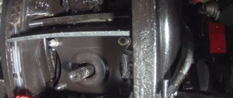
Features of the KrAZ gearbox
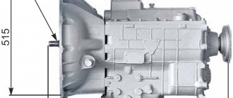
KrAZ gearbox - appearance
The manual gearbox found on KrAZ is supplemented with fixed shaft axles. It provides silent switching of speed modes. Constant mesh gears are distinguished by their operating efficiency.
The KrAZ checkpoint diagram displays the presence of the following individual elements:
- crankcase;
- box cover;
- switching mechanism;
- power take-off gear;
- synchronizer spline bushing;
- oil pump;
- shafts, etc.
KrAZ gearbox - diagram
The existing KrAZ gearbox housing is made of gray cast iron. This material is widely used in the field of mechanical engineering and effectively absorbs vibration vibrations. The crankcase has a special hole through which it is possible to control the level of transmission fluid. The box control drive is remote. If it breaks down, gears will engage worse. It needs to be adjusted.
The KrAZ gearbox includes synchronizers that make it easier to activate speed modes. The hydropneumatic clutch actuator is characterized by fast response.
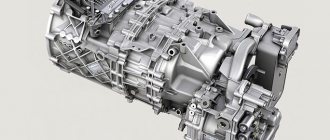
Gearbox YaMZ-238A - diagram
KrAZ may have a YaMZ-238B gearbox (4 gears), which is complemented by a range multiplier (8 forward gears and 2 reverse gears). This type of transmission makes it easier to drive the car. The YaMZ-238B gearbox has a dry double-disc clutch. Thanks to the divider, gentle operation of the automotive system is ensured. It also reduces the need for the driver to change gears frequently.
Possible breakdowns in the transmission system
KrAZ is a machine with a reliable technical part. Its maintenance consists of periodically inspecting fasteners, checking the level and quality of the oil. On a cold engine, the fluid should reach the control hole in the KrAZ gearbox housing.
Gearbox malfunctions on KrAZ appear as a result of wear and tear of the component parts of this unit. As a rule, this causes extraneous noise in the operation of the box and makes it difficult to switch on the gears. In this case, it is mandatory to check the oil level in the gearbox. Difficulty shifting gears may be due to incomplete disengagement of the clutch. It needs adjustment.
The KrAZ gearbox is equipped with needle bearings, when worn, extraneous noise occurs, usually at idle. To replace them, the gearbox must be removed from its seat.
Transfer case characteristics
The KrAZ vehicle is equipped with a transfer case (TC), which is mechanical and two-stage. It is necessary to distribute the moment of force along the axes of the vehicle. Also, the transfer case has a power take-off shaft.
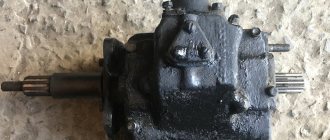
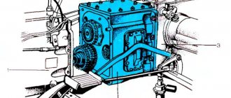
Transfer case for KrAZ - diagram
It should be noted that there is a drum-type hand brake. The KrAZ transfer case has a gear-type oil pump. From it, transmission fluid flows through channels to the rubbing surfaces of the intermediate shaft.
On KrAZ, the transfer case is located behind the gearbox and is connected by a driveshaft. The RK shafts are assembled in a crankcase, which is equipped with a special cover. The bearings have ball and roller shapes. If there is a problem with the operation of this device, it must be disassembled on a special stand.
The KrAZ power take-off reduces fuel consumption, facilitates changing gears, and helps prolong the functioning of the clutch and engine.
The power take-off box performs the same functions as the RK. This includes the crankcase, shafts with gears and bearings. It is made of reliable materials. The shafts are designed for heavy loads.
The cardan transmission includes several shafts. It unites not only the RK and the KrAZ checkpoint, but also the drive axles.
Description of the gearbox switching diagram on KamAZ: photo and video
The Kamaz gear shift pattern is directly dependent on the installed gearbox on the vehicle. But sometimes, even with full knowledge of all the theoretical data in controlling the Kamaz gearbox, it is very difficult to immediately navigate how to use and change gears.
In this article we will explain in detail how the gearbox works and what its structure is.
How does the checkpoint work?
Remember that you need to change the desired gears only with the clutch completely disengaged (off). For example, to shift from top gear B to lower gear H (or vice versa), lower or raise the gearshift switch (depending on the situation), squeeze the clutch, wait about 1 second and release, and only now it will turn on.
Advice: the clutch pedal must be moved sharply and depressed only to the end. You need to choose the moment when it is best to switch the required gears based on the tachometer readings.
Some tips for using the Kamaz box. By following these tips, your engine will always run in economical mode.
What is the structure of the checkpoint
Basically, two types of gearboxes are installed on KamAZ: 5-speed (model 14) and 10-speed (model 15). The first type is installed on single Kamaz vehicles, and the second type box is more suitable for use in road trains. In addition, the 10-speed consists of a regular 5-speed. Plus, equipped with a reducer-divider. The structure of the divider gearbox allows (of course, in combination with a 5-speed gearbox) to control ten forward gears and two reverse gears.
Advantages of boxes equipped with a divider:
For Kamaz vehicles with heavy load capacity, the previous boxes were modernized. And a new model of gearbox 152 was released. How is it different?
In the new model, the divider is controlled by a pneumatic system. Only a professional and a service station employee can service such a system. Since this procedure requires certain skills and knowledge.
Video “Checkpoint on a Kamaz vehicle”
You will be able to view how to switch the gearbox in a KamAZ in full detail.
KrAZ-260 - Wikipedia
Material from Wikipedia - the free encyclopedia.
Unverified version
(what to do?) Skip to navigation Skip to search
| KrAZ-260 | |
| KrAZ-260 | |
| Batkivska company | AvtoKrAZ |
| Rocks of Virobnitstva | 1979-1993 |
| Mіstse virobnitstva | URSR, Kremenchuk Ukraine, Kremenchuk |
| Front(s) | KrAZ-255B |
| Advancer(s) | KrAZ-6322 |
| Wheelbase | 4600+1400 mm |
| Dovzhina | 9030 mm |
| Width | 2720 mm |
| Height | 2985 (with awning 3115) mm |
| Clearance | 370 mm |
| Anterior track | 2160 mm |
| Posterior track | 2160 mm |
| Vaga | 12775 kg |
| Best quality | 80 km/year |
| Baku locality | 2×165+50 l |
| Controversial | TO |
uk.wikipedia.org
KAMAZ gear shift diagram
The KAMAZ gear shift diagram is clear from the figure. Here B is the highest gear. H – low gear. Numbers from 1 to 5 indicate gears in the main gearbox. 3- activation of KAMAZ reverse gear.
However, it is not enough to know the Kamaz gear shift pattern. It is also necessary to operate it correctly in order to ensure a long life and reduce fuel consumption. First of all, do not exceed the weight of the vehicle with cargo, which is indicated in the passport for the vehicle. Start moving the car smoothly, shift gears confidently, effortlessly, disengaging the clutch. When changing from one gear to another, pause briefly when the lever is in neutral. Shift into gears on time, exactly when the speed increases to the maximum for this gear.
As can be seen from the KAMAZ gear shift diagram, reverse gear is down to the left. It only needs to be turned on when the car has come to a complete stop.
While driving, it is necessary to remove your foot from the clutch pedal, as this is true, although it quietly leads to damage to the clutch parts. If the load has increased, for example on a hill, and the speed drops below 1200, you need to switch to a lower gear. If, on the contrary, there is a descent ahead, then you need to take your foot off the gas pedal, due to inertia the car will move further, but by reducing the speed, you will save on fuel and the wear of all KAMAZ mechanisms will be reduced. And never forget to maintain the pressure in your car tires within the limits specified by the manufacturer.
Source
Not available:
| № | Part code | Name | Quantity per model, pcs. |
| 120-1702159 | Control lever handle | 4 | Not available |
| 200-3504055-B2 | Right traction fork | 8 | Not available |
| 200-3508045-02 | Traction fork | 3 | Not available |
| 200319-P29 | Bolt M10x1.5x50 | 1 | Not available |
| 201468-P29 | Bolt M8x1.25x50 | 4 | Not available |
| 201509-P29 | Bolt M10x60 | 2 | Not available |
| 214-1804019-A | Bracket right | 1 | Not available |
| 214-1804020-A1 | Left bracket | 1 | Not available |
| 214-1804048 | Intermediate lever | 1 | Not available |
| 214-1804050 | bracket | 2 | Not available |
| 214-1804063 | Switching rod for transfer case and front center differential assembly | 2 | Not available |
| 214-1804065 | Rear transfer case engagement rod assembly | 1 | Not available |
| 214-1804068 | Rear differential clutch engagement rod assembly | 1 | Not available |
| 214-1804069 | Traction | 2 | Not available |
| 214-1804074 | Traction | 1 | Not available |
| 214-1804106-01 | Left intermediate lever | 1 | Not available |
| 214-1804125-A | Traction | 1 | Not available |
| 214B-1804046 | Intermediate lever with oiler assembly | 1 | Not available |
| 220V-8606026 | Additional lever | 1 | Not available |
| 220V-8606048 | Intermediate roller | 1 | Not available |
| 220V-8606050-B | bracket | 1 | Not available |
| 220V-8606052-01 | Upper lever | 1 | Not available |
| 220V-8606054 | Pull eye | 1 | Not available |
| 221-1804110-A1 | Intermediate lever roller | 1 | Not available |
| 222-1804035 | Roller | 1 | Not available |
| 222-1804062 | Roller | 1 | Not available |
| 222-8606028-02 | Front link assembly | 1 | Not available |
| 222-8606053-01 | Lower lever | 1 | Not available |
| 222-8606056-02 | Rear link assembly | 1 | Not available |
| 222B-1804100 | Intermediate lever right | 1 | Not available |
| 250615-P29 | Nut M12x1.25 | 4 | Not available |
| 250868-P29 | Nut M10x1 | 1 | Not available |
| 255B-1804037-01 | Lever block | 1 | Not available |
| 255B-1804051 | Front axle engagement lever | 1 | Not available |
| 255B-4202180 | Lever arm | 1 | Not available |
| 256-8606062-01 | Traction fork | 1 | Not available |
| 256B-8606015 | Lever arm | 1 | Not available |
| 256B1-8606029 | Traction | 1 | Not available |
| 256B1-8606057 | Traction | 1 | Not available |
| 258040-P29 | Cotter pin 3.2x25 | 1 | Not available |
| 258052-P29 | Cotter pin 3.6x20 | 9 | Not available |
| 258069-P29 | Cotter pin 5x36 | 1 | Not available |
| 260058-P29 | Finger | 4 | Not available |
| 260088-P29 | Finger | 9 | Not available |
| 264020-P8 | Grease nipple 1/8″ | 3 | Not available |
| 264030-P8 | Grease fitting | 4 | Not available |
| 264040-P8 | Grease nipple 1/8″ | 1 | Not available |
| 345020-P29 | Washer | 1 | Not available |
| 347001-P | Segment key 6x9 | 4 | Not available |
| 347013-P | Key | Not available |
Can’t find the required part from the group Control of the transfer case and tipping mechanism of the KrAZ-256B1 vehicle on the KrAZ-256 ? Consult our specialists by phone 8-800-700-19-88 or by email. We will definitely help you!
User manual
The manual supplied with the vehicle contains the following recommendations:
- Starting the engine is only permitted with the gearbox lever in neutral.
- Use diesel fuel or T1 aviation kerosene for the preheater.
- When operating the winch, follow safety regulations.
- It is forbidden to start driving a car with a faulty brake system.
- It is not recommended to reduce tire pressure that has increased due to heating of the components while driving.
- It is prohibited to engage differential locks on paved roads.
- Switch speeds in the transfer gearbox and engage the locks only when the vehicle is stationary.
- When parked for a long time, disconnect the batteries from the on-board network.
Spare parts for Ural, Kraz, MAZ, Kamaz trucks. Engine parts YaMZ-236, YaMZ-238
__________________________________________________________________________
__________________________________________________________________________
Gearbox for KRAZ-255, KRAZ-260 vehicles
___________________________________________________________________________
Disassembling the KRAZ-255, KRAZ-260 gearbox The KRAZ-255, KRAZ-260 gearbox is disassembled on a stand, and if it is not available, on a workbench 500-600 mm high. In most cases, to eliminate any malfunction or replace individual parts, it is enough to disassemble the KRAZ gearbox into separate large units (box cover with shift mechanism, drive shaft unit, driven shaft units, etc.). Sequence of disassembling the KRAZ-255, KRAZ-260 gearbox
Fig.7-9. Gearbox KRAZ-255, KRAZ-260 1 — drive shaft; 2, 18, 25, 35 — bearings; 3—lubricant supply hose; 4 — gear shift lever; 5 — fork rod head; 6 — locking ball spring; 7 — fork for fourth and fifth gears; 8 — synchronizer for fourth and fifth gears; 9—thrust washer; 10—fifth gear gear of the driven shaft; 11 — gear of the third gear of the driven shaft; 12—fork for shifting second and third gears; 13 — synchronizer for second and third gears; K - gear of the second gear of the driven shaft; 15 — first gear and reverse forks; 16 — first gear and reverse gear of the driven shaft; 17 - cover; 19 — spacer sleeve;
20 - oil seal; 21 - flange; 22 - driven shaft; 23 — thrust washer; 24 - cover; 26 — retaining ring; 27 — intermediate shaft; 28 — gear of the second gear of the intermediate shaft; 29 — spacer sleeve; 30 — third gear of the intermediate shaft; 31 — fifth gear of the intermediate shaft; 32—power take-off gear; 33 — constant mesh gear of the intermediate shaft; 34 — lock ring; 36 — oil pump drive gear; 37 — driven gear of the oil pump: 38 — oil pump; 39 — drive shaft bearing cover; 40 — clutch release fork; 41 — clutch release; 42 - cap nut; 43 — fuse spring; 44 — axis of the reverse gear block; 45—gear block; 46 — intermediate sleeve; 47 - needle bearing
Remove the rear support bracket for the KRAZ-255, KRAZ-260 gearboxes. Carefully remove the gearbox cover without damaging the gasket. Disconnect the clutch release spring from the clutch and bracket, unscrew hose 3 (Fig. 7-9) to lubricate the clutch and tie the free end of the hose with wire to one of the holes in the clutch housing. Remove clutch release clutch 41. Unscrew the nut of the clutch release fork pinch bolt and remove the pinch bolt. Turn the yoke shaft 180° and slide the yoke 40 along the shaft so that the segment key can be removed. Having knocked out the segment key, remove the shaft, while simultaneously removing the clutch release fork from the shaft. Using a universal puller, remove flange 21 from the driven shaft. Using puller bolts, remove cover 39 from the drive shaft and the cover gasket. Lightly hitting drive shaft 1 with a hammer and rocking it with your hand, remove the drive shaft assembly with bearing from the crankcase socket. Remove cover 17 of the rear bearing of the driven shaft of the KRAZ-255, KRAZ-260 gearbox (while being careful not to damage the sealing gasket). Remove the gasket and spacer sleeve 19. Press out the rear bearing of the driven shaft, having first removed the retaining ring from it. Using wire grips, remove driven shaft 22 assembled with gears from the KRAZ-255, KRAZ-260 gearbox housing. Carefully remove the cover 24 of the rear intermediate shaft bearing so as not to damage the gasket. Remove the gasket. Remove thrust washer 23 of the intermediate shaft. Then remove the rear bearing of the intermediate shaft, having first removed the retaining ring 26 from it. Using wire grips, remove the intermediate shaft 27 from the gearbox housing. Remove oil pump 38 and pump gasket. Remove the axle of the reverse gear block from the crankcase, then remove gear block 45, bearings 47 and intermediate sleeve 46 from the crankcase. The drive shaft of the KRAZ-255, KRAZ-260 gearbox should be disassembled in the following sequence: - clamp the drive shaft in a vice and bend the tendril lock washer; — unscrew the ring nut and remove the lock washer; - compress the bearing. The driven shaft of the KRAZ-255, KRAZ-260 gearbox should be disassembled in the following sequence: - remove gear 16 of the first gear and reverse gear, synchronizer 8 of the fourth and fifth gears from the splines; — using a screwdriver and special hooks, remove the locking ring and thrust washer 9 of the fifth gear gear; — install the driven shaft of the KRAZ gearbox on a press, place wooden pads under gear 14 of the second gear and, pressing with a press through a wooden spacer or a special mandrel, compress the gear bushings and the splined bushing of the second and third gear synchronizer. Remove the fifth gear gear 10, the fifth gear bearing needles, the intermediate bearing ring, the fifth gear bearing sleeve, the third gear, the third gear bearing needles 18, the intermediate bearing ring, the third gear bearing sleeve, the second and third synchronizer 13 from the shaft. gear, synchronizer spline bushing, second gear gear 14, second gear bearing needle 35, intermediate bearing ring and second gear thrust washer. Disassemble the KRAZ gear shift mechanism in the following sequence: - unscrew the nuts of the studs securing the shift lever support, remove the support and its gasket, then remove springs 6 and locking balls of the shift mechanism from the cover; - clamp the support with the shift lever in a vice, unscrew the shift lever handle and, pressing on the washer, compress the gear shift lever spring so that the washer pin is released. — Use pliers to pull out the washer pin, remove the washer, lever spring, support cover and cover O-ring. — Knock out the shift lever mounting pin from the support and remove the KRAZ gearbox lever; bend the antennae of the lock washer, unscrew the cap nut 42, unscrew the nut of the first gear and reverse gear fuse, remove the fuse, fuse spring 43, the first gear and reverse gear shift lever and its axle; - Unscrew the set screws of the rod heads and shift forks, remove the plugs of the rod holes, use a drift to knock the rods out of the cover, remove forks 7, 12 and 15 and heads 5, remove the balls and rod lock pin. Disassemble the intermediate shaft of the KRAZ-255, KRAZ-260 gearbox in the following sequence: - remove the oil deflector washer and, using two screwdrivers, remove the locking ring 34; — install the intermediate shaft 27 on the press, compress the constant mesh gear 33 and remove the gear key. — After this, alternately compress gears 32, 31, 30 and 28, first removing the segment keys of the already removed gears. Disassemble the oil pump in the following sequence: - using pliers, remove the drive gear 36 from the oil pump housing assembled with the axle; press the gear off the axle and remove the key; — remove the driven gear 37 and its axis from the pump housing; — Unscrew the valve spring plug, remove the spring and valve ball from the pump body. Wear of the drive shaft splines is allowed up to 5.7 mm (nominal size 5.9+0'05 mm). Wrinkling or twisting of splines is not allowed. Wear of the splines of the driven shaft of the KRAZ gearbox is allowed within 0.12–0.16 mm. Wear of the gear shift fork cheeks in thickness is allowed up to 10 mm. The cheeks should lie in the same plane and be perpendicular to the axis of the hole with an accuracy of 0.2 mm. Wear of the teeth of the synchronizer carriage (along the length) on the switching side is allowed up to a tooth size of 8 mm. Wear of the synchronizer splines of the KRAZ-255, KRAZ-260 second and third gears (in thickness) is allowed up to a size of 6.25 mm when measured at a distance of 2.35 mm from the top. Wear of the spline hole of the fourth and fifth gear synchronizer (along the internal diameter) is allowed up to 50.127 mm, the development of the cavity in width is up to 14.2 mm. When determining the degree of wear of the bronze cone rings of the synchronizer cages, the conical surfaces of the corresponding shafts and gears mating with them are used. When placing a ring or gear on the shaft, measure the gap between the end of the tooth and the synchronizer cage of the KRAZ-255, KRAZ-260 gearbox. The wear of the cone ring is considered within acceptable limits if the gap between the end of the tooth and the holder is at least 1.5 mm. Wear of the synchronizer coupling groove under the fork is allowed up to a size of 11.76 mm. When the coupling on the synchronizer carriage is loosened, the unusable pins are drilled out, new ones are installed and sealed with brass. The soldering area is cleaned. Wear of the splines of the propeller shaft mounting flange (widthwise) is allowed up to a size of 9.2 mm, wear of the journal for the oil seal is allowed up to a diameter of 69.6 mm. It is allowed to wear the lower ball end of the KRAZ-255, KRAZ-260 gear shift lever to a size of 18.65 mm; wear of the spherical surface of the upper ball stop to a size of 35.2 mm: wear of the hole in the upper ball stop for the pin (width) to a size of 10.6 mm. Assembling the KRAZ-255, KRAZ-2 60 gearbox First, large gearbox components are assembled, and then the gearbox itself is assembled from sub-assembled components. Assembling the drive shaft of the KRAZ gearbox If for some reason a new drive shaft or a new synchronizer for the fourth and fifth gears is installed in the KRAZ-255, KRAZ-260 gearbox, then before assembly the conical surface of the synchronizer ring should be ground to the conical surface of the synchronizer for the fourth and fifth gears. The area of the contact marks must be at least 65% of the surface of the ring cone and be distributed evenly over the entire cone surface. The sequence of assembling the KRAZ drive shaft: - press ball bearing 2 assembled with a retaining ring onto the drive shaft 1 (see Fig. 7-9) until it stops; — clamp the drive shaft of the drive shaft of the KRAZ gearbox in a vice, install the lock washer, screw in and tighten the ring nut using a wrench, and then bend the lock washer's tendril. The rotation of the outer race of the bearing must be free, without jamming. Assembling the driven shaft of the KRAZ-255, KRAZ-260 gearbox When assembling the driven shaft of the KRAZ-255, KRAZ-260 gearbox, in case of replacing the synchronizer or gear, except for the first gear and reverse gear, the conical surfaces of the synchronizers should be ground to the conical surfaces of the gears. If a new needle bearing for a gear is installed on the driven shaft, then it is assembled from needles of one group (the diameter of the bearing needle of the first group is 3,000-2,995 mm, the second group is 2,995-2,990 mm). Assembly sequence of the driven shaft KRAZ-255, KRAZ-260: Install a thrust washer and an intermediate ring on the driven shaft 22, assemble the needle bearing. To facilitate assembly, it is possible to install bearing needles on solid oil. Then install gear 14 of the second gear and press in the spacer sleeve for the synchronizer of the second and third gears until it stops. The spacer sleeve with its annular cut should face the front end of the driven shaft. Install synchronizer 13 of the second and third gears onto the spacer sleeve, with the short end of the synchronizer carriage facing the second gear gear. The synchronizer carriage of the KRAZ-255, KRAZ-260 gearbox must move freely, without jamming, along the splines of the spacer sleeve. Press in the bushing of third gear gear 10 until it stops. Assemble the needle bearing, then install gear 11. Press the bushing of fifth gear gear 10 until it stops. Assemble the needle bearing of fifth gear gear 10, install fifth gear gear 10, thrust washer 9 and locking ring. The gap between the ends of the thrust washer and the bearing bushing is set within 0.10-0.15 mm. The gap size is adjusted by selecting a thrust washer before installing the fifth gear gear. All gears of the driven shaft of the KRAZ-255, KRAZ-260 gearboxes must rotate freely, without jamming. The cage of the cone rings of the synchronizer of the second and third gears must have longitudinal movement within the range of 3-5 mm. The engagement of the teeth of the synchronizer carriage with the teeth of the gears must be free, without jamming. Install synchronizer 8 of the fourth and fifth gears so that the annular groove of the carriage and synchronizer is facing the fifth gear gear. The movement of the KRAZ-255, KRAZ-260 gearbox synchronizer along the splines must be free, without jamming. Install gear 16 of first gear and reverse gear so that the recess under the shift fork faces gear 14. The gear moves along the splines freely, without jamming. Assembly of the intermediate shaft of the KRAZ-255, KRAZ-260 gearbox The constant mesh gear 33 is installed with the elongated side of the hub towards the rear end of the intermediate shaft, and the remaining gears with the elongated side of the hub are installed towards the front end.
Rice. 10. Gearshift mechanism of the KRAZ-255, KRAZ-260 gearbox 1 — lever support cover; 2 — shift lever spring; 3 — shift lever spring washer; 4— gear shift lever; 5 — shift lever for first gear and reverse; 6 — axis of the first gear shift and reverse gear; 7— fuse spring for engaging first gear and reverse gear; 8 - fuse for first gear and reverse; 9 — sealing ring of the support cover; 10 — gear shift lever support; 11 — lever mounting pin; 12— washer; 13 — nut of the fuse for engaging first gear and reverse gear; 14 - cap nut; 15 — locking ball spring; 16 — locking ball of the gear shift mechanism; 17 — lever spring washer pin; 18— stud for fastening the gear shift lever support; 19—oil filler plug of the gearbox; 20 — retaining balls; 21 — gear shift fork rod lock pin; 22 — plug for the upper cover of the gearbox; 23—fork for shifting first gear and reverse; 24 — fork for shifting second and third gears; 25 — gear shift fork set screw; 26 — fork for shifting fourth and fifth gears; 27 — head of the fork rod for shifting the second and third gears, 28 — head of the rod for shifting the first gear and reverse gear; 29 — plug for the upper cover of the gearbox; 30 — rod for shifting the first gear and reverse gear, 31 — rod for shifting the second and third gears; 32 — fork rod for shifting fourth and fifth gears; 33— upper cover of the gearbox; 34 — gasket The upper cover of the KRAZ-255, KRAZ-260 gearbox must be assembled in the following order. Install rod 30 (Fig. 10) of the first gear and reverse gear shift forks into the box cover. Place head 28 and shift fork 23 onto the rod. Move the rod to the neutral position, insert two locking balls 20 of the lock through the hole under the rod of the second and third gears. Insert rod 31 of the second and third gear shift fork. Place head 27 and shift fork 24 onto the rod. Insert lock pin 21 into the hole in the rod. Move the rod to the neutral position. Rod 32 of the fourth and fifth gear forks of the KRAZ gearbox is installed in the same way. The rods installed in the cover must move freely by hand. Secure the switching heads and forks with screws 25. Rocking of the forks and heads on the rods is not allowed. Seal the set screws with tie wire. Check the operation of the rod lock. When one of the rods moves longitudinally, the other two must be locked with a lock in the neutral position. Place spring 7 on the fuse 8 of the first gear and reverse gear. Insert the fuse with the spring into the driver axle 6, screw the nut 13 onto the fuse. Place the driver 5 of the first gear and reverse gear of the KRAZ gearbox onto the axle, insert the driver with the axle into support 10. Shift guide first gear and reverse gear should rotate freely on the axle without jamming. Clamp the support in a vice, install lever 4 into it and, with light blows of a hammer, hammer in pin 11 securing the lever. Install o-ring 9 and cover 1 onto the support through the lever. Then put spring 2 and washer 3 on the lever. Pressing on the washer, compress the spring and insert pin 17 of the spring washer into the hole in the lever. Screw the handle onto the lever. Adjust the gap (within 1.5-2.0 mm) between the switching head of the lever and the protrusions of the driver using the fuse nut 13. After adjustment, tighten the nut, put lock washer 12 on the end of the axle, screw on cap nut 14 and bend the lock washer antennae (one on the support, the other on the edge of the cap nut). Insert balls 16 and springs 15 into the holes of the cover, install the gasket and shift lever support on the cover. Tighten the nuts of studs 18 securing the support, placing spring washers under the nuts. Assembling the KRAZ-255, KRAZ-260 gearbox oil pump After assembly, check the distance from the end of the drive gear to the shaft shoulder, which should be within 13.5-14.5 mm. In addition, check the radial clearance (on one side) between the wall of the housing socket and the gear. The gap is allowed within 0.11-0.20 mm. The KRAZ-255, KRAZ-260 gearbox is finally assembled in the following sequence: Install the assembled intermediate shaft of the KRAZ-255, KRAZ-260 gearbox into the gearbox housing. Press ball bearing 25 (see Fig. 7-9) with retaining ring 26 onto the rear end of the intermediate shaft and fasten thrust washer 23. Seal the bolts together with tie wire. Install the reverse gear block 45 assembled with roller bearings 47 and intermediate sleeve 46 into the crankcase, then insert the block axle 44. The rotation of the KRAZ-255, KRAZ-260 gearbox gear block on the axle should be free, without jamming. The longitudinal movement of the block on the axis should be in the range of 0.15–0.71 mm. It is allowed to install washers to compensate for wear of the gearbox housing bosses. Install oil pump 38. Seal the fastening bolts with tie wire. Install a cardboard gasket 0.25–0.35 mm thick between the pump housing and the crankcase plane. Install the driven shaft of the KRAZ-255, KRAZ-260 gearbox into the crankcase, press ball bearing 18 with a retaining ring all the way onto the rear end of the shaft and install spacer sleeve 19, and install a roller bearing on the front end of the shaft. Install the drive shaft into the crankcase. Install the bearing cover 39 using a brass mandrel with a polished surface 1. Install the bearing covers of the driven 17 (see Fig. 7-9) and intermediate shaft 27, placing gaskets under the covers. Install the propeller shaft mounting flange 21 and a flat washer onto the rear end of the driven shaft. Secure the flange with a nut and secure it with a cotter pin. Secure the bolts securing the drive shaft bearing cover, clutch housing and oil pump using tie wire in pairs. All shafts of the KRAZ-255, KRAZ-260 gearbox should rotate easily. If there was a need to replace the oil seal of the drive or driven shaft, then the oil seal is pressed into the cover using a special mandrel. Insert the clutch release fork shaft into the holes in the crankcase, while simultaneously putting the fork on the shaft. Install a segment key in the groove of the shaft and slide the shutdown fork onto the key. Then secure the fork to the shaft using a coupling bolt and a spring washer. Install the clutch release clutch onto the bearing cover. Attach the release spring to the coupling and bracket and screw the lubrication hose to the coupling. Set the synchronizers, first gear and reverse gears and the forks of the KRAZ-255, KRAZ-260 gearbox cover rods to the neutral position. Place the cover on the crankcase, place a gasket under it and secure it. Check the gear shift, it should be free, without jamming. Attach the rear support bracket of the power unit to the crankcase with bolts and spring washers.
_________________________________________________________________________
_________________________________________________________________________
_________________________________________________________________________
- Cardan shafts and power take-off Ural-4320
- Transmission gearbox Ural-4320
- Bridges Ural-4320
- Transfer case Ural-4320
- Steering Ural-4320
- Truck cranes and cranes based on trucks
_________________________________________________________________________
_________________________________________________________________________
- Cylinder block and cylinder head YaMZ-236 HE2, YaMZ-236 BE2
- Checking and adjusting YaMZ-236
- Power system and lubrication system YaMZ-236
- Driven and driven clutch discs YaMZ-236, 238
- Cooling and lubrication systems YaMZ-238
- Fuel injection pump YaMZ-238
_________________________________________________________________________
- Kamaz diesel engine
- Repair and adjustment of Kamaz power steering
- Kamaz-152 gearbox with divider
- Gearbox parts for Kamaz-5320 gearbox
- Kamaz transfer case and driveshafts
- Kamaz gearbox repair
- Clutch KamAZ-5320
- Construction of Kamaz-4310 drive axles
- Power steering MAZ-5551, 5549, 5335, 5336, 5337
- Front axle and steering rods MAZ-5551, 5549, 5335, 5336, 5337
- Clutch adjustment MAZ-5551, 5549, 5335, 5336, 5337
- Adjustment and repair of gearboxes MAZ-5551, 5549, 5335, 5336, 5337
- Repair and maintenance of the rear axle MAZ-5551, 5549, 5335, 5336, 5337
- Front axle parts and steering rods MAZ-5516, 5440
- Steering Maz-5516, 5440
- Details of driving axles Maz-5516, 5440
- Clutch device ZIL-130
- Repair of ZIL-130 gearbox
- Repair of rear axle ZIL-130
- Basic parts of the ZIL-130 engine
- Transfer case and power take-off ZIL-131
- Drive axles ZIL-131
- Steering ZIL-131
- Maintenance of ZIL-645 engine parts