Category: KAMAZ
- Design and features of KamAZ PSU
- Operating principle of CCGT
- Amplifiers used on KamAZ
- Malfunctions of KamAZ PGU
- Do-it-yourself KamAZ PSU repair
- Adjusting KamAZ PGU
The applied forces required for the truck's operating processes are proportional to the dimensions of the vehicle. KamAZ PGU reduces the load required for the functioning of the most important element in driving a vehicle, the clutch.
An uninitiated user is unlikely to appreciate the unit, because without an amplifier, the gear shift circuit and the operating condition of the car will not be affected. However, the direct participant in management knows the true price of the mechanism. With the absence of a PSU, driver fatigue increases and the maneuverability of the equipment decreases. As a result, road safety suffers and the number of accidents increases, which means human lives.
KamAZ-5490:
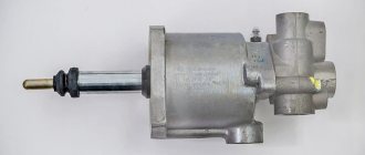
PGU device (pneumohydraulic clutch booster)
The pneumatic hydraulic booster of the clutch drive is used to reduce the force applied to the clutch pedal by the driver.
- hydraulic cylinder with piston, rod and spring;
- a pneumatic cylinder with a piston, a rod (common with the hydraulic cylinder piston) and a return spring;
- a follower mechanism consisting of a follower piston with a cuff, a diaphragm (sandwiched between two parts of the housing), in the center of which the exhaust valve seat is attached, a diaphragm return spring;
- exhaust and intake valves (mounted on one rod) with a return spring;
- intake valve seats;
- a hole closed with a seal to prevent dirt from entering, connecting the above-piston cavity of the pneumatic cylinder with the environment.
When the clutch is engaged, the common rod is pressed against the pistons of the hydraulic cylinder and pneumatic cylinder.
The piston of the follower mechanism occupies a position corresponding to the open exhaust valve connecting the above-piston space of the pneumatic cylinder with the environment and the closed inlet valve. When the clutch is disengaged, the working fluid from the master cylinder enters the hydraulic cylinder of the pneumatic hydraulic booster, and at the same time through the channel to the piston of the follower mechanism. Fluid pressure moves the piston toward the exhaust valve seat. The diaphragm, bending, moves the seat to the exhaust valve, which sits in the seat, isolating the above-piston space of the pneumatic cylinder from the environment.
Next, the force from the exhaust valve is transmitted through the rod to the intake valve, which opens, and the compressed air flows through the channel into the above-piston space of the pneumatic cylinder. The piston of the pneumatic cylinder, mixing, acts on the piston rod of the hydraulic cylinder. The piston transmits force to the pusher, which acts on the clutch release fork lever. Part of the compressed air enters the diaphragm cavity.
Thus, the follower piston is under the action of two oppositely directed forces: the action of the working fluid on one side and the compressed air on the other. The pistons of the follower mechanism and the pneumatic cylinder are selected to ensure the necessary reduction in the force on the clutch pedal.
When the clutch pedal is released, the pressure of the working fluid drops, and all parts return to their original position under the action of return springs; the above-piston space of the pneumatic cylinder communicates with the environment through the open exhaust valve.
If the pneumatic system fails, the hydraulic cylinder piston moves only under the pressure of the working fluid.
The operating principle of the unit.
The CCGT is mounted on the cabin panel. The clutch accelerator is connected to the unit via a pusher. When the clutch is disengaged, the rod is pressed against the piston of the pneumatic cylinder. When you press the accelerator, fluid flows through the channel into the amplifier. The movement of the pusher opens the valve of the pneumatic system. When the required pressure is reached, the inlet valve opens completely and air enters the pneumatic cylinder chamber. The piston together with the clutch release pusher reaches the top point. A special feature of the piston operation is the effect of two forces on it. On the one hand, it is exerted by the pressure of the compressed air of the pneumatic system, on the other, by the action of the working fluid of the hydraulic booster. The systems are designed to provide maximum comfort for the driver to operate the clutch mechanism. When the pedal is released, the pressure of the hydraulic booster fluid decreases and the pneumatic cylinder stops its operation. The exhaust valve opens and the air escapes to the atmosphere. If the unit breaks down, the clutch is disengaged only through the operation of the hydraulic booster.
Pneumatic system design.
The mechanism consists of a tank mounted on a frame, a single safety valve and lines. The air supply to the amplifier is carried out through a separate circuit of the system. The valve is located on the reservoir and separates the air lines leading to the clutch mechanism and other components. There is a tap to drain the condensate formed in the cylinders.
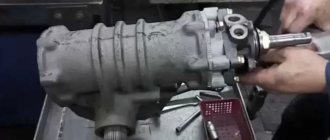
PGU device.
The amplifier consists of a housing, inside of which there is a piston and a pusher. The piston has a cuff and moves in the axial direction. The amplifier housing is closed on top with a lid through which the pusher passes. To protect against dirt and dust, a wiper is installed in the mechanism on the amplifier cover. The pusher is connected to the clutch release accelerator by a fork mechanism. The accelerator is installed on the axis of the bracket. Air is supplied to the unit from cylinders through the operation of a valve mechanism.
Main malfunctions of the mechanism.
Ural 5557 PGU and hydraulic booster fail for the following reasons:
- Swelling of the sealing ring.
- Incorrect adjustment of the mechanism.
- Wear of cuffs and other elements.
- Release cylinder fork bend
- Fork axle wear.
- Pedal failure.
- Drive jammed.
- Valve wear.
If the mechanism jams, it is worth disassembling it and rinsing it in gasoline or kerosene. Wear of sealing rings and valves leads to leakage of compressed air from the cylinders. This problem can be noticed by the constant “hissing” of the unit. If the problems of the clutch PSU are not corrected in a timely manner, breakdowns of the hydraulic booster may occur in the future, which will lead to a stop in the operation of the vehicle and the need to install new spare parts from the Ural plant.
In what cases is it necessary to replace the unit?
Intensive use of the vehicle in urban conditions, where acceleration and braking often occurs, entails rapid wear of the transmission mechanisms. Frequently pressing the clutch accelerator entails wear on the amplifier itself. Ultimately, when the mechanism wears out, the smoothness of starting and shifting gears significantly deteriorates. In addition, sharp vibrations are transmitted from the engine through the transmission to the car frame. The PSU solves many problems, so its malfunction entails loss of comfort in controlling the mechanism and the vehicle as a whole.
Clutch URAL 4320
Adjusting the clutch pedal.
One of the problems with the operation of the amplifier is incorrect installation of the accelerator. To fix the problem, adjustments must be made. It is carried out in several stages:
Cylinder Ural 4320
- Bleed the air from the cylinders.
- Move the pneumatic cylinder to the upper position and fix it.
- Press the clutch accelerator to the floor.
- Adjust free play.
- Measure the stroke of the pusher with the engine running.
KamAZ-5320, PGU: design and principle of operation
What is the KamAZ-5320 PGU device? This question interests many beginners. This abbreviation may confuse an ignorant person. In fact, the PGU is a pneumatic hydraulic power steering. Let's look at the features of this device, its operating principle and types of maintenance, including repairs.
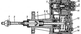
- 1 – spherical nut with lock nut.
- 2 – piston pusher of the clutch deactivator.
- 3 – protective cover.
- 4 – clutch release piston.
- 5 – back part of the frame.
- 6 – complex seal.
- 7 – follower piston.
- 8 – bypass valve with cap.
- 9 – diaphragm.
- 10 – inlet valve.
- 11 – graduation analogue.
- 12 – pneumatic type piston.
- 13 – drain plug (for condensate).
- 14 – front part of the body.
- “A” – supply of working fluid.
- “B” – supply of compressed air.
Bleeding and adjustment of PGU and GUR on KamAZ trucks
KamAZ PGU is a device designed to reduce the level of pressure exerted by the driver on the clutch pedal.
PGU - hydraulic power steering of a KamAZ pneumatic clutch type.
Design and principle of operation
The PGU device includes:
- spherical type nut;
- lock nut;
- a piston pusher that deactivates the clutch system;
- a cover that protects against damage;
- piston;
- complex type seal;
- bypass and inlet valve;
- cork;
- fuel fluid supply;
- system for compressing air flow.
The diagram also includes the following elements:
- spring mechanism;
- gearbox;
- diaphragm seats.
The operating principle of the PSU is as follows:
- The driver presses the clutch pedal.
- Under the pressure of the fuel fluid, the rod and piston part of the mechanism are activated.
- Movement occurs until the intake valve opens.
- The air flow moves in the direction of the pneumatic piston.
- The fork is retracted and the clutch system is disengaged.
Purpose and device
A truck is a fairly massive and large-sized vehicle. Controlling it requires remarkable physical strength and endurance. The KamAZ-5320 PGU device makes it easier to adjust the vehicle. This is a small but useful device. It makes it possible not only to simplify the driver’s work, but also increases work productivity.
The node in question consists of the following elements:
- Piston pusher and adjusting nut.
- Pneumatic and hydraulic piston.
- Spring mechanism, gearbox with cover and valve.
- Diaphragm seats, control screw.
- Bypass valve and piston follower.
Peculiarities
The amplifier housing system consists of two elements. The front part is made of aluminum, and the rear part is made of cast iron. A special gasket is provided between the parts, which acts as a seal and diaphragm. The follower mechanism automatically regulates the change in air pressure on the pneumatic piston. This device also includes a sealing collar, springs with diaphragms, as well as inlet and outlet valves.
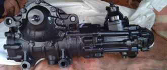
CCGT design
PGU or pneumohydraulic drive booster, consists of the following main parts:
- front and rear housings;
- protective casing;
- pistons (hydraulic with pusher, pneumatic);
- tracking mechanism;
- valves (bypass, inlet, outlet);
- reducer diaphragm;
- holes for supplying liquid and air.
The mounting location for the drive amplifier is on the right side of the clutch housing.
The front body of the device is usually made of cast iron, and the rear one is made of aluminum. Each has 2 bores into which pistons and a follower mechanism are installed. The housings are connected using bolts. The front one has a pneumatic piston sealed with a rubber cuff. A hydraulic piston, structurally manufactured together with a pusher, rests against its bottom (it is also called the “shutdown piston”). The cavity of the hydraulic piston is protected from the penetration of dust and dirt. The pusher is deflected from the axis at a certain angle for the correct functioning of the clutch drive amplifier.
Operating principle
When the clutch pedal is pressed under fluid pressure, the KamAZ-5320 PGU device presses on the rod and piston of the follower, after which the structure, together with the diaphragm, moves until the intake valve opens. The air mixture from the vehicle's pneumatic system is then supplied to the pneumatic piston. As a result, the forces of both elements are summed up, which allows you to retract the fork and disengage the clutch.
After the foot is removed from the clutch pedal, the pressure of the supply main fluid drops to zero. As a result, the load on the hydraulic pistons of the actuator and follower mechanism is reduced. For this reason, the hydraulic piston begins to move in the opposite direction, closing the inlet valve and blocking the flow of pressure from the receiver. The pressure spring, acting on the follower piston, moves it to its original position. The air initially reacting with the pneumatic piston is released into the atmosphere. The rod with both pistons returns to its initial position.
Production
The KamAZ-5320 PGU device is suitable for many model modifications of this manufacturer. Most old and new tractors, dump trucks, and military variants are equipped with pneumatic-hydraulic power steering. Modern modifications produced by various companies have the following designations:
- Spare parts for KamAZ (PGU) manufactured by KamAZ OJSC (catalog number 5320) with vertical placement of the tracking device. The device above the cylinder body is used on variations under the index 4310, 5320, 4318 and some others.
- WABCO. CCGT units under this brand are manufactured in the USA and are distinguished by their reliability and compact dimensions. This equipment is equipped with a system for monitoring the condition of the linings, the level of wear of which can be determined without dismantling the power unit. Most trucks with a 154 series transmission are equipped with this type of air-hydraulic equipment.
- Pneumatic hydraulic clutch booster "VABKO" for models with ZF type gearbox.
- Analogues produced at a plant in Ukraine (Volchansk) or Turkey (Yumak).
In terms of choosing an amplifier, experts recommend purchasing the same brand and model that was originally installed on the machine. This will ensure the most correct interaction between the amplifier and the clutch mechanism. Before changing the unit to a new variation, consult a specialist.
Amplifiers used on KamAZ
Structurally, KamAZ vehicles provide for the use of products of both domestic and foreign production. The operating principle of the mechanisms is identical; the devices differ in characteristics and design.
- Thus, the 5320 amplifier, produced at the Kama plant, structurally uses a vertical arrangement of the follower mechanism; the pneumatic cylinder is also installed vertically. Such devices are used on modifications: 5320, 4310, 43118, etc.
- The WABCO amplifier is manufactured in the United States of America. The product is distinguished by its compact size and lining wear indicators, which facilitates the use of the PGU. Similar devices are used on new KamAZ vehicle models: 5460, 6450, 6460, 65117, etc. The amplifier is compatible with “154” series gearboxes, which are used with power units that meet Euro-2 and Euro-3 standards.
- PGU "WABCO" for KamAZ modifications: 6460, 6520 and other equipment with ZF gearboxes.
- PGU "WABCO" for modifications of KamAZ: 4308, on which a ZF five-speed gearbox is installed.
- CCGT units made according to the “WABCO” type are produced in Ukraine and Turkey.
Service
To maintain the operating condition of the unit, carry out the following work:
- Visual inspection to detect visible air and fluid leaks.
- Tightening the fixing bolts.
- Adjust the free play of the pusher using a spherical nut.
- Adding working fluid to the system tank.
It is worth noting that when adjusting the KamAZ-5320 PGU of the Wabco modification, the wear of the clutch linings is easily visible on a special indicator extended under the influence of the piston.
Disassembly
This procedure, if necessary, is performed in the following order:
- The back of the body is clamped in a vice.
- The bolts are unscrewed. Remove the washers and cover.
- The valve is removed from the body part.
- The front frame is dismantled along with the pneumatic piston and its membrane.
- The following are removed: the diaphragm, the follower piston, the retaining ring, the clutch release element and the seal housing.
- The bypass valve mechanism and the hatch with the outlet seal are removed.
- The frame is removed from the yews.
- The thrust ring of the rear part of the housing is dismantled.
- The valve stem is freed from all cones, washers and seats.
- The follower piston is removed (you must first remove the stopper and other related elements).
- The pneumatic piston, cuff and retaining ring are removed from the front part of the housing.
- Then all parts are washed in gasoline (kerosene), sprayed with compressed air and go through the defect detection stage.
PGU KamAZ-5320: malfunctions
Most often, the following problems occur in the node in question:
- The compressed air flow is supplied in insufficient quantities or completely absent. The cause of the malfunction is swelling of the inlet valve of the pneumatic booster.
- Jamming of the follower piston on the pneumatic booster. Most likely, the reason lies in the deformation of the o-ring or cuff.
- There is a “failure” of the pedal, which does not allow the clutch to be completely disengaged. This problem indicates that air has entered the hydraulic drive.
Repair of KamAZ-5320 PGU
When troubleshooting the elements of a unit, special attention should be paid to the following points:
- Checking sealing parts. Deformations, swelling and cracks are not allowed on them. If the elasticity of the material is impaired, the element must be replaced.
- Condition of the working surfaces of the cylinders. The internal clearance of the cylinder diameter is monitored, which in fact must comply with the standard. There should be no dents or cracks on the parts.
The CCGT repair kit includes the following KamAZ spare parts:
- Protective cover for rear housing.
- Cone and diaphragm of the gearbox.
- Cuffs for pneumatic and follower piston.
- Bypass valve cap.
- Retaining and sealing rings.
Before installation, it is recommended to treat all parts with Litol type lubricant.
Replacement and installation
To replace the node in question, perform the following manipulations:
- The air is being bled from the KamAZ-5320 CCGT unit.
- The working fluid is drained or the drain is blocked using a plug.
- The clutch spring fork is removed.
- The water and air supply pipes are disconnected from the device.
- The fastening screws to the crankcase are unscrewed, after which the unit is dismantled.
After replacing deformed and unusable elements, the system is checked for leaks in the hydraulic and pneumatic parts. Assembly is carried out as follows:
- Align all the fixing holes with the sockets in the crankcase, after which the amplifier is secured using a pair of bolts with spring washers.
- The hydraulic hose and air line are connected.
- The release spring mechanism of the clutch release fork is mounted.
- Brake fluid is poured into the compensation reservoir, after which the hydraulic drive system is pumped.
- Re-check the tightness of the connections for leakage of working fluid.
- If necessary, adjust the size of the gap between the end part of the cover and the travel limiter of the gear divider activator.
Purpose and role of PSU in KAMAZ vehicles
In a number of old and all new models of KAMAZ trucks (military 4310, dump trucks 55111, 65115 and 6520, flatbed 43118 and 5320, tractors 5460 and 6460 and others), a pneumohydraulic booster (PGU) is integrated into the clutch drive system. This is due to the need to make the driver’s work easier, since the clutch in a truck has a large mass, and the springs develop a significant clamping force on the discs, and frequent disengagement leads to excessive fatigue.
The PSU greatly simplifies the task of disengaging the clutch, minimizing driver fatigue, while at the same time increasing safety (since in an emergency, disengaging the clutch will not require additional effort, and even at the end of the work shift the driver can easily do it) and improving the controllability of the truck.
It should be noted that in a number of KAMAZ models the PGU is simultaneously included in the control system of the gear divider (multiplier), which is installed between the clutch and the gearbox (most often it is an integral part of the gearbox). When changing gears, the divider must be turned off, which is ensured by the car's pneumatic system. The divider is switched off using a valve driven by the CCGT rod. Thus, when using a divider, it is turned off and on automatically simultaneously with the clutch being turned off and on when the pedal is pressed. Such a system is implemented on KAMAZ-5320 and many other models.
Schematic diagram of connection and placement of node elements
The operating principle of the KamAZ-5320 PGU is easier to understand by studying the diagram below with explanations.
- a – standard diagram of interaction of drive parts.
- b – location and fixation of node elements.
- 1 – clutch pedal.
- 2 – main cylinder.
- 3 – cylindrical part of the pneumatic amplifier.
- 4 – follower mechanism of the pneumatic part.
- 5 – air duct.
- 6 – main hydraulic cylinder.
- 7 – release clutch with bearing.
- 8 – lever.
- 9 – rod.
- 10 – drive hoses and pipes.
CCGT WABCO
STRUCTURE AND OPERATION OF PSU MADE
BY WABCO
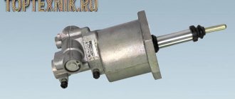
The clutch is released using a pneumohydraulic booster (PSU) from Wabco.
The PGU consists of 3 main parts: an actuator pneumatic cylinder, a servo system and a clutch lining wear indicator.
The CCGT structure is shown in Fig. 1.
Rice.
1. Pneumohydraulic booster (PGU) from Wabco:
1 - hydraulic housing; 2 — hydraulic piston; 3 — hydraulic cuff; 4 - wear indicator on the masonry; 5 — wear indicator washer; 6 — pointer body; 7.10—pressure spring; 8 — pneumatic piston; 9 — pneumatic cylinder; 11 — cover; 12 — rod; 13 — drainage tube. A - gap when the linings are worn; I - CCGT tracking system.
When you press the clutch pedal, the fluid pressure from the main cylinder is transmitted through pipelines to the pneumatic hydraulic booster, where it acts on the hydraulic piston 2 (Fig. 1) of the PSU and piston 1 (Fig. 2) of the follower device.
Under the action of the follower piston, pneumatic piston 2 moves (Fig. 2), which acts on the follower valve 5. The valve opens air access to the pneumatic cylinder 9 (Fig. 1) of the PSU, increasing the force effect of the PSU rod 12 on the clutch release fork. With the help of a tracking device, the air pressure entering the pneumatic cylinder of the PSU automatically changes, depending on the effort of the driver on the clutch pedal.
After the pedal stops working, the liquid pressure in the CCGT is released, the pneumatic valve of the tracking system is closed, and the pneumatic piston of the CCGT is set to its original state.
Using a pressure spring, piston 8 (Fig. 1) of the PSU with rod 12 is always connected without backlash to the clutch fork, clutch, diaphragm spring, and clutch pressure plate. When the clutch linings are worn, a backlash-free connection ensures that the piston of the PSU does not track the wear of the linings - as the piston wears, it moves more and more deeper into the PSU and affects the wear indicator of the linings.
The wear indicator 4 moves out more and more under the influence of the piston, the indicator washer 5 moves away from the indicator housing 6 and when the gap between the washer and the wear indicator reaches 23 mm, the wear of the linings reaches a critical value and it is necessary to replace them with a lining or a driven disk with linings assembled .
Rice. 2. CCGT tracking system:
1 — hydraulic piston; 2 — pneumatic piston; 3 - cover; 4 — breather; 5 - valve; b — tracking system housing.
Operating principle of CCGT
Today, force converters of several types are built into vehicle transmissions, however, the operating principle of the KamAZ PGU is the same. Structurally, the mechanism is connected by two nodes placed in the frame:
- Tracking mechanism;
- A cylindrical chamber that performs functions using pneumatics.
The tracking device controls the PSU by monitoring the force with which the driver presses the foot clutch lever. When the pressure reaches the desired value, a portion of the air mass is supplied to the cylinder. The tracking device includes a membrane, which sometimes acts as a seal for the frame parts. The mechanism also includes a piston connected to the foot clutch lever via hydraulics. In addition, there are intake and exhaust valves, both of which are pneumatic and interact with the piston. Since both hydraulic and pneumatic elements are involved in the operation of the mechanism, both air and liquid are supplied to the CCGT unit.
PGU drive diagram:
The pneumatic cylinder works as a drive for the clutch mechanism. The components of the unit are a piston and an elastic element placed in a cylindrical body. The clutch is deactivated and activated by a rod coming out of the amplifier and attached to the piston. In some modifications, the pusher controls the valve that turns off the divider. The process is possible due to the fixed emphasis on the part.
Due to its compact dimensions, the PGU mechanism is mounted on the clutch housing. The clutch deactivation rod fork interacts with the booster pusher due to the stop through a spherical profile fastener. The connection is not rigid, due to which it is possible to adjust the KamAZ PGU by changing the dislocation of the nut on the rod.
When the foot lever is released, the KamAZ PGU tracking device prevents the pneumatic intake valve from opening. Thus, the air mass from the pneumatic circuit is not supplied to the cylindrical cavity of the execution, the elastic element holds the piston at the final dead center, and the clutch is engaged. The applied force on the foot lever provokes an increase in the pressure of the lubricant in the tracking mechanism. The movement of the piston under the influence of pressure opens the inlet pneumatic valve, the air mass under pressure enters the cylindrical cavity of the design, moves the piston, and the pusher deactivates the clutch. Removing your foot from the lever triggers the return reaction. The pneumatic inlet valve closes, the exhaust valve, on the contrary, is open. The pressure drop in the cylindrical cavity of the design engages the clutch.
The driver is able to influence the level of operation of the mechanism by changing the amount of force on the lever. Thus, the mechanism is adapted to the operating conditions of the vehicle.
Read also: How to search for spare parts by VIN code
CCGT unit manufactured by WABCO at KamAZ:
How to bleed the clutch in a MAZ
Adjusting and bleeding the MAZ clutch is a necessary procedure that is sometimes necessary for the quality operation of the vehicle. This is explained by the fact that the unit experiences serious loads, and therefore, when changing the gear, extraneous noise or even crackling may appear.
In any case, if a malfunction is detected, it is recommended to diagnose the condition of the unit as quickly as possible, as well as adjust it or completely bleed the clutch structure. How to bleed the clutch on a MAZ ? This issue needs to be addressed in detail.
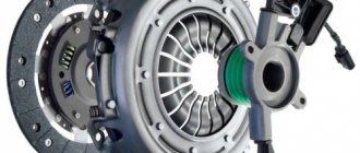
Clutch Inspection and Maintenance
First of all, it is worth considering what the clutch drive consists of. The design of this element includes the following parts:
- pedal;
- spring;
- main and working cylinders.
The latter is equipped with a pneumatic amplifier. Additionally, the design provides various pipes and hoses. They are used to transport working fluid. The fluid comes from the main cylinder. Through a special hose it is transferred to a pneumatic amplifier and a compensation tank.
Any actions to configure or pump the MAZ PSU require a complete inspection of the vehicle’s drive system. To do this you will need:
- Check the element for tightness. This is done by pressing the pedal about two or three times. Air leaks can be detected by ear. If the leak is weak and no extraneous sounds are heard, then it is checked visually using a soap or other solution. If a breakdown is detected, the failed elements are tightened or completely replaced.
- Check the condition of the fluid and its level inside the compensator tank. The optimal volume of liquid should be 15-20 mm below the edge of the container neck. If the level is reduced, then it is necessary to top it up to the required volume. It is important to use liquids of the same brand, otherwise problems may arise during operation.
- Check the functionality of the release springs, which are attached to the clutch pedal and the fork shaft lever. If a malfunction is detected, it must be eliminated by replacing the elements.
Additionally, during the inspection, you should check how tight the fastening bolts are, which are responsible for fixing the pneumatic amplifier, and also drain the damaged condensate that is inside the amplifier.
How to pump up a PSU - quickly and efficiently
When replacing the PSU or clutch master cylinder, you have to refill the system with brake fluid. How to pump a PSU quickly and efficiently. To remove air pockets from tubes and cylinders. The usual method of pumping by pressing the pedal and releasing air through the bypass valve, as a rule, does not give any results. Therefore, we have to use alternative pumping options.
The fastest way to upgrade
The simplest and most effective way is to fill the brake fluid through the PSU bypass valve. To do this, you need to use a regular pump for inflating car tires. Pour liquid into it. Connect the hose to the PSU bypass valve and fill the fluid until it appears in the expansion tank of the clutch master cylinder. After this, close the bypass valve and press the clutch pedal several times. All clutches are bled. And you don't need to put in any more effort.
Cunning trick
If you have already filled the liquid through the expansion tank. But you can’t pump the clutch; you can cheat the situation in another way. I can’t say one hundred percent why this happens. But if you press the pedal a little and fix the piston of the clutch master cylinder with a stiff wire. So that the piston cannot return to its original position.
pumping method
When you press the pedal again, the clutch begins to pump. If you do this operation several times, the clutch will swing completely. This method almost always helps. Apparently, air is being squeezed out of the cylinder cavity. And it starts working, which leads to the desired result.
Extreme case
How to pump up a PSU on a KamAZ when nothing else helps. Forcefully depress the clutch fork drive lever. That. Using a crowbar or a powerful pry bar, press out the clutch basket. In this case, the PSU rod that presses on the lever will be released. In this case, just a few presses on the clutch pedal will allow the rod to rest against the lever again, after which the clutch will begin to pump.
Errors when installing parts
I would also like to draw your attention to one detail. There is a rubber seal on the rod of the main working cylinder. It very often breaks and jumps off the stem. But without it, it is almost impossible to bleed the clutch, and therefore you have to constantly check its presence.
It is also worth paying attention to how the PSU is installed. If the installation on KamAZ 5320 does not raise any doubts, then on the 65115 PGU it can be installed and vice versa. And if in doubt, make sure the bypass valve is on top. Otherwise, the clutch will not bleed.
Adjustments
If no serious damage has been found and replacement of structural elements or bleeding of the clutch is not required, you can make adjustments to a number of parts. This will not only extend the life of the clutch assembly, but also improve the operation of the vehicle.
Free play adjustment
The free play of the clutch pedal should not exceed 6-15 mm. You can measure the value using a standard ruler. To do this, you will need to rest it on the floor of the cabin.
If the above values are found to be exceeded, it is recommended to adjust the gap formed between the assembly pusher and the piston. To perform the procedure correctly, you must pull the pedal up all the way, and then:
- Unscrew the nut and loosen it using a wrench.
- Rotate the finger that is responsible for connecting the lever with the eye, which is located at the top.
- Move the pedal from the top position until it touches the piston by an amount of 6-15 mm.
Next, all that remains is to tighten the crown and check the reliability of the fixation.
Adjusting clutch free play
The bearing coupling is one of the important elements in the assembly. The free play should not be more than 4 mm in order to ensure comfortable and quick engagement of the clutch. You can check whether this requirement is met by moving the lever.
To adjust, it is enough to fix the spherical nut of the pneumatic booster pusher and connect the spring to the lever structure.
Clutch pushrod adjustment
The full stroke must be more than 25 mm. Only thanks to this parameter is it possible to ensure complete disengagement of the clutch structure. If the size is smaller, this will not be possible, which will lead to rapid failure of the unit.
You can check the full stroke by pressing the clutch pedal all the way. If everything is in order, then no problems in the form of extraneous sounds or difficulties in performing the action will arise. If the value is not enough, it is recommended to check the liquid level inside the tank and also adjust the free play of the pedal.
Bleeding the MAZ clutch is undoubtedly a difficult procedure, but it can be done independently with an assistant or support. At the same time, it is not at all necessary to contact specialized centers if the car owner knows its structure and is able to solve the problem following the instructions.
How to adjust
By adjustment we mean changing the free play of the clutch release clutch. The clearance is checked by moving the fork lever away from the spherical surface of the booster pusher nut. The operation is carried out manually; to reduce the force, it is necessary to remove the lever spring. A stroke of 5-6 mm (measured at a radius of 90 mm) is normal. If the measured value is within 3 mm, then it should be brought to normal by rotating the spherical nut.
After adjustment, you need to check the full stroke of the pusher, which should be at least 25 mm. The test is performed by fully pressing the clutch pedal.
At lower values, the amplifier does not ensure full disengagement of the clutch discs.
Additionally, the free play of the pedal is adjusted, corresponding to the start of operation of the master cylinder. The value depends on the gap between the piston and the pusher. A normal travel range is 6-12mm, measured across the middle of the pedal. The gap between the piston and the pusher is adjusted by turning the eccentric pin. The adjustment is performed with the clutch pedal fully released (until it contacts the rubber stop). The finger rotates until the required free play is obtained. Then the nut on the regulator is tightened and the safety pin is installed.
Read also: Champion oil for 4-stroke engines