The structure of the Ural braking system
The unit in question is focused on ensuring a smooth stop of the truck with deceleration or completely. Efficiency does not depend on the speed of movement before braking, terrain features, road surface and other subjective and objective factors.
The Ural brakes are equipped with a mixed pneumohydraulic drive with a pair of circuits. The design is responsible for slowing down all six wheels along with the trailer. In this case, the front and rear elements brake separately along the axles. The process itself is activated by pressing the pedal from the driver's cabin. The movable lever is aggregated with a two-section stop valve through connecting rods and fixing parts.
The Ural service braking system consists of the following elements:
- a wheel cylinder, two parts of which are located in one housing;
- brake shield;
- adjusting eccentric, adjustable using a rotary screw and a key;
- pads located on the axes of the supports;
- friction type linings;
- connecting parts in the form of valves, hoses, holders.
The design of the brake mechanism of the Ural 4320 and 5557 car
The working brake system of the Urals of the designated brands is designed to ensure gradual braking of the vehicle partially or to a complete stop, without depending on its speed before braking, terrain features (descent or ascent), specifics of the road surface and other factors.
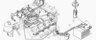
The brake system of the Ural vehicle, assembly models 4320 and 5557, has a mixed type drive (pneumohydraulics), consisting of two circuits. At the same time, it is responsible for braking all six wheels, including the trailer, with the front and rear braking separately (on the axles).
The braking process is started by the brake pedal from the driver's cabin, which is connected by rods and levers to a brake valve, consisting of two sections.
Service brake device:
- A wheel cylinder consisting of two parts located in one housing.
- Brake shield.
- An eccentric for adjustment, which is carried out by turning the bolt using a key.
- Brake pads installed on supporting axles.
- Friction lining.
- Connecting elements - hoses, washers, holders, valves and others.
Service brake device Ural 4320
Brake adjustment process
The service brake adjustment algorithm includes the following sequence of actions:
Adjusting the service brake Ural 4320
- Using a wrench, turn the eccentrics of both brake pads until they stop.
- The left eccentric must be rotated against the clock hand, and the right one - along the clock.
- Loosen the eccentrics by turning them in the opposite direction by half the head of the axle bolt, which is comparable to turning the key 30 degrees.
- Carry out the above steps for all wheels.
- Check the correctness of the adjustment by assessing whether the brake drums heat up while the Urals are moving.
When adjusting the brakes, it is important to be careful not to change the factory location of their support axles in the brake pads. It is necessary to adjust the gaps only in parallel with changing the friction linings or the pads themselves. This is done by turning the support axes and inserting a special probe, the length of which is 200 mm, and the thickness depends on the position of the edge of the overlay and can have values of 0.2 and 0.35 mm. Oily linings must be thoroughly washed with gasoline.
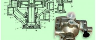
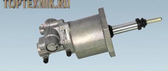
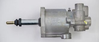
Master brake cylinder
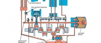
This part is responsible for controlling the truck's working system. Increased reliability is ensured by two elements equipped with pneumatic amplifiers. The principle of operation of the Ural brake system is that the valve in the shut-off valve opens after pressing the pedal in the driver’s cabin. Air masses enter through special channels and holes into the piston of the reinforcing pneumatic unit.
Air is supplied to the second piston through radial sockets in the rod. Under pressure, all incoming masses act on the main cylinder, displacing fluid into the TM (brake line). When the car's brakes are released, air is released into the atmosphere through the stop valve. In this case, the pistons of the main center and the pneumatic amplifier return to their initial position. The front counterparts have indicators that notify you of possible problems with the car’s brakes.
Adjusting the pneumatic-hydraulic drive
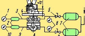
Drive diagram of the Ural service brakes
The Ural pneumohydraulic drive does not require adjustment and does not require maintenance.
The tightness of a separate pneumatic system is checked by a sharp decrease in pressure on a pressure gauge with two arrows (not lower than 700 kPa), which is located among the driver’s control instruments in the cabin. After stopping the engine (the brake pedal is not pressed), the pressure gauge needles should not twitch much or move noticeably. The same should be observed when the brake pedal is pressed for 20 seconds. At the same time, the tightness of the hydraulic part is assessed.
The functionality of the entire drive is checked by assessing the pressure (650–800 kPa) in all three circuits on pressure gauges connected to the control valves.
Peculiarities
The Ural brake system is equipped with drum mechanisms that are completely interchangeable. The pneumatic structure itself forms separate brake compartments for different parts of the machine (trailer, front, rear axle). If there is a malfunction in one segment, the remaining analogues in operation are responsible for braking.
Below is a diagram of the master cylinder with explanations.
- Front pneumatic cylinder.
- Spacer element.
- Radial socket.
- Rear pneumatic cylinder.
- Stock.
- Compression screw.
- Nuts.
- Indicator.
- Main cylinder.
- Cork.
- Brake fluid reservoir.
Dismantling and disassembly algorithm
- First of all, you must turn the nuts to remove the driveshaft of the middle axle drive.
- Then you need to turn the nut and remove the bolt that secures the ejection pipe to the third frame cross member.
- Turn the screw fastening elements of the drum to the flange, lift the ejection pipe upward and remove the drum.
- Remove the springs, ties and pads.
- Unpin and remove the pin, and also unhook the rod from the lever.
- Undo the cotter pin and unscrew the nut that secures the flange, then press the flange off the rear axle drive shaft of the transfer case.
- Turn the bolts and remove the oil trap, gasket and brake shield.
- Turn the bolt and remove the adjustment lever.
- Dismantle the retaining ring and remove the release knuckle.
- If necessary, remove the fist expansion bushing from the shield bracket structure.
Parking mechanism
The Ural manual brake system is designed to stop the vehicle when parked on slopes and inclines. While driving, the mechanism is used only in emergency cases. The working drive of the unit is mechanical, the lever is located on the side of the driver’s seat on the right. This element aggregates with a trailed analogue; when it is raised to the upper position, it also activates the trailer stopper device.
Action of the parking braking mechanism of the Ural:
- raising the lever causes force to be applied to the main structure, bypassing the intermediate point;
- from the lever element the impulse passes through the rod to the block (to the left or right, depending on the rotation of the drum);
- the block is unhooked from the connection pin and rotates in the direction of travel, pressing the second block part.
Ural hand brake
The parking brake mechanism of the Urals (handbrake) is designed for braking the Urals during parking and on slopes (during movement it is used only in emergency cases). The handbrake drive is mechanical, and the lever is located on the side of the driver's seat under the right hand.
The handbrake lever is also connected to the trailer braking lever - when it is raised to the top position, the trailer brakes are also activated.
Parking brake mechanism of the Urals
The operating principle of the Ural manual brake mechanism is as follows:
- When the lever is raised, the force from it, bypassing the intermediate one, is transferred to the release lever.
- From the lever through the rod, the impulse passes to one of the blocks - if the drum rotates counterclockwise, then to the left, while along the way, to the right.
- The block is disconnected from the support pin, pressed against the drum, rotated in the direction of rotation and presses the second block.
Adjusting the brake pad clearance of the Ural-4320 car
Auxiliary brake
The additional braking system of the Ural is aimed at holding the vehicle on long descents. The controller key is located on the floor of the control cabin. Pressing it organizes the following processes:
- compressed air is supplied to pneumatic cylinders;
- the flow affects the pistons with their subsequent movement;
- these elements overlap the dampers, which creates opposite pressure, providing braking force;
- synchronously the impulse is transformed to the trailer braking structure.
URAL 5557 30 (31) — Parking brake
Adjusting lever assembly
| 1 | call to order | ||
| 5 | 250515-P29 | 1 | call to order |
| 6 | 252137-P2 | 1 | call to order |
| 8 | 252006-P29 | 1 | call to order |
| 10 | 4320-3507162 | 1 | call to order |
| 11 | 5323-3507047 | 2 | call to order |
| 14 | 250512-P29 | 2 | call to order |
| 15 | 252020-P29 | 1 | call to order |
| 16 | 14-0283 | 2 | call to order |
| 18 | 4320-3507166 | 1 | call to order |
| 19 | 4320-3507156-10 | 1 | call to order |
| 20 | 4320-3507164-10 | 1 | call to order |
| 21 | 4320-3507163-10 | 1 | call to order |
| 22 | 260087-P52 | 1 | call to order |
| 23 | 258039-P29 | 2 | call to order |
| 24 | 4320-3507015-01 | 1 | call to order |
| 25 | 375-3507020-02 | 1 | call to order |
| 28 | 260054-P52 | 1 | call to order |
| 32 | 4320-3507160 | 1 | call to order |
| 33 | 375-3507126-10 | 1 | call |
| 34 | 4320-3507005-01 Brake shield with axle assembly | 1 | call to order |
| 35 | 4320-3507174 | 1 | call to order |
| 37 | 252135-P2 |
Brake valve drive
The brake valve drive device with a description of the elements is given below.
- Working pedal.
- Lever arm.
- Adjustment screw.
- Traction fork.
- Fixing nut.
- Drive traction.
- Brake valve lever.
- Bracket.
The safety valve must be adjusted if it does not maintain the pressure in the Ural brake system at the specified positions. Adjustment is carried out by rotating the corresponding screw. In this case, the pressure indicator increases, and after reaching the required parameter, the adjustment bolt is fixed with a nut. To avoid air leakage, the valve is removed, washed and cleaned (in kerosene). Workplaces are washed with soapy water and checked for wear and deformation.
Not available:
| № | Part code | Name | Part Information |
| 11-3514130-10 | Lower cylinder cover assembly | Quantity per 4320 4420 1 159383 Model 11 Group Brakes Subgroup Air brake control valve (brake valve) Serial part number 130 Additionally Not interchangeable with a part previously released under the same number | Not available |
| 11-3514132-10 | Upper cylinder cover assembly | Quantity per 4320 4420 1 159382 Model 11 Group Brakes Subgroup Air brake control valve (brake valve) Serial part number 132 Additionally Not interchangeable with a part previously released under the same number | Not available |
| 200-3514112 | Adjusting nut | Quantity per 4320 4420 1 159380 Model 200 Group Brakes Subgroup Air brake control valve (brake valve) Part serial number 112 | Not available |
| 200-3514133 | Pin | Quantity per 4320 4420 2 159387 Model 200 Group Brakes Subgroup Air brake control valve (brake valve) Part serial number 133 | Not available |
| 200-3514167-A | Adjustment sleeve | Quantity per 4320 4420 1 159378 Model 200 Group Brakes Subgroup Air brake control valve (brake valve) Serial part number 167 Additionally Interchangeable with a part previously released under the same number | Not available |
| 200-3514187-A4 | Middle bushing | 159379 Note to ensure clearance Model 200 Group Brakes Subgroup Air brake control valve (brake valve) Part serial number 187 Additionally Interchangeable with a part previously released under the same number | Not available |
| 200-3514187-A5 | Long sleeve | 159377 Note to ensure clearance Model 200 Group Brakes Subgroup Air brake control valve (brake valve) Part serial number 187 Additionally Interchangeable with a part previously released under the same number | Not available |
| 200-3514230-B | Large filter assembly | Quantity per 4320 4420 1 159385 Model 200 Group Brakes Subgroup Air brake control valve (brake valve) Serial part number 230 Additionally Interchangeable with a part previously released under the same number | Not available |
| 200-3514240 | Filter ring | Quantity per 4320 4420 1 159381 Model 200 Group Brakes Subgroup Air brake control valve (brake valve) Part number 240 | Not available |
| N-196 | Drain plug K1/2″ | Quantity per 4320 4420 1 159384 | Not available |
| 210-3514020-B | Brake valve body | Quantity per 4320 4420 1 159388 Model 210 Group Brakes Subgroup Air brake control valve (brake valve) Serial part number 020 Additionally Interchangeable with a part previously released under the same number | Not available |
| 339232 | Square K1/2-M16X1.5 | Quantity per 4320 4420 1 159389 Coating without coating | Not available |
| 200-3514041-E | Spring | Quantity per 4320 4420 2 159390 Model 200 Group Brakes Subgroup Air brake control valve (brake valve) Serial part number 041 Additionally Interchangeable with a part previously released under the same number | Not available |
| 200-3514042-B | Spring housing | Quantity per 4320 4420 2 159391 Model 200 Group Brakes Subgroup Air brake control valve (brake valve) Serial part number 042 Additionally Interchangeable with a part previously released under the same number | Not available |
| 200-3514045-B | Ring | Quantity per 4320 4420 2 159392 Model 200 Group Brakes Subgroup Air brake control valve (brake valve) Serial part number 045 Additionally Interchangeable with a part previously released under the same number | Not available |
| 200-3514033 | Valve washer | Quantity per 4320 4420 2 159393 Model 200 Group Brakes Subgroup Air brake control valve (brake valve) Part number 033 | Not available |
| 200-3514032-A1 | Brake valve | Quantity per 4320 4420 2 159394 Model 200 Group Brakes Subgroup Air brake control valve (brake valve) Serial part number 032 Additionally Interchangeable with a part previously released under the same number | Not available |
| 339054 | Square K 1/2-M20X1.5 | Quantity per 4320 4420 3 159395 Coating without coating | Not available |
| 339055 | Square K 1/2-M20X1.5 | Quantity per 4320 4420 1 159396 Coating without coating | Not available |
| 11-3514238 | Pad | Quantity per 4320 4420 1 159397 Model 11 Group Brakes Subgroup Air brake control valve (brake valve) Part serial number 238 | Not available |
| 200-3514095 | Return spring | Quantity per 4320 4420 2 159398 Model 200 Group Brakes Subgroup Air brake control valve (brake valve) Part number 095 | Not available |
| 252136-P9 | Spring washer 10 | Quantity per 4320 4420 3 159400 Blued coating | Not available |
| 331480-P29S | Bolt M10x202 | Quantity per 4320 4420 3 159401 Coating without coating | Not available |
| 375-3514150-B | Brake valve bracket | Quantity per 4320 4420 1 159402 Model 375 Group Brakes Subgroup Air brake control valve (brake valve) Part serial number 150 Additionally Interchangeable with a part previously released under the same number | Not available |
| 252156-P9 | Spring washer 10 | Quantity per 4320 4420 4 159403 Blued coating | Not available |
| 11-3514131-10 | Lower cylinder cover with pins assembly | Quantity per 4320 4420 1 159405 Model 11 Group Brakes Subgroup Air brake control valve (brake valve) Serial part number 131 Additionally Not interchangeable with a part previously released under the same number | Not available |
| 200-3514170-A | Trailer braking advance adjustment ring | Quantity per 4320 4420 1 159406 Model 200 Group Brakes Subgroup Air brake control valve (brake valve) Serial part number 170 Additionally Interchangeable with a part previously released under the same number | Not available |
| 200-3514165 | Traction spring | Quantity per 4320 4420 1 159407 Model 200 Group Brakes Subgroup Air brake control valve (brake valve) Part number 165 | Not available |
| 200-3514162 | Adjusting nut | Quantity per 4320 4420 1 159408 Model 200 Group Brakes Subgroup Air brake control valve (brake valve) Part number 162 | Not available |
| 11-3514138 | Dust protector cover | Quantity per 4320 4420 1 159409 Model 11 Group Brakes Subgroup Air brake control valve (brake valve) Part serial number 138 | Not available |
| 258052-P29 | Cotter pin 4x20 | Quantity per 4320 4420 1 159410 Galvanizing and passivation coating (zinc with chromating) | Not available |
| 260088-P29 | Finger 12x38 | Quantity per 4320 4420 1 159411 Galvanizing and passivation coating (zinc with chromating) | Not available |
| 200-3514206 | Axle bushing | Quantity per 4320 4420 2 159412 Model 200 Group Brakes Subgroup Air brake control valve (brake valve) Part number 206 | Not available |
| 11-3514160-01 | Lower cylinder thrust | Quantity per 4320 4420 1 159413 Model 11 Group Brakes Subgroup Air brake control valve (brake valve) Part number 160 | Not available |
| 11-3514230 | Ring sealing | Quantity per 4320 4420 1 159414 Model 11 Group Brakes Subgroup Air brake control valve (brake valve) Part number 230 | Not available |
| 11-3514232 | Ring sealing | Quantity per 4320 4420 1 159415 Model 11 Group Brakes Subgroup Air brake control valve (brake valve) Part serial number 232 | Not available |
| 200-3514172-B | Adjuster Ring Bolt | Quantity per 4320 4420 1 159417 Model 200 Group Brakes Subgroup Air brake control valve (brake valve) Serial part number 172 Additionally Interchangeable with a part previously released under the same number | Not available |
| 200-3514163 | Thrust washer | Quantity per 4320 4420 1 159418 Model 200 Group Brakes Subgroup Air brake control valve (brake valve) Part serial number 163 | Not available |
| 200-3514164 | Thrust washer pin | Quantity per 4320 4420 1 159419 Model 200 Group Brakes Subgroup Air brake control valve (brake valve) Part number 164 | Not available |
| 200-3514080-B2 | Lower cylinder piston | Quantity per 4320 4420 1 159420 Model 200 Group Brakes Subgroup Air brake control valve (brake valve) Serial part number 080 Additionally Interchangeable with a part previously released under the same number | Not available |
| 200-3514085-B | Piston collar | Quantity per 4320 4420 1 159421 Model 200 Group Brakes Subgroup Air brake control valve (brake valve) Serial part number 085 Additionally Interchangeable with a part previously released under the same number | Not available |
| 200-3514086-B | Piston collar | Quantity per 4320 4420 1 159422 Model 200 Group Brakes Subgroup Air brake control valve (brake valve) Serial part number 086 Additionally Interchangeable with a part previously released under the same number | Not available |
| 200-3514081-B2 | Upper cylinder piston | Quantity per 4320 4420 1 159423 Model 200 Group Brakes Subgroup Air brake control valve (brake valve) Serial part number 081 Additionally Interchangeable with a part previously released under the same number | Not available |
| 11-3514234 | Ring sealing | Quantity per 4320 4420 1 159424 Model 11 Group Brakes Subgroup Air brake control valve (brake valve) Part serial number 234 | Not available |
| 11-3514136 | Stub | Quantity per 4320 4420 1 159425 Model 11 Group Brakes Subgroup Air brake control valve (brake valve) Part serial number 136 | Not available |
| 11-3514107 | Nut and pin assembly | Quantity per 4320 4420 1 159426 Model 11 Group Brakes Subgroup Air brake control valve (brake valve) Part serial number 107 | Not available |
| 200-3514104-B | Balancing spring | Quantity per 4320 4420 1 159427 Model 200 Group Brakes Subgroup Air brake control valve (brake valve) Serial part number 104 Additionally Interchangeable with a part previously released under the same number | Not available |
| 11-3514135-10 | Upper cylinder cover | Quantity per 4320 4420 1 159428 Model 11 Group Brakes Subgroup Air brake control valve (brake valve) Serial part number 135 Additionally Not interchangeable with a part previously released under the same number | Not available |
| 200-3514119 | Locking bolt | Quantity per 4320 4420 1 159429 Model 200 Group Brakes Subgroup Air brake control valve (brake valve) Part number 119 | Not available |
| 200-3514180 | Upper cylinder thrust | 159430 Model 200 Group Brakes Subgroup Air brake control valve (brake valve) Part number 180 | Not available |
| 200-3514185 | Traction spring | Quantity per 4320 4420 1 159431 Model 200 Group Brakes Subgroup Air brake control valve (brake valve) Part number 185 | Not available |
| 11-3514114 | Balance spring tube assembly | Quantity per 4320 4420 1 159432 Model 11 Group Brakes Subgroup Air brake control valve (brake valve) Part serial number 114 | Not available |
| 200-3514139-A | Dust fuse | Quantity per 4320 4420 1 159433 Model 200 Group Brakes Subgroup Air brake control valve (brake valve) Serial part number 139 Additionally Interchangeable with a part previously released under the same number | Not available |
| 200-3514187-A3 | Long sleeve (for spare parts only) | 159434 Note for securing clearance Model 200 Group Brakes Subgroup Air brake control valve (brake valve) Part serial number 187 Additionally Interchangeable with a part previously released under the same number | Not available |
| 200-3514144V | Brake valve lever | Quantity per 4320 4420 1 159435 Model 200 Group Brakes Subgroup Air brake control valve (brake valve) Serial part number 144 Additionally Interchangeable with a part previously released under the same number | Not available |
| 312314-P29 | Washer 16 | Quantity per 4320 4420 1 159436 Galvanizing and passivation coating (zinc with chromating) | Not available |
| 258055-P29 | Cotter pin 4x35 | Quantity per 4320 4420 1 159437 Galvanizing and passivation coating (zinc with chromating) | Not available |
| 250871-P29 | Nut M16x1.5 | Quantity per 4320 4420 1 159438 Galvanizing and passivation coating (zinc with chromating) | Not available |
| 200-3514200-B | Trailer brake manual lever | Quantity per 4320 4420 1 159439 Model 200 Group Brakes Subgroup Air brake control valve (brake valve) Serial part number 200 Additionally Interchangeable with a part previously released under the same number | Not available |
| 258062-P29 | Cotter pin 4Х20.016 | Quantity per 4320 4420 1 159442 Galvanizing and passivation coating (zinc with chromating) | Not available |
| 200-3514205-B | Lever axis | Quantity per 4320 4420 1 159443 Model 200 Group Brakes Subgroup Air brake control valve (brake valve) Serial part number 205 Additionally Interchangeable with a part previously released under the same number | Not available |
| 200-3514212-B | Return axle spring | Quantity per 4320 4420 1 159444 Model 200 Group Brakes Subgroup Air brake control valve (brake valve) Serial part number 212 Additionally Interchangeable with a part previously released under the same number | Not available |
Adjustment and bleeding
Bleeding the Ural brake system with simultaneous adjustments is carried out as follows:
- Using a special wrench, turn the eccentrics of both brake pads until they stop.
- The left analog is rotated counterclockwise, the right element is rotated in the direction of travel.
- Then the eccentrics are loosened by turning the axial screw head 50% in the opposite direction.
- These steps must be repeated for all wheels.
- Check the correctness of the adjustment by assessing the heating of the drums while the vehicle is moving. When carrying out this procedure, the relationship between the factory location of the brake pads and the support axles should be observed. The gaps are adjusted by rotating the axes with the introduction of a special shunt device, which is 20 cm in length and thickness varies from 0.2 to 0.35 mm. Linings that are excessively oily are treated with gasoline.
The design of the brake mechanism of the Ural 4320 and 5557 car
The working brake system of the Urals of the designated brands is designed to ensure gradual braking of the vehicle partially or to a complete stop, without depending on its speed before braking, terrain features (descent or ascent), specifics of the road surface and other factors.
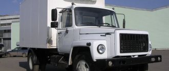
Brake system Ural
The brake system of the Ural vehicle, assembly models 4320 and 5557, has a mixed type drive (pneumohydraulics), consisting of two circuits. At the same time, it is responsible for braking all six wheels, including the trailer, with the front and rear braking separately (on the axles).
The braking process is started by the brake pedal from the driver's cabin, which is connected by rods and levers to a brake valve, consisting of two sections.
Service brake device:
- A wheel cylinder consisting of two parts located in one housing.
- Brake shield.
- An eccentric for adjustment, which is carried out by turning the bolt using a key.
- Brake pads installed on supporting axles.
- Friction lining.
- Connecting elements - hoses, washers, holders, valves and others.
Service brake device Ural 4320
Brake adjustment process
The service brake adjustment algorithm includes the following sequence of actions:
Adjusting the service brake Ural 4320
- Using a wrench, turn the eccentrics of both brake pads until they stop.
- The left eccentric must be rotated against the clock hand, and the right one - along the clock.
- Loosen the eccentrics by turning them in the opposite direction by half the head of the axle bolt, which is comparable to turning the key 30 degrees.
- Carry out the above steps for all wheels.
- Check the correctness of the adjustment by assessing whether the brake drums heat up while the Urals are moving.
When adjusting the brakes, it is important to be careful not to change the factory location of their support axles in the brake pads. It is necessary to adjust the gaps only in parallel with changing the friction linings or the pads themselves. This is done by turning the support axes and inserting a special probe, the length of which is 200 mm, and the thickness depends on the position of the edge of the overlay and can have values of 0.2 and 0.35 mm. Oily linings must be thoroughly washed with gasoline.
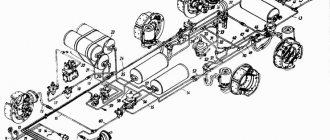
Pneumohydraulic drive
The Ural air braking system is a mixed unit that includes not only pneumatics, but also hydraulic mechanisms. The block consists of a pair of working circuits (for front and rear wheels).
The main two brake circuits of the said truck include:
- atmospheric cylinders of various configurations, which are placed parallel to each other;
- a brake valve, the upper part of which belongs to the first compartment, and the second compartment to the second;
- pneumatic brake booster with cylinder wheel;
- work force regulator.
Dismantling and disassembling parking brake drive parts
- Unscrew and remove the pin that secures the connection between the rod and the lever.
- Remove the four cab bolts and then remove the bracket structure.
- Unscrew the lever axle and remove the washer and lever structure.
- Remove the four bolts and dismantle the bracket structure assembled with the lever structure.
- Disassemble the bracket (you will need to turn the mounting lever bolts on the ox and dismantle the lever structure assembled with the pawl, lever and pawl rod).
- Remove the lever key from the shaft.
- Turn the bolts that secure the flange and the bolt that secures the linkage to the ox, and remove the flange.
- Press out the shaft assembly with the key from the lever structure and from the bracket structure through the passage under the flange.
- Remove the lever key from the shaft; if necessary, also turn the two bolts and remove the sector.
- Press the bushing out of the flange and bracket structure.
- Turn the bolt and remove the lever structure and its key from the shaft.
- Remove the shaft assembly from the bracket structure with the lever structure pressed onto the splined shaft tip.
- There is no need to disconnect the splined tip of the shaft from the lever; if necessary, press the bushing out of the bracket structure.
- If the linings are worn out - if less than half a centimeter remains from the surface of the rivet heads - replace them with new ones.
- If the working surface of the brake drum and shoe assembly with linings is heavily worn (pay attention to the ring grooves), grind them to standard dimensions.
- When turning the block using special equipment, do not forget about the base. An important point: between the release fist and the block crackers you need to place plates, the thickness of which should be one millimeter.
- Oil-coated shoe linings must be treated using unleaded gasoline and then dried. It is advisable to replace those linings that have “looseness” on the surface and traces of delamination due to thermal effects.
- Cracks and other defects of the pads are unacceptable. If the fasteners are loose, be sure to tighten the screws.
Recommendations
The third circuit has a separate air tank and special valves to control the operation of the trailer wheels. It also includes connection heads that differ in configuration, depending on the drive they are intended for. The third circuit is responsible for stopping the trailer.
The compressor operates in cooperation with the regulator, which sends air flow to safety valves, which distribute the resulting mixture between all tanks in each circuit compartment. All chambers are equipped with pressure gauges that allow you to control the pressure indicator.
Malfunctions of the Ural brake system
Among the malfunctions of this design, there are several malfunctions that occur most often in practice:
- weak pressure build-up in receivers due to breakage of main bodies or connections;
- filling the balloon circuits in insufficient volume, which provokes failure of the correction valves or excessive contamination of the associated components;
- low pressure in the air tanks on the trailer, which is most often caused by cracks in the parts;
- excessive pressure in the receivers due to a malfunction of the controller or pressure gauge;
- malfunction of the compression mechanism, which indicates serious wear of the compressor piston unit.
If critical malfunctions occur in this system, operating the vehicle is strictly prohibited. You should correct the problem on site or take the car to a repair bay using a rigid hitch type.
Repair work
When repairing parts of the Ural brake system, all devices and elements should be carefully removed, washed thoroughly and carefully checked for defects. The assembly is disassembled as follows:
- Using a jack, lift the serviced axle, remove the wheel and hub cover, then unscrew the tire inflation angle by dismantling the axle shaft using a puller.
- Bend down the lock washer and the outer lock, remove the lock and inner washer.
- The brake hub and drum are dismantled along with bearings, locking brackets, and pad springs. The bushing and pad pin are thoroughly cleaned.
- Unscrew the pipeline with bolts, remove the wheel-type cylinder, and remove the block support protrusions.
- Dismantle the brake shield and felt seal.
- When disassembling the main shopping center, do not unscrew the plug.
- It is recommended to disassemble the compressor main unit only if absolutely necessary. It is pressed out using a special puller.
- All oily and contaminated parts of the brake system of the Ural vehicle are washed in gasoline. If the distance from the surface of the linings to the rivet heads is less than 0.5 mm, the parts must be replaced with new modifications.
- The shoe elements of the hand brake are processed together with the expansion cam.
- Drums with ring grooves more than 2 millimeters deep must be machined.
- It would be a good idea to hone wheel cylinders that show signs of corrosion and abrasions. Items showing signs of excessive wear should be replaced.
Adjusting the handbrake: adjust the handbrake correctly. How to tighten the handbrake on a Ural 4320
The parking brake drive is connected to the brake valve lever due to special levers and rods, which makes it possible, along with stopping the vehicle using the parking brake, to turn on the service brakes of the trailer or semi-trailer.
Among the root causes of design defects are the following:
- Unfavorable effects of oil (“oiling”).
- Deformation due to temperature effects
- Wear of brake pad linings.
- Loosening the bolts that secure the brake shield to the transfer case.
- Wear of the sector or pawl of the lever (these defects interfere with the possibility of normal fixation of the lever).