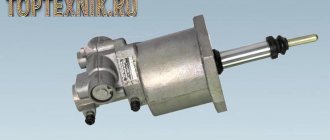
The PGU unit on the MAZ is designed to reduce the force required to disengage the clutch. The machines contain units of our own design, as well as imported Wabco products. For example, PGU Vabko 9700514370 (for MAZ 5516, 5336, 437041 (Zubrenok), 5551) or PGU Volchansky AZ 11.1602410-40 (suitable for MAZ-5440). The operating principle of the devices is the same.
Clutch Inspection and Maintenance
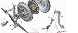
First of all, it is worth considering what the clutch drive consists of. The design of this element includes the following parts:
- pedal;
- spring;
- main and working cylinders.
The latter is equipped with a pneumatic amplifier. Additionally, the design provides various pipes and hoses. They are used to transport working fluid. The fluid comes from the main cylinder. Through a special hose it is transferred to a pneumatic amplifier and a compensation tank.
Any actions to configure or pump the MAZ PSU require a complete inspection of the vehicle’s drive system. To do this you will need:
- Check the element for tightness. This is done by pressing the pedal about two or three times. Air leaks can be detected by ear. If the leak is weak and no extraneous sounds are heard, then it is checked visually using a soap or other solution. If a breakdown is detected, the failed elements are tightened or completely replaced.
- Check the condition of the fluid and its level inside the compensator tank. The optimal volume of liquid should be 15-20 mm below the edge of the container neck. If the level is reduced, then it is necessary to top it up to the required volume. It is important to use liquids of the same brand, otherwise problems may arise during operation.
- Check the functionality of the release springs, which are attached to the clutch pedal and the fork shaft lever. If a malfunction is detected, it must be eliminated by replacing the elements.
Additionally, during the inspection, you should check how tight the fastening bolts are, which are responsible for fixing the pneumatic amplifier, and also drain the damaged condensate that is inside the amplifier.
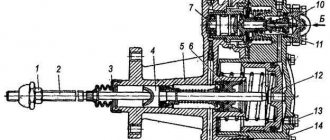
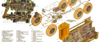
Schematic diagram of connection and placement of node elements
The operating principle of the KamAZ-5320 PGU is easier to understand by studying the diagram below with explanations.
- a – standard diagram of interaction of drive parts.
- b – location and fixation of node elements.
- 1 – clutch pedal.
- 2 – main cylinder.
- 3 – cylindrical part of the pneumatic amplifier.
- 4 – follower mechanism of the pneumatic part.
- 5 – air duct.
- 6 – main hydraulic cylinder.
- 7 – release clutch with bearing.
- 8 – lever.
- 9 – rod.
- 10 – drive hoses and pipes.
What kind of mechanism is this
PGU is a pneumatic type hydraulic amplifier. This device consists of the following structural elements:
- piston;
- piston pusher;
- two valves - inlet and bypass;
- fuel fluid intake systems;
- complex seal;
- traffic jams;
- air compression systems;
- a protective cover that prevents the risk of damage to the amplifier structure;
- spherical nut and locknut;
- spring mechanism;
- diaphragms;
- gearbox
The pneumatic hydraulic booster must be pumped from time to time. This allows the clutch system to work as it should. The level of safety increases, because when you press the appropriate pedal, there is no subsidence or slippage - very dangerous phenomena.
Pumping of the CCGT unit is relevant for any models and modifications of KamAZ, for example, 43114, 5511, 53501, 65117, 6520, 43118, 55111, etc.
How to pump up a PSU - quickly and efficiently
When replacing the PSU or clutch master cylinder, you have to refill the system with brake fluid. How to pump a PSU quickly and efficiently. To remove air pockets from tubes and cylinders. The usual method of pumping by pressing the pedal and releasing air through the bypass valve, as a rule, does not give any results. Therefore, we have to use alternative pumping options.
The fastest way to upgrade
The simplest and most effective way is to fill the brake fluid through the PSU bypass valve. To do this, you need to use a regular pump for inflating car tires. Pour liquid into it. Connect the hose to the PSU bypass valve and fill the fluid until it appears in the expansion tank of the clutch master cylinder. After this, close the bypass valve and press the clutch pedal several times. All clutches are bled. And you don't need to put in any more effort.
Cunning trick
If you have already filled the liquid through the expansion tank. But you can’t pump the clutch; you can cheat the situation in another way. I can’t say one hundred percent why this happens. But if you press the pedal a little and fix the piston of the clutch master cylinder with a stiff wire. So that the piston cannot return to its original position.
pumping method
When you press the pedal again, the clutch begins to pump. If you do this operation several times, the clutch will swing completely. This method almost always helps. Apparently, air is being squeezed out of the cylinder cavity. And it starts working, which leads to the desired result.
Extreme case
How to pump up a PSU on a KamAZ when nothing else helps. Forcefully depress the clutch fork drive lever. That. Using a crowbar or a powerful pry bar, press out the clutch basket. In this case, the PSU rod that presses on the lever will be released. In this case, just a few presses on the clutch pedal will allow the rod to rest against the lever again, after which the clutch will begin to pump.
Errors when installing parts
I would also like to draw your attention to one detail. There is a rubber seal on the rod of the main working cylinder. It very often breaks and jumps off the stem. But without it, it is almost impossible to bleed the clutch, and therefore you have to constantly check its presence.
It is also worth paying attention to how the PSU is installed. If the installation on KamAZ 5320 does not raise any doubts, then on the 65115 PGU it can be installed and vice versa. And if in doubt, make sure the bypass valve is on top. Otherwise, the clutch will not bleed.
Check after installation:
- After completing pumping of the PSU, measure the maximum stroke of the pneumohydraulic booster rod, which should be at least 14 mm (for GAZ, PAZ clutches) and 18 mm (for YaMZ clutch).
- Measure the pressure in the hydraulic cylinder of the PSU or measure the volume of fluid displaced when pressing the clutch pedal once, which should be 7-8 cm3. The liquid pressure must be at least 4 kgf/cm2 with an air pressure of at least 7 kgf/cm2 at the amplifier input.
- After pumping the PSU, the maximum misalignment of the rod extension when pressing the clutch pedal should not exceed ±1.50 from the initial state.
- For boosters with a mechanical clutch lining wear sensor, you need to make sure that the tip of the sensor does not protrude from the booster pneumatic cylinder housing. As the linings of the driven clutch disk wear, the sensor “comes out” of the pneumatic cylinder body and, according to the markings on the sensor, the degree of wear of the linings is determined.
If adjusting the MAZ PGU does not help and the amplifier is leaking, then we recommend replacing the part with a new one. We are an official dealer, we recommend buying on our website or by calling: 8, 8 (017) 300-95-00
The operating principle of the unit.
The CCGT is mounted on the cabin panel. The clutch accelerator is connected to the unit via a pusher. When the clutch is disengaged, the rod is pressed against the piston of the pneumatic cylinder. When you press the accelerator, fluid flows through the channel into the amplifier. The movement of the pusher opens the valve of the pneumatic system. When the required pressure is reached, the inlet valve opens completely and air enters the pneumatic cylinder chamber. The piston together with the clutch release pusher reaches the top point. A special feature of the piston operation is the effect of two forces on it. On the one hand, it is exerted by the pressure of the compressed air of the pneumatic system, on the other, by the action of the working fluid of the hydraulic booster. The systems are designed to provide maximum comfort for the driver to operate the clutch mechanism. When the pedal is released, the pressure of the hydraulic booster fluid decreases and the pneumatic cylinder stops its operation. The exhaust valve opens and the air escapes to the atmosphere. If the unit breaks down, the clutch is disengaged only through the operation of the hydraulic booster.
Pneumatic system design.
The mechanism consists of a tank mounted on a frame, a single safety valve and lines. The air supply to the amplifier is carried out through a separate circuit of the system. The valve is located on the reservoir and separates the air lines leading to the clutch mechanism and other components. There is a tap to drain the condensate formed in the cylinders.
PGU device.
The amplifier consists of a housing, inside of which there is a piston and a pusher. The piston has a cuff and moves in the axial direction. The amplifier housing is closed on top with a lid through which the pusher passes. To protect against dirt and dust, a wiper is installed in the mechanism on the amplifier cover. The pusher is connected to the clutch release accelerator by a fork mechanism. The accelerator is installed on the axis of the bracket. Air is supplied to the unit from cylinders through the operation of a valve mechanism.
Main malfunctions of the mechanism.
Ural 5557 PGU and hydraulic booster fail for the following reasons:
- Swelling of the sealing ring.
- Incorrect adjustment of the mechanism.
- Wear of cuffs and other elements.
- Release cylinder fork bend
- Fork axle wear.
- Pedal failure.
- Drive jammed.
- Valve wear.
If the mechanism jams, it is worth disassembling it and rinsing it in gasoline or kerosene. Wear of sealing rings and valves leads to leakage of compressed air from the cylinders. This problem can be noticed by the constant “hissing” of the unit. If the problems of the clutch PSU are not corrected in a timely manner, breakdowns of the hydraulic booster may occur in the future, which will lead to a stop in the operation of the vehicle and the need to install new spare parts from the Ural plant.
In what cases is it necessary to replace the unit?
Intensive use of the vehicle in urban conditions, where acceleration and braking often occurs, entails rapid wear of the transmission mechanisms. Frequently pressing the clutch accelerator entails wear on the amplifier itself. Ultimately, when the mechanism wears out, the smoothness of starting and shifting gears significantly deteriorates. In addition, sharp vibrations are transmitted from the engine through the transmission to the car frame. The PSU solves many problems, so its malfunction entails loss of comfort in controlling the mechanism and the vehicle as a whole.
Clutch URAL 4320
Adjusting the clutch pedal.
One of the problems with the operation of the amplifier is incorrect installation of the accelerator. To fix the problem, adjustments must be made. It is carried out in several stages:
Cylinder Ural 4320
- Bleed the air from the cylinders.
- Move the pneumatic cylinder to the upper position and fix it.
- Press the clutch accelerator to the floor.
- Adjust free play.
- Measure the stroke of the pusher with the engine running.
Production
The KamAZ-5320 PGU device is suitable for many model modifications of this manufacturer. Most old and new tractors, dump trucks, and military variants are equipped with pneumatic-hydraulic power steering. Modern modifications produced by various companies have the following designations:
- Spare parts for KamAZ (PGU) manufactured by KamAZ OJSC (catalog number 5320) with vertical placement of the tracking device. The device above the cylinder body is used on variations under the index 4310, 5320, 4318 and some others.
- WABCO. CCGT units under this brand are manufactured in the USA and are distinguished by their reliability and compact dimensions. This equipment is equipped with a system for monitoring the condition of the linings, the level of wear of which can be determined without dismantling the power unit. Most trucks with a 154 series transmission are equipped with this type of air-hydraulic equipment.
- Pneumatic hydraulic clutch booster "VABKO" for models with ZF type gearbox.
- Analogues produced at a plant in Ukraine (Volchansk) or Turkey (Yumak).
In terms of choosing an amplifier, experts recommend purchasing the same brand and model that was originally installed on the machine. This will ensure the most correct interaction between the amplifier and the clutch mechanism. Before changing the unit to a new variation, consult a specialist.
Bleeding and adjustment of PGU and GUR on KamAZ trucks
KamAZ PGU is a device designed to reduce the level of pressure exerted by the driver on the clutch pedal.
PGU - hydraulic power steering of a KamAZ pneumatic clutch type.
Design and principle of operation
The PGU device includes:
- spherical type nut;
- lock nut;
- a piston pusher that deactivates the clutch system;
- a cover that protects against damage;
- piston;
- complex type seal;
- bypass and inlet valve;
- cork;
- fuel fluid supply;
- system for compressing air flow.
The diagram also includes the following elements:
- spring mechanism;
- gearbox;
- diaphragm seats.
The operating principle of the PSU is as follows:
- The driver presses the clutch pedal.
- Under the pressure of the fuel fluid, the rod and piston part of the mechanism are activated.
- Movement occurs until the intake valve opens.
- The air flow moves in the direction of the pneumatic piston.
- The fork is retracted and the clutch system is disengaged.
Design and principle of operation
Pneumohydraulic amplifiers (PGU) are produced in several modifications, differing in the location of the lines and the design of the working rod and protective cover.
The CCGT device includes the following parts:
- a hydraulic cylinder installed under the clutch pedal, together with a piston and a return spring;
- the pneumatic part, which includes a piston common to pneumatics and hydraulics, a rod and a return spring;
- a control mechanism equipped with a diaphragm with a release valve and a return spring;
- valve mechanism (for intake and exhaust) with a common rod and an elastic element to return the parts to the neutral position;
- lining wear indicator rod.
To eliminate gaps, the design has preload springs. There is no play in the connections to the clutch control fork, which allows you to monitor the degree of wear of the friction linings. As the thickness of the material decreases, the piston is recessed into the depth of the amplifier body. The piston acts on a special indicator that informs the driver about the remaining clutch life. Replacement of the driven disk or linings is required when the indicator rod reaches a length of 23 mm.
Bleeding the clutch
Many MAZ owners are well aware of the problems that may arise during the operation of the car. Among such problems, air getting inside the hydraulic element of the clutch assembly is quite common.
Among the reasons leading to such trouble are:
- pipe damage;
- loose tightening of certain parts.
There is a sequence of actions that can be used to bleed the MAZ clutch and restore or even improve the performance of the entire unit.
Materials and tools
Before you begin, you should prepare the necessary tools and materials. The main equipment that may be required during repairs includes:
- Brake fluid. It is recommended to be as careful as possible when using this liquid, as its composition is poisonous.
- A set of tools that every driver has.
- A container in which you will need to pour out the brake fluid.
- Hose. The diameter of the hose must match the diameter of the drain hole.
You will also need to find an assistant, since it will be almost impossible to cope with the task alone. In addition, it will be much more convenient to pump the clutch with two or even three people. If you cannot find an assistant, then it is recommended to find a suitable device with which you can fix the clutch pedal. Such a device can be a rail or, for example, a stick made of wood or metal.
Step-by-step instruction
Many people wonder how to upgrade the PGU in MAZ? Removing air and pumping the hydraulic drive is carried out in several stages. Each of them represents the following actions:
- First of all, the car owner will need to remove the plug that is installed on the tank. This is done so that brake fluid can subsequently be poured inside to a level of 1.5 cm above the boundaries of the container lid.
- Next, you need to dismantle the cap located in the place where the bypass valve is located. When the action is completed, you need to connect a hose to the valve head and then insert the other end of this hose into the container where the brake fluid is filled.
- The third step is to unscrew the bypass valve either half a turn or a full turn. Further, the operating principle is simple. The car owner will then need to press the pedal as sharply as possible so that it quickly hits the limiter. This must be done in such a way that the release of air bubbles formed inside the liquid is stopped.
- During the pumping process, you should add liquid inside the tank, while making sure that the volume does not decrease and does not rise above 4 cm to the edge of the upper border of the neck of the container.
- When the pumping is completed, you should screw the bypass valve all the way, without releasing the pedal that is pressed all the way, and also remove the hose and return the cap to its place, fixing its position.
Completion of pumping implies another injection of liquid into the tank in order to achieve the optimal volume and continue operation of the vehicle.
You can evaluate the success of the completed task by how the pusher of the pneumatic amplifier works. If full travel has been achieved, the job has been done correctly. The same can be demonstrated by the liquid inside the main cylinder, which does not contain air and is in the optimal volume during the movement of the car and the operation of the clutch.
Service
In order for the clutch system (single or double disc) of a MAZ truck to work properly, it is necessary to carry out maintenance of not only the main mechanism, but also the auxiliary one - the pneumatic amplifier. Maintenance of the unit includes the following work:
- The CCGT should first be inspected to identify external damage that could cause liquid or air leakage;
- tighten all fixing bolts;
- drain the condensate from the pneumatic booster;
- It is also necessary to adjust the free play of the pusher and the release bearing clutch;
- Bleed the PSU and add brake fluid to the system tank to the required level (do not mix fluids of different brands).
Instructions: How to properly bleed the clutch yourself
Diagnostics and repair of a car clutch involves removing it entirely or partially from the car, disassembling and disconnecting various parts. This causes air to enter the hydraulic system of the control mechanism. Therefore, any master knows that after repairs it is necessary to bleed the car’s clutch, removing excess air from it. When repairing a car clutch on your own, or when symptoms of air entering the system appear, the driver must know how to bleed the clutch on his own.
When is it necessary to bleed the clutch?
As noted above, the clutch bleeding procedure is necessary when the hydraulic system is depressurized, which is most often caused by repair or diagnostic work. At the same time, air can also enter the hydraulic system over time when the machine is used if the connections of the clutch mechanism units have not been tightened properly. In addition, cracks in the pipeline or other malfunctions can cause air to enter the clutch.
There are several symptoms that indicate that the clutch needs to be pumped:
- The car jerks when driving;
- The clutch pedal “beats”;
- The required result is not achieved when squeezing the clutch, only after one and a half or double squeeze.
Driving a car with a faulty clutch is extremely dangerous, both for the driver and for the units. You can bleed the clutch without contacting a service center by following the instructions below.
What is required to bleed the clutch?
The clutch bleeding process can be done in the field or in the garage as it does not require many tools. To bleed the clutch alone you will need:
- New brake fluid;
- Empty container for draining brake fluid from the system;
- Automotive tool set (standard);
- Rubber hose that fits the diameter of the drain fitting;
- A device that allows you to fix the clutch is most often a “gas stop,” but other tools can be used.
Please note: You can do without a clutch locking device if you have a friend who can take on this task.
How to bleed the clutch
Important: Before you begin bleeding, you must adjust the clutch. Bleeding the clutch won't make much sense unless the cylinder piston pusher moves freely.
Before you begin bleeding the clutch, make sure that the brake fluid prepared for use complies with the vehicle manufacturer's recommendations. Using the wrong brake fluid can cause clutch failure due to swelling of the rubber linings.
Clutch bleeding is carried out according to the following plan:
- First, you need to clean the master cylinder reservoir as much as possible so that when adding brake fluid, no dirt, dust or other debris gets into it;
- After this, suitable brake fluid is added to the reservoir so that there is about 2 centimeters of free space from its upper edge;
- Next, from the bypass valve located in the upper part of the pneumatic hydraulic booster, it is necessary to remove the rubber cap and put a prepared rubber hose of a suitable diameter on it;
- You need to pour about 200 milliliters of new brake fluid into an empty container and lower the rubber hose into it;
- Next, the bypass valve is turned back one turn and the assistant is commanded to press the clutch pedal all the way. The squeezing must be done slowly, while ensuring that the hose is in the brake fluid. The release of excess air from the clutch system will be indicated by the appearance of bubbles on the surface of the brake fluid poured into the container. Important: When depressing the clutch, you need to monitor the amount of brake fluid in the reservoir. If its level drops below 3.5 centimeters from the top edge, you need to add more liquid.
- When the clutch pedal is pressed all the way, it is necessary for an assistant to continue to hold it there. At this point you need to tighten the bypass valve. After this you can release the pedal. Then the bypass valve opens again one turn, and the assistant presses the pedal. This procedure should be repeated 3-4 times. If air continues to leave the system for the fourth time, it is necessary to perform it until all of it leaves the clutch;
- After all the air has been released from the clutch, you need to tighten the bypass valve securely, remove the hose and put the cap on the fitting.
If required, after completing the work, you can add brake fluid to the recommended value - from 1.5 to 2 centimeters from the top edge of the reservoir.
power steering
KamAZ power steering (hydraulic power steering) is a mechanism that facilitates the effort required to turn while driving a vehicle.
Device
The KamAZ-5320 power steering device includes the following elements:
- Distributor of fuel flow to other mechanisms of the power steering system.
- A pump that is responsible for the circulation of working fluid and pressure indicators.
- A hydraulic cylinder that converts liquid pressure from the pump part to the cylindrical part.
- Hoses that connect all the elements of the pump part, the distributor and the hydraulic cylinder.
- An electronic unit that regulates the operation of the hydraulic booster.
- Steering wheel.
- Safety valve spring of the hydraulic system.
- Bipod shaft equipped with a gear-type sector.
- Piston-rack.
- Longitudinal and transverse thrust.
- Magnetic plug.
- Steering system housing.
- Spool.
- Centering type spring.
- Filling filter element.
Important Backhoe Loader Attachments
Malfunctions and repairs
Possible power steering malfunctions:
- Unstable vehicle movement. In this case, you need to adjust the free play of the wheel, replace the ball screw, wash all the parts, and tighten the front cover nut.
- The turning system works with great effort. This may be due to insufficient oil fluid level. Oil is poured into the hydraulic booster to the upper mark.
- Increased noise level during operation. In this case, it is recommended to wash all filter elements and replace damaged ones. Adjust the engagement system and replace damaged parts.
- Shocks while driving at high speeds. Such a breakdown may be due to wheel imbalance.
- Throws oil out of the RBL tank. It is recommended to replace the worn element and check the operation of the intake valve.
See » Construction and repair of a water separator for KamAZ
Repairing the KamAZ-4310 power steering and restoring the power steering involves replacing damaged parts and components. To perform adjustment work, you will need a dynamometer and a pressure gauge.
Replacing the oil seal
The procedure is carried out in case of oil leakage.
To change a part, prepare the following tools:
- set of wrenches;
- screwdriver;
- ratchet wrench;
- hammer;
- universal type puller.
Procedure for replacing the bipod seal:
- Drain the oil and remove the grille and radiator from the cooling system.
- Unscrew the front pulley mounting screw using a ratchet wrench.
- Remove the front pulley.
- Remove the worn or damaged oil seal and replace it with a new one.
- Using a hammer, seat the new part to a sufficient depth of the groove in the front cover.
- Replace the pulley.
- Tighten the removed bolts and add oil.
- After replacing the oil seal, you need to start the vehicle to make sure that the oil fluid no longer flows.
How to properly bleed and adjust
The process of adjusting the KamAZ power steering:
- Drain the oil fluid from the system.
- Remove the seal and unsplit the socket plug.
- Unscrew the socket plug from the safety valve.
- After replacing the damaged part, cover the hole in the valve body with a napkin.
- Adjust the distance between the piston part and the pusher.
- Remove all nicks and check the integrity of the rubber seal.
The pumping procedure is performed as follows:
- Unscrew the bypass valve.
- Turn the steering wheel to the left until the centering springs are compressed.
- Fill the pump with oil.
- Close the bypass valve.
- Move the steering wheel to the right.
- Use a pump to pump the KamAZ power steering until the release of air in the hydraulic booster stops.
Adjustments
If no serious damage has been found and replacement of structural elements or bleeding of the clutch is not required, you can make adjustments to a number of parts. This will not only extend the life of the clutch assembly, but also improve the operation of the vehicle.
Free play adjustment
The free play of the clutch pedal should not exceed 6-15 mm. You can measure the value using a standard ruler. To do this, you will need to rest it on the floor of the cabin.
If the above values are found to be exceeded, it is recommended to adjust the gap formed between the assembly pusher and the piston. To perform the procedure correctly, you must pull the pedal up all the way, and then:
- Unscrew the nut and loosen it using a wrench.
- Rotate the finger that is responsible for connecting the lever with the eye, which is located at the top.
- Move the pedal from the top position until it touches the piston by an amount of 6-15 mm.
Next, all that remains is to tighten the crown and check the reliability of the fixation.
Adjusting clutch free play
The bearing coupling is one of the important elements in the assembly. The free play should not be more than 4 mm in order to ensure comfortable and quick engagement of the clutch. You can check whether this requirement is met by moving the lever.
To adjust, it is enough to fix the spherical nut of the pneumatic booster pusher and connect the spring to the lever structure.
Clutch pushrod adjustment
The full stroke must be more than 25 mm. Only thanks to this parameter is it possible to ensure complete disengagement of the clutch structure. If the size is smaller, this will not be possible, which will lead to rapid failure of the unit.
You can check the full stroke by pressing the clutch pedal all the way. If everything is in order, then no problems in the form of extraneous sounds or difficulties in performing the action will arise. If the value is not enough, it is recommended to check the liquid level inside the tank and also adjust the free play of the pedal.
Bleeding the MAZ clutch is undoubtedly a difficult procedure, but it can be done independently with an assistant or support. At the same time, it is not at all necessary to contact specialized centers if the car owner knows its structure and is able to solve the problem following the instructions.
Adjusting and bleeding the MAZ clutch is a necessary procedure that is sometimes necessary for the quality operation of the vehicle. This is explained by the fact that the unit experiences serious loads, and therefore, when changing the gear, extraneous noise or even crackling may appear.
In any case, if a malfunction is detected, it is recommended to diagnose the condition of the unit as quickly as possible, as well as adjust it or completely bleed the clutch structure. How to bleed the clutch on a MAZ? This issue needs to be addressed in detail.
PGU KAMAZ: easy clutch control
» Articles » PGU KAMAZ: easy clutch control To control the clutch in KAMAZ trucks, a pneumohydraulic booster (PGU) is used - this device makes it easier to disengage the clutch and reduces driver fatigue. Read about how the KAMAZ PGU is designed and operates, as well as about its maintenance and some of the nuances of repair in this article.
Purpose and role of PSU in KAMAZ vehicles
In a number of old and all new models of KAMAZ trucks (military 4310, dump trucks 55111, 65115 and 6520, flatbed 43118 and 5320, tractors 5460 and 6460 and others), a pneumohydraulic booster (PGU) is integrated into the clutch drive system. This is due to the need to make the driver’s work easier, since the clutch in a truck has a large mass, and the springs develop a significant clamping force on the discs, and frequent disengagement leads to excessive fatigue.
The PSU greatly simplifies the task of disengaging the clutch, minimizing driver fatigue, while at the same time increasing safety (since in an emergency, disengaging the clutch will not require additional effort, and even at the end of the work shift the driver can easily do it) and improving the controllability of the truck.
It should be noted that in a number of KAMAZ models the PGU is simultaneously included in the control system of the gear divider (multiplier), which is installed between the clutch and the gearbox (most often it is an integral part of the gearbox).
When changing gears, the divider must be turned off, which is ensured by the car's pneumatic system. The divider is switched off using a valve driven by the CCGT rod.
Thus, when using a divider, it is turned off and on automatically simultaneously with the clutch being turned off and on when the pedal is pressed. Such a system is implemented on KAMAZ-5320 and many other models.
General structure and principle of operation of the CCGT unit
Currently, several types of PSUs are used on KAMAZ vehicles, but they all have a fundamentally identical design and operating principle. The amplifier has two interconnected systems combined in a common housing:
- Tracking device;
- Executive pneumatic cylinder.
A tracking device is necessary to control the amplifier; it monitors the force the driver presses the clutch pedal and, at the right moments, supplies air under pressure to the slave cylinder.
The follower device consists of a diaphragm (in some CCGT units it also acts as a gasket between the housing parts) and a piston, which are included in the hydraulic circuit of the clutch pedal, and two associated pneumatic valves (inlet and outlet), which form part of the pneumatic circuit.
Therefore, a tube for supplying brake fluid and a tube for supplying compressed air from the car’s pneumatic system are connected to the amplifier.
The actuator pneumatic cylinder serves directly to drive the clutch. This unit consists of a housing that plays the role of a cylinder, in which a large diameter piston and a spring are installed. The piston is rigidly connected to a pusher, which comes out of the PSU housing through a system of seals - with its help the clutch is disengaged and engaged. In a number of models, a stop is also installed on the pusher, through which the gearbox divider switch-off valve is controlled.
The KAMAZ PGU is a compact unit that is usually mounted directly on the clutch housing. In this case, the amplifier pusher rests against a specially located lever of the clutch release fork shaft. Typically, the pusher does not have a rigid connection with the fork shaft lever, but rests against it through a spherical nut. This solution protects the PSU from damage and also allows adjustments to be made by changing the position of the nut on the pusher.
The KAMAZ PGU operates as follows. When the pedal is depressed, the follower device keeps the inlet pneumatic valve closed, so air from the pneumatic system does not enter the slave cylinder and, under the action of a spring, its piston is retracted to its extreme position - in this case, the clutch is engaged under the action of its springs.
When you press the clutch pedal, the pressure of the working fluid in the follower increases, its piston moves and opens the inlet pneumatic valve - compressed air enters the slave cylinder, overcomes the compression force of the spring and moves the piston - the pusher also moves and disengages the clutch.
When the pedal is released, the opposite processes occur - the inlet pneumatic valve gradually closes and the outlet valve opens, the pressure in the slave cylinder drops, and the clutch is engaged again.
It is important to note that the degree of opening of the follower depends on the force of pressing the clutch pedal, so the driver has the opportunity to regulate the process of engaging and disengaging the clutch depending on the driving mode of the vehicle.
Types of PSU of KAMAZ vehicles
Currently, trucks of the Kama Automobile Plant use several types of CCGT units of domestic and foreign production. They differ in design and applicability.
The CCGT with catalog number 5320 is manufactured at KAMAZ OJSC and has a classic design with a vertical arrangement of the tracking device and the actuating pneumatic cylinder (the tracking device is located above the cylinder body). Used on cars models 5320, 4310, 43118, 55111 and others.
The WABCO PSU is manufactured in the USA, has compact dimensions, and is additionally equipped with a lining wear indicator (allows you to track the life of the amplifier without disassembling it). Used on new models KAMAZ-5460, 6450, 6460, 6520, 6522, 65115, 65116, 65117 and others with gearbox-154 (“Euro-2” and “Euro-3”), as well as on NefAZ buses with the same gearbox .
Technical characteristics of MAZ-5440
The MAZ-5440 model belongs to the class of long-haul tractors with a 4x2 wheel arrangement. The vehicle is designed to operate as part of a road train with a total weight of up to 44 tons.
Truck tractor "MAZ-5440 A8" as part of a road train.
Weights
- Curb weight – 7,600 kg;
- Gross weight – 18,000 kg;
- Load capacity – 10,000 kg;
- Max. front axle load – 6,600 kg;
- Max. rear axle load – 11,400 kg.
Dimensions
- Length of the tractor – 6,000 mm;
- Width – 2,500 mm;
- Height – 3,180 mm;
- Wheelbase – 3,600;
- Ground clearance – 250 mm.
Dynamic characteristics The maximum speed limit for trucks without a limiter is 100 km/h, with a limiter – 90 km/h. Fuel consumption
Important Lifan engines for walk-behind tractors: how to convert, install imported ones in the Urals, what oil to fill
Considering the large load capacity of the MAZ-5440 tractor, its fuel consumption is quite modest - only 32-35 liters per hundred km. Naturally, the “appetite” of a car is influenced by factors such as the time of year, the quality of the road surface, workload and driving mode.
The Belarusian manufacturer equips cars of this series with fuel tanks of 350 or 500 liters.
MAZ-5440 engine: modifications
Trucks of the MAZ-5440 line are equipped with power units produced by the Yaroslavl Motor Plant. The basic version is equipped with a YaMZ-650 engine.
This is a 4-stroke 8-cylinder V-shaped diesel engine with turbocharging and liquid cooling systems that meets the Euro-4 environmental standard. The working volume of the power plant is 14.8 liters, and the rated power is 400 “horses”.
Engine YaMZ-650
If you follow the operating rules and timely maintenance, the engine life declared by the manufacturer before overhaul is 800 thousand km. Thanks to the modern cooling system developed by the engineers of the Minsk Automobile Plant, the unit maintains optimal temperature conditions, and the built-in heater ensures its trouble-free startup at sub-zero temperatures.
Another engine modification used is an 8-cylinder V-shaped 330-horsepower diesel engine YaMZ-6582.10 with turbocharging, liquid cooling, direct fuel injection and air-to-air intercooling. Its working volume is 14.86 liters, and the level of harmful emissions complies with the Euro-3 standard.
The next option is the YaMZ-651-10 diesel engine with a power rating of 420 hp, meeting the Euro-4 environmental standard. This modification is a licensed version of the Renaut Trucks engine.
Some car modifications are equipped with foreign-made engines: Renault, Mercedes Benz OM471 and MAN D2866 LF15.
Transmission
The MAZ-5440 model is equipped with various types of manual transmissions. The base version uses a 9-speed gearbox produced by the Yaroslavl Motor Plant. In addition, some modifications of trucks are equipped with ZF-Ecosplit 16S and LiAZ transmissions.
It should be noted that, despite the reliability of Yaroslavl-made gearboxes, they require special treatment. In particular, it is not recommended to use “rolling”, otherwise the gearbox can easily be “burnt”. In addition, you should be careful about the towing process, and you should not use the range control at speeds above 20 km/h. It is also prohibited to engage the rear overdrive gear, as cracks may form on the side members and cross members.
Truck tractor MAZ-5440 A9
Chassis and braking system
Cars of the MAZ-5440 series have a pneumatic rear suspension, and small-leaf parabolic springs act as the front suspension. Reliable operation of the truck's components and elements is ensured by numerous components made in Europe.
One of the advantages that MAZ trucks from this line have over their foreign competitors is the reinforced suspension, which allows them to safely overcome difficult Russian roads.
To increase braking efficiency, the designers equipped the car with separate brakes. This means that separate systems are responsible for braking the rear and front wheels, which significantly increases the safety and predictability of the vehicle in emergency situations.
In addition to the main brake system, the car is equipped with auxiliary and spare brake systems, as well as a parking brake.
Clutch Inspection and Maintenance
First of all, it is worth considering what the clutch drive consists of. The design of this element includes the following parts:
- pedal;
- spring;
- main and working cylinders.
The latter is equipped with a pneumatic amplifier. Additionally, the design provides various pipes and hoses. They are used to transport working fluid. The fluid comes from the main cylinder. Through a special hose it is transferred to a pneumatic amplifier and a compensation tank.
Any actions to configure or pump the MAZ PSU require a complete inspection of the vehicle’s drive system. To do this you will need:
- Check the element for tightness. This is done by pressing the pedal about two or three times. Air leaks can be detected by ear. If the leak is weak and no extraneous sounds are heard, then it is checked visually using a soap or other solution. If a breakdown is detected, the failed elements are tightened or completely replaced.
- Check the condition of the fluid and its level inside the compensator tank. The optimal volume of liquid should be 15-20 mm below the edge of the container neck. If the level is reduced, then it is necessary to top it up to the required volume. It is important to use liquids of the same brand, otherwise problems may arise during operation.
- Check the functionality of the release springs, which are attached to the clutch pedal and the fork shaft lever. If a malfunction is detected, it must be eliminated by replacing the elements.
Additionally, during the inspection, you should check how tight the fastening bolts are, which are responsible for fixing the pneumatic amplifier, and also drain the damaged condensate that is inside the amplifier.
How to maximize the service life of a node?
In order for the Zil 130 truck to need repair as little as possible, it is necessary to operate it in compliance with several simple rules. You can move away in both first and second gear. You should try to release the clutch pedal as smoothly as possible. When parked with the engine running, do not keep your foot on the pedal. In addition, the pedals should not be left partially pressed while driving. This leads to premature wear and early failure of the entire assembly. You should not drive or change gears at high engine speeds. The adjustments described above must be made periodically. Following these simple rules will help maintain the functionality of the unit for as long as possible, as well as eliminate unexpected breakdowns.
Applicability of the PGU 9700514370 pneumohydraulic amplifier:
- Buses / AMAZ / MAZ-256 (option)
- Buses / PAZ / KNORR-BREMSE
- Buses / PAZ / PAZ-4230
- Buses / AMAZ / MAZ-256
- Trucks and trailers / MAZ / MAZ-651705
- Trucks and trailers / MAZ / MAZ-543202
- Trucks and trailers / MAZ / MAZ-6303
- Trucks and trailers / MAZ / MAZ-6430A8 (5440A8, 5440A5)
- Trucks and trailers / MAZ / MAZ-6422, 5432
- Trucks and trailers / MAZ / MAZ-555102, 5551A2
- Trucks and trailers / MAZ / MAZ-437040 (Zubrenok)
- Trucks and trailers / MAZ / MAZ-631705
- Trucks and trailers / MAZ / MAZ-6422
- Trucks and trailers / MAZ / MAZ-5432
- Trucks and trailers / MAZ / MAZ-5516A5
- Trucks and trailers / MAZ / MAZ-642505, 642508
- Trucks and trailers / MAZ / MAZ-5336
- Trucks and trailers / MAZ / MAZ-5337
- Trucks and trailers / MAZ / MAZ-551605
- Trucks and trailers / MAZ / MAZ-6303A3, 6303A5
- Trucks and trailers / MAZ / MAZ-5440B9, 6430B9
- Trucks and trailers / MAZ / MAZ-650108
- Trucks and trailers / MAZ / MAZ-437041 (Zubrenok)
- Trucks and trailers / MAZ / MAZ-5551
- Trucks and trailers / MAZ / MAZ-5516
Bleeding the clutch
Many MAZ owners are well aware of the problems that may arise during the operation of the car. Among such problems, air getting inside the hydraulic element of the clutch assembly is quite common.
Among the reasons leading to such trouble are:
- pipe damage;
- loose tightening of certain parts.
There is a sequence of actions that can be used to bleed the MAZ clutch and restore or even improve the performance of the entire unit.
Materials and tools
Before you begin, you should prepare the necessary tools and materials. The main equipment that may be required during repairs includes:
- Brake fluid. It is recommended to be as careful as possible when using this liquid, as its composition is poisonous.
- A set of tools that every driver has.
- A container in which you will need to pour out the brake fluid.
- Hose. The diameter of the hose must match the diameter of the drain hole.
You will also need to find an assistant, since it will be almost impossible to cope with the task alone. In addition, it will be much more convenient to pump the clutch with two or even three people. If you cannot find an assistant, then it is recommended to find a suitable device with which you can fix the clutch pedal. Such a device can be a rail or, for example, a stick made of wood or metal.