I am repairing an engine, tell me how to do the ignition, ignition order?
- How to set the contact ignition using the control light? – 4 answers
If you are repairing an engine, this means you have done disassembly, and now you are at the assembly stage. It is clear that in this case, the installation of the ignition begins with the installation of timing marks. The UAZ-469 engine has no chain and no timing belt. There is a cast iron crank/shaft gear and there is a textolite camshaft gear with a cast iron hub.
The camshaft and crankshaft of UAZ-469, UAZ-31512, 31514 must be installed in the block so that the “O” mark on the crankshaft gear is against the mark at the tooth cavity on the camshaft gear. This ensures correct valve timing.
Oh, I marked it with a red arrow in the picture
The next important step is installing the distributor drive. And it’s not as simple as it would be on some Zhiguli car.
Rotate the drive shaft so that the slot on its end for the distributor pin is located as shown in Fig. 71B, and use a screwdriver to turn the oil pump shaft to the position shown in Fig. 71B. Carefully, without touching the walls of the block with the gear, insert the drive into the block. After installing the drive in place, its shaft should take the position shown in Fig. 71A. That is, it will turn (and this is important), taking the desired position; if it does not turn, it means you set the initial position at the wrong angle and did not hit the slot. We need to try again. Then take the distributor, turn the slider approximately to the contact of the wire of the first cylinder and insert it into the distributor drive. Pre-fix the drive and distributor.
You will find this video useful
Turn the crank/shaft 2 turns to make sure that the CPG is not jammed.
Well, actually, only now can we begin the process called in the books “installing the ignition.” I remind you that the firing order is 1-2-4-3. And the distributor rotor (runner) rotates counterclockwise.
Efficient ignition allows you to quickly start the car engine in any conditions without any problems. With a proper ignition, all electrical systems function without interruption: windshield wipers, lighting, consumers, sensors, indicators. What types of systems exist, setting up, adjusting the ignition of the UAZ 469 are in this article.
Ignition system UAZ 469
To start the engine of any vehicle, it is necessary that the combustible mixture ignites at the right moment in the combustion chamber. Effective operation of the piston system is achieved by correctly setting all parameters. The UAZ 469 ignition system allows you to operate the vehicle regardless of climate, temperature, humidity and other external factors.
The ignition of the UAZ 469 ensures that all elements are in good working order and flawlessly perform their assigned functions. For UAZ 469, the ignition circuit consists of the following components:
- ignition coil UAZ 469;
- distributor;
- tourniquets;
- switch;
- candles.
Each individual component of the electrical circuit must not allow breakdown to the car body and current leakage.
The ignition of a UAZ 469 car includes the following elements:
- battery;
- mass button;
- voltage regulator relay;
- generator;
- ammeter;
- ignition switch UAZ 469;
- breaker-distributor contacts;
- distributor;
- capacitor;
- ignition distributor-distributor cover;
- slider;
- spark plug;
- high voltage wire;
- additional resistance;
- additional starter relay;
- ignition coil;
- starter.
The ignition order of the UAZ 469 is strictly regulated; the spark occurs exactly in the specified sequence. An important point is not only the timeliness of the spark supply, but also its size. If the slightest interruption occurs, the entire chain is reconfigured.
A car battery is not designed to produce sufficient current and voltage required to ignite a combustible mixture. The charging current is only capable of spinning the engine flywheel for a short time. For stable operation of the engine, the entire ignition system of the vehicle must begin to fully function.
This important component of the machine is designed to significantly increase the power characteristics of the battery. Proper ignition, together with the battery, sends the spark plugs the sufficient volume and current required to reliably ignite the fuel mixture.
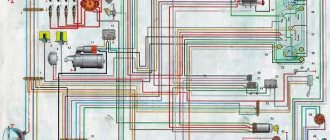
electrical circuit in its simplest form
The good old UAZ-469 is one of the simplest cars. It looks like it was put together from a children's construction kit, there are no frills or decorations here. Instead of air conditioning, there is the ability to remove the soft roof, and instead of power packages, there is a complete absence of anything that could be controlled using the package. However, this car does have an electrical system. Although the same circuit diagram of the UAZ-469 ignition circuit is implemented in the simplest way.
Coil device
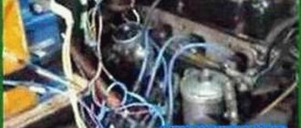
Underwater ignition in a jeep
The ignition coil in the UAZ 469 car has a complex design:
- high voltage screw output;
- output voltage;
- cover;
- contact spring;
- low voltage terminal;
- gasket for sealing;
- mounting bracket;
- magnetic cores;
- contact plate;
- primary winding and secondary winding;
- insulation gaskets;
- Body;
- insulator;
- iron core;
- insulating mass;
- resistor and its insulator;
- Screw and plate for fastening the resistor.
The distributor is designed to distribute and interrupt the ignition timing on a UAZ 469 vehicle. It has vacuum and centrifugal regulators. The centrifugal changes the ignition angle of the UAZ depending on the speed of rotation of the crankshaft or camshaft.
Spark plugs are a very important component. They are used to ignite the working mixture in the combustion chamber in the cylinders and provide a good spark to quickly start the car. The most common spark plugs are A12BS spark plugs, which cannot be disassembled, so in case of failure, you should have new ones in stock that can be quickly and easily replaced.
High-voltage wires are made of PVL-1 wire. They connect the coil to the distributor, and the distributor to the spark plugs. The plugs are attached to the central electrode using special terminals with resistors.
Differences between ignition systems
The main difference between the two systems is the timing of the spark:
- In classic ignition, this is done by a slider under the marker cover, which is in contact with the spark plug wire terminal. In this case, the high-voltage pulse is supplied as a rising pulse. It is, so to speak, lubricated, which reduces the spark strength at the spark plug electrodes.
- With contactless ignition, the switch generates a charge and releases it almost immediately after receiving a signal from the Hall sensor. This allows the spark plug to produce a stronger spark. Among domestic off-road vehicles, such a contactless ignition system is found on the Niva - see the VAZ 21213 wiring diagram.
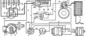
Operating principle of the ignition system
Ensuring and maintaining timely ignition of the air-fuel mixture for the efficient functioning of the internal combustion engine is the main task of ignition. This occurs in strict accordance with the established operating order of the engine cylinders. An ignition coil 16 is connected in series to the electrical circuit along with an additional resistance 14. It is automatically closed when the engine is started by the starter.
This significantly increases the breaking current of the primary circuit. Ignition coil 16 creates high-frequency pulses in the vehicle's on-board electrical system. High voltage flashes create a breakdown of the spark gap in the spark plugs 12, screwed into the top point of each cylinder, where the working fuel mixture is compressed.
The coil consists of primary and secondary windings. The primary winding is wound on top of the secondary. Inside the coil there is a core and a ring magnetic circuit. Both of these elements are made of special electrical steel. Reliable sealing of the coil is carried out by a carbonite cover in a casing with a rubber gasket.
Transformer oil is poured into the casing for cooling. This material significantly increases the insulation of the windings and effectively removes heat from the coil body. To avoid damage to the coil and its overheating, it is not recommended to leave the ignition on in a car when the engine is not running.
Distributor 8 distributes high voltage pulses to all cylinders of the internal combustion engine strictly in the established sequence. The distributor or breaker-distributor is installed in a standard place to the left of the engine cylinder block. The mechanism is driven by the oil pump roller. The roller rotates counterclockwise from the lid side.
Technical characteristics of gasoline engines
| GENERAL INFORMATION |
| Parameter | Engine model | |||
| D.R. | D.S. | NP | W.H. | |
| Number of cylinders | 4 | 4 | 4 | 5 |
| Cylinder diameter, mm | 81,0 | 81,0 | 81,0 | 79,5 |
| Piston stroke, mm | 86,4 | 86,4 | 86,4 | 77,4 |
| Working volume, cm3 | 1781 | 1781 | 1781 | 1921 |
| Compression ratio | 8,8 | 10,0 | 10,0 | 10,0 |
| Rated power, kW (hp)/Crankshaft speed, min–1 | 55 (75)/ 4500 | 60 (90)/ 5200 | 66 (90)/ 5200 | 74 (100)/ 5600 |
| Maximum torque, Nm/Crankshaft speed, min–1 | 138/ 2500 | 145/ 3300 | 150/ 3300 | 150/ 3300 |
| Cylinder operating order | 1–3–4–2 | 1–2–4–5–3 | ||
| Cylinder block | Cast iron sleeveless | |||
| Block head | Made of aluminum alloy, guide bushings and valve seats are pressed into the head | |||
| Pistons | Made of aluminum alloy with steel inserts with two compression rings and one oil scraper ring | |||
| Crankshaft | Forged steel | |||
| Intake valve timing, degrees: | ||||
| – opening to TDC | 5 | 1 | 3 | 0,5 |
| – closing after BDC | 21 | 37 | 33 | 36,5 |
| Exhaust valve timing, degrees: | ||||
| – opening to BDC | 41 | 42 | 41 | 37 |
| – closing after TDC | 3 | 2 | 5 | 1 |
| Gap between the camshaft cams and the valve shims on a cold engine (at a cylinder head temperature of 20° C), mm: | ||||
| – intake valves | 0,2 ± 0,05 | 0,2 ± 0,05* | – | 0,2 ± 0,05 |
| – exhaust valves | 0,4 ± 0,05 | 0,4 ± 0,05 | – | 0,4 ± 0,05 |
| Oil filter | Champions | |||
| Oil pressure in the engine lubrication system, kg/cm2: | ||||
| - idling | 0,3 ± 0,15 | 0,3 ± 0,15 | 0,3 ± 0,15 | From 0.15 to 0.45 |
| at a crankshaft speed of 2000 rpm | 1,8 ± 0,2 | 1,8 ± 0,2 | 1,8 ± 0,2 | 2,0 |
| Air filter | Mann C2852/2 or Purflux A460 | Mann C22117 or Purflux A515 | ||
| Fuel pump | Mechanical diaphragm type brand Pierburg | Mechanical diaphragm type | ||
| Carburetor | Pierburg 1B3 | Pierburg 2E2 | Keihin 26-30DC | Keihin |
| Fuel injection system | – | – | – | – |
| Ignition system | Contactless with distributor sensor, ignition coil and switch | |||
| Ignition timing, degrees | 18 ± 1 | 18 ± 1 | 18 ± 1 | 18 ± 1 |
| Spark plug | Bosch W7D, W7DC, W8D, W8DC; Beru 14-7D, 14-7DU, 14-8D, 14-8DU; Champion N8Y, N10Y | Bosch W6DO, Beru 14-6DU, Champion N79Y | Bosch W6DO, Beru 14-6DU, Champion N79Y | Bosch W6DO, Beru 14-6D, Champion N7Y |
| Gap between spark plug electrodes, mm | 0,6 – 0,8 | 0,8 – 0,9 | 0,8 – 0,9 | 0,8 – 0,9 |
| * For vehicles with automatic transmission. |
| Parameter | Engine model | ||||
| KP | W.C. | KU | RT | NF | |
| Number of cylinders | 5 | 5 | 5 | 5 | 5 |
| Cylinder diameter, mm | 81,0 | 79,5 | 81,0 | 81,0 | 82,5 |
| Piston stroke, mm | 77,4 | 86,4 | 86,4 | 77,4 | 86,4 |
| Working volume, cm3 | 1994 | 2144 | 2226 | 1994 | 2309 |
| Compression ratio | 10,0 | 9,3 | 10,0 | 10,0 | 10,0 |
| Rated power, kW (hp)/Crankshaft speed, min–1 | 85 (115)/ 5200 | 100 (136)/ 5700 | 101 (138)/ 5700 | 85 (115)/ 5200 | 98 (133)/ 5600 |
| Maximum torque, Nm/Crankshaft speed, min–1 | 170/ 3000 | 185/ 4800 | 185/ 3500 | 170/ 3000 | 186/ 4000 |
| Cylinder operating order | 1–2–4–5–3 | ||||
| Cylinder block | Cast iron sleeveless | ||||
| Block head | Made of aluminum alloy, guide bushings and valve seats are pressed into the head | ||||
| Pistons | Made of aluminum alloy with steel inserts with two compression rings and one oil scraper ring | ||||
| Crankshaft | Forged steel | ||||
| Intake valve timing, degrees: | |||||
| – opening to TDC | 1 | 2,5 | 2 | 3,9 | |
| – closing after BDC | 37 | 52,5 | 41 | 31 | 41,2 |
| Exhaust valve timing, degrees: | |||||
| – opening to BDC | 37 | 48 | 40 | 31 | 45,9 |
| – closing after TDC | 1 | 6 | 1 | 2 | 4,9 |
| Gap between the camshaft cams and the valve shims on a cold engine (at a cylinder head temperature of 20° C), mm: | |||||
| – intake valves | – | 0,2 ± 0,05 | – | – | – |
| – exhaust valves | – | 0,4 ± 0,05 | – | – | – |
| Oil filter | Champions | ||||
| Oil pressure in the engine lubrication system, kgf/cm2: | |||||
| - idling | From 0.15 to 0.45 | From 0.15 to 0.45 | From 0.15 to 0.45 | From 0.15 to 0.45 | From 0.15 to 0.45 |
| – at a crankshaft speed of 2000 rpm | 2,0 | 2,0 | 2,0 | 2,0 | 2,0 |
| Air filter | Mann C22117 or Purflux A515 | Bosch | |||
| Fuel pump | Electric submersible type Bosch brand | Electric Bosch | |||
| Carburetor | – | – | – | – | – |
| Fuel injection system | Mechanical system R-Jetronic from Bosch | Mechanical system KE-Jetronic from Bosch | |||
| Ignition system | Contactless with distributor sensor, ignition coil and switch | Electronic type VEZ from Bosch | |||
| Ignition timing, degrees | 18 ± 1 | 18 ± 1 | 18 ± 1 | 18 ± 1 | 15 ± 1 |
| Spark plug | Bosch W6DO, Beru 14-6DU, Champion N79Y | Bosch W6D, W6DO, Beru 14-6DU, Champion N79Y | Bosch W6DC, Beru 14-6DU, Champion N7YС | Bosch W7DTC, Beru 14-7DTU, Champion N7BYC | Bosch W7DTC, Beru 14-7DTU |
| Gap between spark plug electrodes, mm | 0,7 – 0,8 | 0,8 – 0,9 | 0,8 – 0,9 | 0,7 – 0,9 | 0,7 – 0,9 |
In engines of DC type produced since September 1985, NP, KU, NF, hydraulic valve tappets are installed.
How to set the ignition correctly
In order to set the ignition on the UAZ 469, you must adhere to the following recommendations:
- Remove the distributor cover with the rotor. Check the size of the gap between the contacts. It can be adjusted. Between the contacts, separated as much as possible, there should be a gap of 0.35 - 0.45 mm. Adjustment is best done with a set of feeler gauges. Too small a gap produces a weak spark. If the gap is large, there may be no spark at all. Having made a normal gap, the rotor can be installed in its normal place.
- Using a spark plug wrench, unscrew the spark plug of the first cylinder. Close the candle hole with your finger. Using the starting handle, turn the crankshaft until the pin is pushed out by compressed air. This moment is called the beginning of the compression stroke of the first cylinder.
- Continue turning the crank until the hole on the pulley and the pin on the timing gear cover align. The rotor should be located opposite the internal contact of the cover, connected to the high-voltage wire from the spark plug of the first cylinder.
- Rotate the octane corrector plate together with the distributor so that the mark coincides with the middle mark on the scale of the plate.
- Lightly turn the timing mechanism housing counterclockwise. Scroll until the contacts of the distributor close.
- Connect the control light with socket. Connect one contact to the low voltage terminal of the distributor, the second to the ground of the machine. You can connect the warning lamp to the car body.
- Turn on the ignition and carefully turn the distributor clockwise. Rotate until the indicator light comes on, then stop rotating. It may be that the lamp does not light up. Repeat all steps from the very beginning.
- Tighten the distributor mounting bolt. Place the cover with the central wire in place. Check the adjustment starting from the first cylinder. The check is carried out counterclockwise.
The size of thermal gaps
hi-electric.com Hall sensor: how to connect, check or replace, where it is located, principle of operation, signs of malfunction, linear or analog, dual-circuit ignition.
Electronic ignition with hall sensor In the official ZMZ-402 service manual, the thermal clearances of the intake and exhaust valves are defined as 0.40 mm. However, this adjustment is only suitable for Gazelles that constantly carry heavy loads. It is known from experience that reducing the thermal gap to 0.25–0.3 on the intake and exhaust valves allows increasing the throttle response and torque of the engine, as well as reducing fuel consumption. However, this only applies to quiet driving. If you like to drive fast, take off abruptly, or often drive in the mountains, then the clearances must be increased to 0.30–0.35, and in especially severe cases to 0.40.
It is also necessary to increase the gaps to 0.40 if the cylinder head is for 92nd gasoline, and you drive 76th (80th). And vice versa, if the head is for AI-76 (AI-80), and you fill in AI-92. If the cylinder head is for 92 gasoline, and you drive on liquefied natural gas (LNG), then the clearance should be 0.35 for the intake valves and 0.40–0.45 for the exhaust valves. You cannot use gas from a cylinder head for 76-octane gasoline; the pistons and valves will quickly burn out.
Why turn on the ignition?
With the ignition set correctly:
- The engine operates efficiently, steadily and stably in all modes. Otherwise, the engine functions intermittently, knocking, and popping. Unstable engine operation causes many problems and reduces vehicle dynamics and speed characteristics.
- After correct ignition adjustment, starting a cold power unit is significantly improved.
- When the ignition is misregulated, fuel consumption increases. After adjustment it decreases significantly.
- Engine power also increases noticeably in a car after proper ignition adjustment.
Service
How is maintenance carried out correctly on the UMZ 421 engine? According to the factory data and technical maps, we will describe how to carry out maintenance for the 4213. Maintenance of the power unit is carried out every 10 thousand km for operation on gasoline, and 8-9 thousand km - if there is a gas installation:
- TO-0. 1000 km: oil and oil filter change.
- 10,000 km: changing oil, oil and air filters, spark plugs, high-voltage wires, fine fuel filter, adjusting valve clearance.
- 20,000 km: oil change, oil filter, fuel filter.
- 30,000 km: changing oil, oil and air filters, spark plugs, high-voltage wires, fine fuel filter.
- 40,000 km: oil change, oil filter, fuel filter, and generator.
- 50,000 km and beyond: change the oil and oil filter. Every 20,000 km the fuel and air filters are changed and the valves are adjusted.
What are the ignition systems on the UAZ 469
Contact ignition on UAZ 469
. Now it is recognized as obsolete. However, domestic manufacturers continue to use it. The system launches a pulse of a certain power. This impulse comes from the ignition distributor. The contact ignition circuit of the UAZ 469 is simple and uncomplicated. This is its advantage. The driver can fix any malfunction and make adjustments with his own hands. The prices of components are low.
Transistor or contactless ignition of UAZ 469
. Contactless ignition systems are installed on many types of vehicles. It has a number of advantages over the contact design. The spark produced by such a device is much more powerful. This occurs due to an increased level of electrical voltage in the secondary winding of the ignition coil. The transistor ignition system is equipped with an electromagnetic mechanism. It ensures stable, constant operation of the entire system, uninterruptedly transferring energy to components, parts, and mechanisms. Correctly configured ignition with an efficient internal combustion engine guarantees high power and significant fuel savings. Long-term reliable performance is ensured by compliance with the frequency of maintenance of the distributor drive. It must be lubricated and adjusted every 10,000 km. The difficulty of repair is a disadvantage of the contactless ignition system. It cannot be repaired independently, since this requires special diagnostic equipment, available only in service centers and service stations.
Electronic ignition on UAZ 469
. This type of ignition is the most technologically advanced, but at the same time expensive. Modern car models are equipped with similar devices. It has complex technology that provides not only high torque, but also a number of other engine indicators. Advantages: simple adjustment of the advance angle, no mandatory check of contacts for oxidation. In engines equipped with electronic spark protection, the fuel mixture burns 100%. Repairs must be carried out only at a service station.
Underwater ignition on UAZ 469
. This is a sealed ignition system, in which there is no fear of flooding with water, falling into deep holes, or driving in open areas during snow and rain. When the ignition is normal - contact or non-contact, 50% of the spark power is actually lost inside the distributor, between the cover and the runner. Let's find out why this happens.
There is a small gap between the electrical contacts, which are the distributor cap and the slider. To pass electrical energy through this space, most of the additional current is expended. With contact ignition, for these purposes, another part of the energy is spent on the functioning of the cam.
The underwater ignition is designed in such a way that the spark from the coil directly hits the spark plug. Carrying out this process, it does not lose its main power, except for the resistance of high-voltage wires. Here the loss of power is quite insignificant, so it can be ignored.
It is worth noting that on most foreign-made cars, a coil is placed separately on each cylinder, which is located immediately on the spark plug, and the loss is accordingly quite insignificant.
The ignition order on a UAZ depends on the circuit, which has distinctive features for each type of ignition system.
How to set the ignition
In order to correctly adjust and set the ignition on a UAZ, you must follow the sequence of actions that are given in the user's repair manual.
Before you begin adjusting the ignition system, you must place the vehicle on an inspection pit or a special platform for repair work and apply the hand brake. The wheel mechanisms of the vehicle must be secured with a stopper or stop. The power unit must be turned off.
After this, you can begin installing the ignition. To do this, it is necessary to fix the piston of the first cylindrical element in the position of the highest dead center. In this case, you need to check that the hole on the crankshaft pulley coincides with the pin on the cover of the timing gear block. It is necessary to slightly lower the mounting bolt located on the plate to the distribution equipment sensor housing.
Then remove the cover from the distributor and rotate the crankshaft 180°. The octane corrector must be in the zero position. Then it is necessary to tighten the pointer to the housing of the distribution mechanism sensor with a bolt so that its position coincides with the octane corrector mark.
In order to check the ignition coil, you need to turn off the power unit and open the hood. Then you need to find the coil. To do this, it is recommended to follow the wires that lead from the distribution mechanism in the opposite direction. After this, you need to disconnect 1 high-voltage wire from the spark plug. Before the procedure, you must wait until the engine has completely cooled down. This may take 15-25 minutes.
Then you should dismantle the spark plug using a special nozzle. This must be done carefully and make sure that debris does not get into the hole, because. this will lead to malfunction of the power unit. You need to connect the wire back to the spark plug. To perform this operation, it is recommended to use pliers with insulated handles.
After this, you need to touch the threaded side of the candle to the bare metal. When the ignition is turned on, all elements of the vehicle’s electrical equipment will begin to work, which means that the coil is functioning properly. The driver performing repair work should see a blue spark. If it is not there, then the system is faulty. If an orange spark occurs, it means that insufficient voltage is being supplied. This may be due to poor contact, low current, or defects in the coil body.
Another way to check the ignition coil connection:
- Remove the coil from the car. To do this, you need to disconnect the wires of the distribution equipment, remove the fasteners from the coil body using a wrench.
- Determine the condition of the mechanism using an ohmmeter. You need to touch the probes to the primary winding, touching 2 contacts at the same time. After this, it is necessary to measure the condition of the secondary winding and compare the obtained indicators with the factory ones, which are in the repair manual.
Before starting work, it is necessary to place the transport on a flat surface and secure it with special locking devices. When checking the device, it is recommended to wear protective clothing (mask and goggles, as well as gloves).
Site about SUVs UAZ, GAZ, SUV, CUV, crossovers, all-terrain vehicles
On wagon-type vehicles UAZ-374194, UAZ-396294, UAZ-390994, UAZ-220694, UAZ-330394, UAZ-396254, UAZ-330364, UAZ-390944 with the UMZ-4213 Euro-2 and Euro-3 injection engine, the system is installed gasoline injection with microprocessor controlled fuel supply and ignition. With the MIKAS-7.2 control unit for the UMZ-4213 Euro-2 engine and the MIKAS M10.3 unit for the UMZ-4213 Euro-3 engine.
Fuel supply and ignition control system for a UAZ with a UMZ-4213 Euro-2 and Euro-3 engine.
The MIKAS-7.2 or MIKAS M10.3 engine control unit is installed in the vehicle interior, on the right side behind the driver’s seat on the partition. On cars without a partition, the unit is installed in the passenger compartment on the left pillar.
The fuel supply and ignition control system for UAZ wagon-mounted vehicles with a UMZ-4213 Euro-2 engine includes:
- The engine control unit. — Crankshaft position sensor. — Camshaft position sensor. — Throttle position sensor. — Mass air flow sensor. — Air temperature sensor. - Knock sensor. — Exhaust gas oxygen content sensor. — Coolant temperature sensor. — Submersible module with electric fuel pump and fuel level indicator sensor. — Fuel injectors. — Ignition coils. - Spark plug. — Idle speed regulator. — Catalytic converter of exhaust gases.
Schematic diagram of the fuel supply and ignition control system for a UAZ wagon-mounted vehicle with a UMZ-4213 Euro-2 engine.
Location of sensors for the fuel supply and ignition control system on the UMZ-4213 Euro-2 engine.
In more detail, the composition of the fuel supply and ignition control system on UAZ-374194, UAZ-396294, UAZ-390994, UAZ-220694, UAZ-330394, UAZ-396254, UAZ-330364, UAZ-390944 vehicles with the UMZ-4213 Euro-2 engine discussed in a separate article.
The fuel supply and ignition control system on UAZ wagon-mounted vehicles with the UMZ-4213 Euro-3 engine includes the same elements as for Euro-2, with the exception of:
— Instead of a mass air flow sensor, an absolute pressure sensor with a built-in temperature sensor is used. — There is no separate air temperature sensor in the system. — Additionally, the system is equipped with a rough road sensor and a second sensor for oxygen content in the exhaust gases.
Schematic diagram of the fuel supply and ignition control system for a UAZ wagon-mounted vehicle with a UMZ-4213 Euro-3 engine.
How to connect the ignition switch
Replacing the ignition switch involves dismantling the old one and installing a new mechanism with its subsequent connection. To remove the old lock you will need a Phillips and flathead screwdriver.
The procedure for dismantling the old vehicle ignition system lock:
- Remove the fasteners from the lower trim panel of the steering column.
- Insert the key into the lock and set it to the zero position, at which the steering mechanism will be locked.
- Remove the steering column.
- Unscrew the ignition switch mounting bolts.
- Insert a flat-head screwdriver into the small technological hole and press the latch that holds the lock.
- Push the lock out of its seat.
- Disconnect all system wires.
- Install a new lock, connect the wires and reassemble the mechanism, performing all the steps in reverse order.
All wires are connected in a clockwise direction.
To terminal number 50 you need to connect a red wire, which is responsible for the stable operation of the starter device.
To terminal number 15 you must connect a blue wire with a black stripe, which is responsible for heating the vehicle interior.
A pink wire is connected to pin number 30, and a brown wire is connected to 30/1.
The black wire must be connected to the INT connector, which is responsible for the operation of the side lights and headlights.
After all the wires are connected, you need to connect the battery terminal. A black wire should be connected to the top of the terminal. Then you need to start the engine and check the serviceability and functionality of the entire ignition system. First, it is recommended to check the operation of electrical devices, and then the serviceability of the starter mechanism.
If all wires are connected correctly, then when the ignition system key is in the zero position, all elements of electrical equipment will be disconnected from power. When the key is turned to the first position, the system is activated, which controls the internal combustion engine, generator set, headlights and brake lights, as well as washers and windshield wipers. When the key is moved to the second position, the starter is activated, the anti-theft system rod extends and retracts when the key position is changed.
If this does not happen, it means the wires are connected incorrectly. It is necessary to disassemble the mechanism and repeat the connection procedure.
Ignition circuit
The circuit depends on the type of ignition system of the UAZ-3151. In order to correctly set the contact, contactless, electronic or underwater ignition with your own hands, you need to use the repair instructions.
Contact
The contact system connection diagram includes the following elements:
- Lock. It is located on the steering column housing and is necessary to control the flow of current between the vehicle battery and the ignition.
- Battery. At the moment when the engine is turned off, the power source for all electrical equipment is the battery. It supplements the level of electricity produced by the generator set if it produces voltage below 12V.
- Switchgear. It directs high voltage current from the coil through the distributor handle in turn to each of the system's spark plugs.
- Capacitor. It is located on the switchgear housing and prevents the appearance of a spark between the open contacts of the system, protecting them from burning.
- Spark plug. A high voltage current moves along the central electrode of these mechanisms. A spark appears in the gap between the central and side electrodes, which ignites the fuel liquid in the cylindrical device.
- Drive unit. The distribution mechanism is equipped with a direct drive from the camshaft. The rotation speed of such equipment is 50% of the crankshaft speed.
- Centrifugal regulator. It is necessary to set the required ignition timing depending on engine speed. This mechanism includes weights that rotate and act on a plate with breaker contacts.
- Coil. Its design includes 2 insulated winding wires, which are wound on a core made of mild steel. The process of compression of the magnetic fields around the primary winding creates a high voltage current in the secondary winding, passing through the distributor to the spark plugs.
When the driver turns the ignition key, low voltage current from the battery passes to the primary winding of the coil. After this, it begins to form a magnetic field. Due to the rotation of the power unit from the starter, the contacts of the cam interrupter device open. At this moment, the magnetic field begins to disappear, and the power lines and turns of the windings form a high voltage current. The resulting impulse passes to the distributor housing cover, and the spark charge ignites the fuel-air mixture in the cylindrical engine device.
Contactless
In order to establish the contactless ignition timing on a UAZ, you need to prepare the following tools:
- set of wrenches;
- crosshead screwdriver;
- strobe;
- protective clothing in the form of glasses and masks;
- locking mechanisms for wheels.
Before you start connecting, you must put on protective clothing and place the vehicle on a flat surface and secure its wheels using special stoppers.
First you need to put a mark on the valve cover and align all the marks. After this, you should unscrew the spark plug of the first cylinder mechanism of the engine and remove the cover from the main distributor. If you pull out the spark plug of the first cylinder, you can track the stroke of the piston part of the engine.
Then you need to insert a long screwdriver into the spark plug well and turn the crankshaft clockwise by the ratchet, setting it to the highest dead center position. This will help push the screwdriver back out of the well. The mark on the pulley should be placed opposite the long mark on the power unit housing.
After this, you need to loosen the lock nut that presses the distributor to the cylinder block. By rotating the housing, it is necessary to install one of the slots in the gap of the Hall sensor. At this time, the contact of the movable type of the slider must completely coincide with the side contact number 1 on the cover of the distributor, the body of which must be turned to a stable position and secured with a fastening nut.
Then you should tighten the nut securing the distributor and install the cover with the spark plugs in place.
When all the work is completed, you need to start the engine, warm it up to a temperature of +50...+60°C and adjust the non-contact ignition using a strobe light.
The strobe light must be connected to the distributor. It will provide simultaneous flashes with the formation of a spark in the cylinders. By pointing the lamp at the pulley, you can clearly see the position of the pulley mark and its change as the engine speed increases.
When the piston of the first cylindrical mechanism is in the highest dead center position, it is recommended to align the notch of the crankshaft pulley with the first long mark. This risk is located on the cover of the gas distribution mechanism assembly. This will help ensure the required advance angle of fuel injection at the second mark of 5°.
Electronic
In the electronic ignition system there is completely no mechanical movement of elements. The operation of this system is ensured by special sensors and a control unit. This makes it possible to increase the performance of the vehicle’s power unit and reduce the average fuel consumption.
In order to install electronic ignition, it is necessary to move the 4 cylinders of the engine part to the highest dead center position. To do this, you will need to turn the crankshaft ratchet until the marks align with the pulley.
After this, it is necessary to dismantle the distributor, spark plugs and coil, lay new wiring and install a high-voltage coil. Then you can attach the switch to the engine compartment shield and screw in new spark plugs.
High voltage wires must be connected in accordance with the operating order of the cylindrical mechanisms (1-3-4-2).
The brown wire should be connected to connector number 1. To connector number 2 - black. A white wire is connected to connector number 3, and a blue wire is connected to number 4.
In order to set the ignition correctly, you need to prepare a test lamp, a 13mm wrench and a special wrench for the crankshaft. Before starting work, you must turn off the engine and allow it to cool. After this, you need to disconnect the negative terminal of the motor.
Then you need to set the first cylinder to the ignition position. Align the mark on the pulley with the mark on the timing gear drive.
After setting the marks, you can proceed to dismantling the system key. After this, it is necessary to determine the ignition timing. To do this, you need to connect the negative terminal, using a wrench to loosen the fastening nut of the switchgear. Connect one wire of the lamp to the ground of the car, and the second to the low-voltage coil. Turn on the ignition and turn the switchgear housing clockwise until the warning lamp stops lighting.
Starting the engine of any car is possible due to the ignition of the combustible mixture in the cylinders of the power unit. To ensure normal operation of the engine, proper adjustment of the ignition system (IS) is necessary. In addition, all elements, including the coil, distributor of the UAZ vehicle and other components must always be in working order.
Frequency of the procedure
Procedure for removing the cylinder head
Despite its amazing maintainability, the ZMZ-402 was not very successful in its technical characteristics. The lower location of the camshaft, the presence of long pushrods, and the not very high quality of the parts, all this increases the vibration load on the gas distribution mechanism, and therefore reduces the time interval between adjustments. If the motor is used carefully, without operating under maximum load and without sudden starts, then adjustments must be made every 15 thousand kilometers. If the driver likes quick starts, driving at low speeds and high gears, and is also forced to carry heavy loads or drive through the mountains, then the mileage is reduced to 10 thousand kilometers. If you use gasoline that does not match the cylinder head (cylinder head), then, regardless of the ignition settings, the valves must be adjusted after 5–6 thousand kilometers. This will reduce the likelihood of valve burnout and loss of compression.
Description of SZ on UAZ
How is the ignition circuit installed, configured and adjusted on the AUZ 417 or any other? We will talk about this below. But first, let's understand the principle of operation of the node, as well as the types of SZ.
Operating principle of SZ
As already said, the ignition on an UAZ performs one of the main functions when starting the power unit. Thanks to this system, the procedure for igniting the air-fuel mixture in the cylinders of the power unit is carried out by supplying a spark. The spark is directly supplied to the spark plugs; one spark plug is installed on each cylinder. All of these safety devices operate in sequence mode, igniting the combustible mixture in the required period of time. It is also necessary to take into account that the ignition system on cars not only provides a spark, but also determines its strength.
The vehicle battery is not able to produce the voltage and current required to ignite the mixture, since this device only produces a certain amount of current. The help comes from the ignition system, the purpose of which is to increase the power of the car’s battery. As a result of using the SZ battery, it is possible to transmit sufficient voltage to the spark plugs to ignite the mixture.
Types of ignition systems
Today there are three main types of ignition systems that can be installed on cars:
- Contact SZ. It is considered obsolete, but continues to be successfully used on domestically produced vehicles. The principle of operation is that the system produces the necessary impulse, which appears due to the operation of the distribution component. The contact-type device itself is simple, and this is a plus, because in the event of a breakdown, the driver can always diagnose and repair it himself. The cost of replacement components is not high. The main components of a contact type system are a battery, a short circuit, a drive, spark plugs, a capacitor, and a breaker with a distributor.
- A non-contact ignition system called transistor. Many vehicles are equipped with this type. When compared with the type described above, the system is characterized by a number of advantages. Firstly, the generated spark has greater power, which is due to the increased voltage level in the secondary winding of the ignition coil. Secondly, the contactless system is equipped with an electromagnetic device that allows for stable operation, as well as energy transfer to all nodes. As a result, with proper tuning of the internal combustion engine, this allows not only to increase operating power, but also to save fuel. Thirdly, it is convenient in terms of node maintenance. To ensure long-term performance, after setting up and installing the distributor drive, this element must be lubricated from time to time. To ensure normal operation, the element is lubricated every ten thousand kilometers. As for the disadvantages, it is the difficulty of repair. It is impossible to repair the device yourself; this requires special diagnostic equipment, which is only available at service stations.
- Another option for SZ is electronic, which is the most technologically advanced and expensive today, which is why new vehicles are equipped with it. Unlike the two systems described above, the electronic ignition system is characterized by a complex device that ensures the functionality of not only the torque, but also other parameters. Currently, all modern cars are equipped with electronic systems. The key advantage is a more simplified procedure for setting the advance angle, as well as the absence of the need to periodically check the contacts for oxidation. In practice, the air-fuel mixture in engines with electronic combustion almost always burns completely. This type also has its disadvantages, in particular in the matter of repairs. It is impossible to produce it with your own hands, since this requires equipment. Detailed instructions for adjusting the ignition using a light bulb are presented in the video below.
Specifications
The ZMZ 409 Euro 3 engine has improved technical characteristics compared to its older brother.
Thus, the power unit, due to the fact that it was designed on the basis of the 406, received high technical characteristics and endurance. Let's consider the main technical characteristics of the motor:
In addition to the Euro 3 standard, there are a number of modifications that are worth considering:
- ZMZ 409.10 is the main motor, meets the Euro-2 environmental standard. Power 143 hp
- ZMZ 40904.10 - analogue of 409.10 with a new CPG, new gaskets, DBP, complies with the Euro-3 environmental standard. Power 128 hp Installed on Patriot, Hunter, Pickup, Cargo.
- ZMZ 40905.10 - analogue of 40904.10, compliance with the Euro-4 environmental standard. Power 128 hp Installed on Patriot, Hunter, Pickup, Cargo.
- ZMZ 4091.10 - derated low-end version of ZMZ 40904.10, another receiver, camshafts (lift 8, phase 240), firmware, complies with Euro-3 environmental standard. Used on UAZ loaves. Power 112 hp
- ZMZ 40911.10 is an analogue of ZMZ 4091.10, DBP, meets the Euro-4 environmental standard. Used on UAZ loaves. Power 112 hp
- ZMZ 4092.10 is a non-serial motor. Power 160 hp Used on the Volga.
How to set it correctly?
After connection, how is the ignition installed for proper engine operation?
What is the procedure and how to correctly set the node settings, read below:
- To begin, the vehicle must be secured in place, and turn on the handbrake. The piston of the first cylinder must be installed at top dead center; note that the hole on the crankshaft pulley must coincide with the mark located on the timing gear cover.
- The cover must be removed from the switchgear. Having done this, you will see a slider located opposite input 1, inside the cover. If it is not there, then the crankshaft must be turned 180 degrees and the octane corrector set to 0. Using a wrench, screw the pointer to the distributor controller body so that it is aligned with the middle mark on the octane corrector. Loosen the screw securing the plastic to the distribution controller housing a little.
- Carefully turn the housing, holding the slider with your finger so that it does not rotate. This way you can eliminate gaps in the drive. The housing is rotated until the sharp part of the petal on the stator is aligned with the red mark on the rotor. Secure the plate with a screw to the controller body.
- The next step will be to install the controller cover in place and diagnose the high-voltage wires. They must be installed in accordance with the order of operation of the cylinders, that is, first, second, fourth, third. When the ignition timing is set, it is necessary to diagnose the correctness while driving.
- Start the power unit and warm it up for about ten minutes until the temperature is about 80 degrees. Moving on a flat and straight road at a speed of approximately 40 km/h, sharply press the gas pedal. If, when accelerating to 60 km/h, you feel or hear detonation, it should be short-lived, then everything has been done correctly. If the detonation is very strong, then the distribution controller must be turned half or one division counterclockwise. In the complete absence of detonation, the set advance angle should be increased, that is, the controller should be turned clockwise.