- home
- Media center
- Articles
- Ignition order of ZIL-131
Menu
- News
- Articles
- Video materials
- Photo materials
- Publication in the media
- 3D tour
16.12.2020
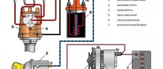
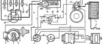
To start and ensure engine operation on the ZIL-131 vehicle, a battery-type ignition system is used. It is used, as a rule, on gasoline power units. Consists of the following components:
- ignition coils, model B 102-B is used;
- ignition distributor devices between cylinders P102;
- directly spark plugs CH307.
The spark plugs, distributor and coil are connected by a thick shielded high-voltage wire. The chopper and ignition distributor are located in one device called a distributor. It has an output shaft with splines, which is connected to the camshaft through a gearbox. The device can be adjusted; accordingly, when installing it, it is necessary to strictly follow the ignition order of the ZIL-131. Otherwise, the engine will malfunction and have obvious power loss.
There is a resistor SE102 in series with the coil in its power supply circuit. Necessary to limit the current during normal operation, that is, the engine is running. When the start occurs and the starter consumes too much energy, a voltage drop from the battery occurs. To do this, the resistor is shunted at this moment to increase it on the coil and ensure normal sparking. The design of the ignition distributor is made hermetically sealed, since a lot of moisture and dirt penetrates under the hood while driving.
The distributor device has a special unit - an octane corrector. By turning the distributor, the ignition timing changes, which allows you to make it earlier or later.
Ignition adjustment
Answering the question of how to set the ignition on a ZIL-131, it is necessary to delve into the design of the device with which you can adjust it. Surprisingly, it is very simple and consists of only a couple of plates. One is fixed to the housing of the distribution device, and the second is statically fixed to the block. By tightening or unscrewing the nuts on the plates, the distributor rotates to a certain angle. It should be rotated within small limits, since the ignition is highly sensitive. The peculiarity of this design is that it can be smoothly adjusted, providing the possibility of the most accurate setting of the advance angle.
The essence of this adjustment is to ensure correct ignition of the fuel-air mixture, which guarantees the necessary force on the piston against fuel detonation at the right moment. The distributor has a removable cover, which provides free access to high-voltage contacts. The middle part of the distributor is also easily removed, which is necessary to provide access to the spark breaker. Sealing gaskets are located between all parts of the shielding housing to ensure the necessary tightness. This is due to the fact that it can work underwater. For normal operation of the breaker, ventilation of the contact area is required. For this purpose, two ventilation hoses are supplied to the housing and connected to the air ducts.
How to set the ignition on ZIL 130
To start and ensure engine operation on the ZIL-131 vehicle, a battery-type ignition system is used. It is used, as a rule, on gasoline power units. Consists of the following components:
- ignition coils, model B 102-B is used;
- ignition distributor devices between cylinders P102;
- directly spark plugs CH307.
The spark plugs, distributor and coil are connected by a thick shielded high-voltage wire. The chopper and ignition distributor are located in one device called a distributor. It has an output shaft with splines, which is connected to the camshaft through a gearbox. The device can be adjusted; accordingly, when installing it, it is necessary to strictly follow the ignition order of the ZIL-131. Otherwise, the engine will malfunction and have obvious power loss.
There is a resistor SE102 in series with the coil in its power supply circuit. Necessary to limit the current during normal operation, that is, the engine is running. When the start occurs and the starter consumes too much energy, a voltage drop from the battery occurs. To do this, the resistor is shunted at this moment to increase it on the coil and ensure normal sparking. The design of the ignition distributor is made hermetically sealed, since a lot of moisture and dirt penetrates under the hood while driving.
The distributor device has a special unit - an octane corrector. By turning the distributor, the ignition timing changes, which allows you to make it earlier or later.
Preparing for adjustment
Due to low-quality fuel, ignition adjustment on the ZIL 131 may be required more than once after repair. So, for example, when using lower quality gasoline with a lower octane number, it is necessary for the spark to occur later, and, conversely, earlier when the fuel has a higher octane number.
The ignition adjustment procedure consists of many stages, because the quality of spark formation is affected by almost all parts in the system:
- Carbon or oxide often occurs at wire connections due to dampness. This leads to a drop in the voltage amplitude and, accordingly, the spark power.
- The spark plug has a gap that should be correct. If there is more, there will be no spark. It should be no more than 0.6 mm and no less than 0.5 mm. By bending the contact you can adjust it to the required size. The stability of the internal combustion engine largely depends on the condition of this part.
- Changing the angle of the ignition distributor, which can achieve high precision ignition of the mixture at the right moment.
- Ignition adjustment is performed by several devices. And it consists of changing the angle by rotating the distributor, changing the spring tension in the breaker, monitoring the gap on the spark plugs and other actions. When performing TO-2 maintenance, it is necessary to check the condition of all elements, lubricate them and adjust the gaps.
Specifications
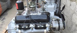
The ZIL 131 engine has a similar design to its older brother 157. The technical characteristics of the 131 have improved significantly, the power has increased, and the design flaws of the past have been corrected.
So, let's look at the technical characteristics of the ZIL 131 engine:
| Name | Specifications |
| Brand | ZIL |
| Model | 131 |
| Engine capacity | 6.0 liters (5969 cc) |
| Engine power | 150 |
| Configuration | V8 |
| Location | Row, longitudinal |
| Consumption | 49.5 liters for every 100 km |
| Number of cylinders | 8 |
| Number of valves | 16 |
| Piston diameter | 100 mm |
| Cooling | Liquid |
| Fuel | Gasoline (gas - as additional equipment) |
| Supply system | Carburetor |
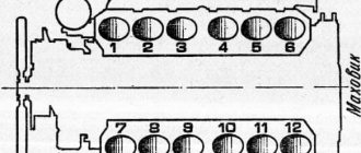
| Cylinder operating order | 1-5-4-2-6-3-7-8 |
| Motor weight | 490 kg |
All ZIL 131 engines were equipped with a 5-speed manual gearbox. Also, the transfer case is two-speed. Gear ratios: 1st gear - 2.08; 2nd gear - 1.00. The main gear of the drive axles is double, the gear ratio is 7.34.
Procedure for performing regulation
Next, we’ll look at how to set the ignition on a ZIL 131 so that the engine provides maximum torque. This operation is usually performed after replacing any system components. And it consists of the following actions:
- First you need to check the size of the gap between the breaker contacts. To do this, you need to smoothly rotate the distributor shaft until the contact pusher rests on the cam. There should be a gap of 0.4 mm between the contacts. It can be checked with a feeler gauge after first releasing the screw on the fixed contact. The gap is set using an eccentric. If there is carbon deposits on the contacts, it should be removed with fine sandpaper.
- It is necessary to check the tightness of the high voltage wire on the cover. This is important, because due to constant sparking, carbon deposits can form, which can cause the spark to disappear altogether.
- When disassembling the distributor, check the condition of all o-rings. If the seal is broken, moisture will penetrate inside, which will subsequently lead to malfunctions of the device.
- If the contacts are normal and the engine is not running stable, then the required stability can be achieved by changing the angle between the contact group and the shaft using adjusting nuts. The angle changes until the engine operates normally without significant detonation or jolting.
Appearance
In ignition systems with a variator, the reason is the low reliability of the latter. As for flirting, I can give you an example from life.
And just imagine this picture of a GAZ, let’s say after a year of production, there is, of course, ignition without an additional resistor. The distributor sensor has a housing, a cover, a roller, a sinusoidal voltage sensor, centrifugal and vacuum regulators, as well as an octane corrector.
Ordinary car wires with a central vein - a spider's web - are no better in this sense. Emergency vibrator fig.
The use of contact-transistor ignition systems makes it possible to: obtain higher output voltages by increasing the current in the primary winding and reduce the electrical load of the breaker contacts; increase the gap between the electrodes of the spark plugs to O.85...1.0 mm, which makes it possible to work on lean working mixtures and thereby reduce the toxicity of exhaust gases; facilitate starting and increase the reliability of engine operation at low and high speeds; increase the durability of the breaker contacts; reduce average operating fuel costs. Powerful ignition for little money Electrics As you know, few people are satisfied with the standard contact ignition of the Urals and Dnieper.
New blog posts
Replace the commutator Naturally, the spark of such coils is two times weaker than the “original” coil. Remove the plastic cover from the distributor sensor. battery; 9.
The distribution among the cylinders is in order. You can check it by connecting a light bulb to it, which will light up when the ignition is turned on. I had to turn it with my “handle” - there were no people willing to “carry” it. At the moment the contacts open, the disappearing magnetic field of the primary winding of the IT transformer penetrates the threads of the secondary winding of the IT and induces an EMF in them, which creates a reverse negative voltage at the emitter junction of the transistor, which contributes to the fastest turn-off of the transistor. In the complete absence of detonation, it is necessary to increase the ignition timing by turning the sensor-distributor housing clockwise.
Candle care
To avoid the need for a new ignition installation on the ZIL 131, it is necessary to follow the maintenance regulations. For example, already during maintenance-1 it is necessary to inspect the spark plugs.
If there is carbon deposits, it should be removed with a fine file or sandpaper. If the gap between the contacts exceeds 0.6 mm, it should be adjusted by bending the outer contact. It is extremely undesirable to touch the central element, as the ceramic insulator is destroyed. The contacts should have a small chamfer so that charged particles can flow off them better when a spark is formed.
During operation, many owners of this car observe a process such as engine “run-down”. It represents the time during which the engine is still running after the ignition is turned off. This is not something abnormal, but quite natural. To fix it, just let the engine idle for a while, and then it will stop as expected. You should do the same thing at the first start after parking, when the internal combustion engine is still cold. While it is warming up, minor misfires may occur, but after heating, operation returns to normal.
Setting TDC at the moment of compression
The problem arises when the piston becomes in the correct position to adjust the valves of the first cylinder. The piston must be at TDC during the compression stroke. There is a mark on the crankshaft pulley. It needs to be aligned with the TDC designation on the scale.
Indeed, the piston of the first cylinder will rise to TDC. But it is necessary to make sure that it is in the compression stroke. Because for the full cycle of engine operation from the first to the eighth cylinder. The piston becomes twice at TDC. We are only interested in one of its positions. This position can be determined in several ways.
- If the engine is in working order on the car. You can remove the tip from the spark plug wire going to the first cylinder. And turn the crankshaft with the ignition on. At the moment a spark jumps between the wire and ground. You should place a mark on the pulley with the TDC designation on the scale. The spark will jump before the piston reaches top dead center. And by setting the marks, the piston will move to the desired position.
- You can unscrew the spark plug of the first cylinder and plug the spark plug hole with a paper plug. When cranking the crankshaft, the plug will shoot out. All that remains is to align the mark on the pulley with the TDC mark on the scale. You can simply plug the hole with your finger. When air starts to come out from under it, all you have to do is align the marks. This indicates that compression is forming in the cylinder. Compression begins. Therefore the valves are completely closed.
- Visually, the TDC position is determined by the rocker arms. In the compression position when the piston approaches TDC, the rocker arms are not movable. The valves are closed. In the second position, when the piston approaches TDC, one valve closes. The second one, after passing TDC, begins to open immediately. If the valves are stationary, all that remains is to align the marks.
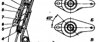
Adjusting valve clearances ZIL-131
Long-term operation of the engine with incorrect clearances can lead to premature wear of valve mechanism parts - burning of valves, wear of rocker arms, bearing surfaces of pushrods and camshaft cams.
If knocking occurs in the valve mechanism, it is necessary to check and, if necessary, adjust the gaps between the valves and rocker arms, which should be within 0.25-0.3 mm (for intake and exhaust valves).
The clearances in the valve mechanism are adjusted on a cold engine using an adjusting screw with a lock nut installed in the short arm of the rocker arm.
To adjust the clearance in the valve mechanism, you need to set the piston of the first cylinder to the top dead center (TDC) of the compression stroke.
In this case, the hole on the crankshaft pulley should be located under the “TDC” mark on the ignition timing indicator located on the maximum speed limiter sensor.
In this position, it is necessary to adjust the clearance of the following valves;
- intake and exhaust first cylinder
— exhaust second cylinder
The clearances of the remaining valves must be adjusted after turning the crankshaft 360° (full rotation).