Front steered axle
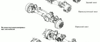
Depending on the purpose and assigned functions, bridges can be driven, steered, combined or supporting. A driving axle is a bridge whose wheels receive torque from the engine through transmission mechanisms. A steering axle is designed to support the vehicle and ensure its maneuverability. The wheels of this bridge do not accept torque and are driven. The combined axle is both driven and steered, i.e. it receives torque and at the same time serves to perform turns and other vehicle maneuvers. A trailing axle is designed solely to support the vehicle and is not capable of providing wheel traction or turning the vehicle.
***
Front steering axle device
The front steered axle is a transverse beam with driven steered wheels. The front steering axle beam is usually made of forged steel and has a spatial section to increase bending strength. Depending on the type of suspension of the steered wheels, the front axles of cars can be continuous, in which the steered wheels are connected directly to the bridge beam, and split, in which the steered wheels are connected to the bridge beam through the suspension.
The schematic structure of the most common types of steered front axles is shown in Fig. 1.
The front continuous steering axle (Fig. 1, a) is made, as a rule, in the form of a forged steel beam 4 of I-section. At the ends of the beam, pins 3 are fixed in the bosses, and at their outer ends, pivot pins 2 are hinged, on which the wheels are mounted by means of bearings. The axles can rotate around their kingpins along with the steered wheels, allowing the vehicle to turn. The connection between the bridge beam and the frame is carried out through suspension elements - springs, springs, shock absorbers, pneumatic cylinders, etc.
The front split steer axle (Fig. 1, b) differs from a continuous axle in that its transverse beam 4 is connected to the steered wheels by means of independent suspension arms 7. In this case, the bridge beam is connected to the supporting system (most often the body) of the vehicle rigidly and simultaneously serves to accommodate engine mounts. Steered wheels with hubs, mounted by means of bearings on swivel axles, can rotate around king pins or ball joints of the suspension, or together with struts (pinless suspensions).
Front continuous steered axle
In Fig. 2 shows the front steered continuous axle of a GAZ truck. A steel I-beam 14 s is attached to the car frame by means of two springs.
The middle part of the beam is curved down, which allows the engine to be positioned lower and optimizes the layout of the vehicle's cabin. In the end bosses of the beam, pins 8 are fixed by means of stoppers 12, and a rotary axle 7 is attached to them through bronze bushings. Shields 6 of the brake mechanisms are fixed to the flanges of the rotary axles, and hubs 3 are installed on the axles of the axles on tapered bearings. Wheels 1 are mounted on the hubs with brake drums 2 can rotate on bearings together with the hubs around the axes of the pivot pins 7 and, together with the pivot pins, rotate around the pivot pins 8.
Front split steer axle
In Fig. Figure 3 shows a split front steering axle of a passenger car with an independent pinless lever-spring suspension. The main part of the bridge is the transverse beam 4. The front steered wheels of the car are suspended from it by means of the upper 3 and lower 5 levers of the rotary struts 2, springs 6 and shock absorbers 7. The wheels, together with hubs 9 and brake discs 8, are mounted on bearings on swivel stands 2, to which the wheel brake calipers 1 are attached. The steered wheels turn together with the steering struts, changing the direction of the vehicle when maneuvering.
The split steered front axle of a passenger car is removable and is rigidly bolted to the supporting body of the car. The bridge beam simultaneously serves to mount the engine using elastic elements (engine mounts).
***
Center differential
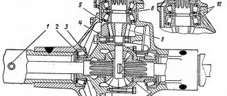
To distribute torque evenly between the two drive axles and reduce tire wear, a center differential is used, which is installed in the middle (intermediate) axle in a separate housing 13 (Fig. 8), attached to the main gear housing through the bearing housing of the drive bevel gear. The housing contains the rear 10 and front 11 cups, bevel gears 12 and 14 for driving the middle and rear axles, respectively, between which there is a cross 16 with satellites 15 mounted on it on bronze bushings.
The differential locking mechanism is also located here, consisting of a locking clutch 9, a fork 8 and a diaphragm chamber 6. Clutch 9 is placed on an internal gear coupling, rigidly connected to the bevel gear 12 of the middle axle main gear drive.
[custom_ads_shortcode1]
Support bridge
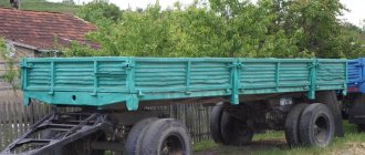
The support bridge (Fig. 4) serves only to support the vehicle's supporting system. It is used as a rear axle in front-wheel drive passenger cars, as well as on trailers and semi-trailers.
The main part of the bridge is a U-shaped steel beam 5 with tubular arms 3 and spring suspension 4 welded at the ends. Axles 1 are attached to the ends of the arms, on which hubs 2 with rear supporting wheels are mounted by means of bearings. The other ends of the levers are pivotally connected to the car body.
The support axles of heavy-duty vehicles, trailers and semi-trailers can be lifting - when the vehicle is fully loaded, they are lowered into the working position and support the weight of the vehicle or trailer (semi-trailer), and when an empty road train is moving, they can be raised together with the wheels into the transport position without providing additional resistance rolling, which improves fuel efficiency and reduces tire wear. Typically, one of the double axles of the rear bogie is used as a lifting axle. The lifting mechanism of the supporting axle is most often controlled by hydraulic, pneumatic or mechanical drives.
***
Combined bridges
Home page
- Applicant's page
Distance education
- Group TO-81
- Group M-81
- Group TO-71
Specialties
- Veterinary
- Agricultural mechanization
- Commerce
- Vehicle maintenance and repair
Academic disciplines
- Engineering graphics
- MDK.01.01. "Car design"
- Section map
- General structure of the car
- car engine
- Car transmission
- Steering
- Brake system
- Suspension
- Wheels
- Body
- Car electrical equipment
- Basic car theory
- Basics of technical diagnostics
- Fundamentals of hydraulics and heat engineering
- Metrology and standardization
- Agreecultural machines. Agreecultural equipment
- Basics of agronomy
- Transportation of dangerous goods
- Materials Science
- Management
- Technical mechanics
- Tips for graduate student
Maintenance, troubleshooting and repairs
Maintenance of the unit is carried out with general maintenance of the tractor transmission, which consists of checking the tightness of all joints of the system housings and monitoring the oil level. Seasonal oil changes are carried out with a lubricant of the appropriate viscosity when the temperature drops below +5°C. The viscosity indicator is important for the trouble-free operation of the automatic switching mode, since when the temperature drops, thickened summer oil will interfere with the operation of the overrunning mechanism of the transfer case.
Automatic mode does not work
The causes of this problem may be contamination of the running channels of the profile grooves of the gear with dirt and metal oxidation products. And also due to shrinkage of the mechanism springs, unacceptable wear of the rollers and running channels with grooves, and wear-out of the driven part of the coupling.
Often the cause of failures is the appearance of edges on worn rollers. In this case, they are replaced with rollers with an increased repair size to compensate for the increased worn jamming grooves of the mechanism. The first set of rollers have a diameter of 15 -0.012 mm, the repair rollers have a diameter of 15.15 -0.012 mm.
FDA drive does not work
The main cause of the problem is the appearance of unacceptable axial play as a result of wear of the bearings, as well as the bushing on which the driven part of the coupling is mounted. Axial vibration disengages the forced engagement gear coupling, preventing rotation from being transmitted to the drive. To eliminate it, the unit is dismantled, completely disassembled, troubleshooting and replacement of failed parts is carried out.
An additional reason for poor activation of modes is a violation of the adjustment of the switching mechanism as a result of shrinkage of the shock absorbers in the cab mount and a slight change in its position relative to the tractor frame. The unstable position of the fixing post and rod disrupts the amplitude of travel of the levers of the activation mechanism. For normal operation, it is periodically necessary to check the compliance of the positions of the switching modes and make adjustments by changing the length of the rod using a threaded coupling.
Often, malfunctions in the operation of the transfer case occur as a result of a complex of reasons - general wear and contamination of the mechanism, incorrect adjustment of the activation mechanism. If we talk about disruption of the rotation transmission from the transfer case to the FDA, you need to pay attention to the adjustment and technical condition of the intermediate drive support.
In conclusion, it should be noted that the working life and normal operation of the unit are directly affected by the condition of the joints of the cardan drive, the intermediate drive support, and the final drive of the front axle. If unacceptable axial clearances appear in the rotation bearings of the FDA drive units, axial runout will break the bearings in the shaft supports and the transfer case coupling, which will lead to axial instability of the unit parts and, as a consequence, to the impossibility of switching on the drive operating modes or complete failure. Therefore, when repairing any FDA drive unit, pay attention and check the technical condition of all parts, starting with the FDA main drive and ending with the transfer case. This will extend the service life of all drive components and parts, have a positive effect on technical readiness for work, and reduce the cost of maintaining the tractor.
Repair and adjustment
If a malfunction in the operation of the support is detected, it is recommended to disable the front axle drive. In compliance with safety regulations, inspect the unit and check the lubricant level in the housing. If there is a working oil level and there are no unacceptable backlashes on the seats of the connecting flanges of the unit, tighten the adjusting nut 2 with a force of 40 N.m (4 kgf.m.) to achieve an increase in the clutch actuation force to 400-800 N.m (40-80 kgf. .m).
If the adjustment does not give a positive effect in the operation of the unit, it is dismantled to inspect the unit and troubleshoot problems. When performing an inspection, if the assembly parts are in normal condition, the reason for the lack of the set clutch actuation force is the wear of the friction discs. Fix the problem by additionally installing a pair of working disks and, if necessary, change the spring disc washers. Thus, the wear thickness of the discs is compensated and the required force when tightening the adjusting nut is restored.
Also, during subsequent repairs, it must be taken into account that due to heating of the oil, rubber seals lose their elasticity and, although visually intact, do not perform their sealing function.
The procedure for assembling the intermediate support
Before starting assembly, make sure that there is no unacceptable wear on the parts' seats. The presence of ellipse in the seating areas of the intermediate sleeve, support sleeve, sliding and connecting flanges will cause imbalance during rotation and will not allow the seals to fit tightly in the assembly structure.
The assembly of the unit is carried out in the following order:
- seating the oil seal in the support body
- seating bearings on intermediate sleeve
- fit into the intermediate sleeve of the supporting sleeve of the connecting flange
- Fitting the bushing with bearings into the unit body, assembling the coupling parts onto the shaft
- installing the coupling on the internal splines of the intermediate sleeve
- installing a sliding flange on the intermediate sleeve splines
- installation of seals on the side of the connecting flange
- installing sealing gaskets under the unit covers and tightening them
- adjusting tightening of the coupling cotter pin nut with a force of 40 N.m
When assembling, make sure that the installed parts take their place without distortion.
Assembly procedure for the promo-pore coupling
The sequential installation of parts on the coupling shaft is carried out in the following order:
- installing a spacer sleeve on the shaft
- behind it, a reinforced drive clutch disk and a complete set of clutch disks are installed (alternately leading - driven)
- at the end of the set a reinforced disk is also installed
- then install pairs of spring disc washers
The correct assembly of coupling parts is checked by the presence of a compression effect on the discs when tightening the coupling nut on top of the installed connecting flange.
The number of disks in the coupling can be different and depends on the working thickness of the disks included in the assembly. The set of disks must correspond to a size that allows, in the assembled state, to provide a supply of the threaded part of the shaft shank for the required tightening force.
Types of axle units by number of wheel pairs:
- Single pair. Each hub is equipped with one regular wheel. The design is designed for small and medium loads and is highly maneuverable.
- Twin. Wheels are mounted in pairs on the hubs. Mostly such designs are intended for rear axles of freight vehicles.
Axles are important elements of the running system of self-propelled and trailed mechanisms. They provide connection to the wheels, absorb motor loads, and distribute forces to the chassis structure through suspensions. The versatility and versatility of automobile bridges makes it possible to create vehicles with various functional capabilities.


