Bleeding the MAZ clutch
Bleeding the clutch means that all air will be removed from the clutch mechanism.
Before removing air from the system, it is necessary to adjust the mechanism to ensure freedom of movement of the gear lever. The pumping process itself is as follows: First, it is necessary to replenish the lost liquid in the main barrel to a level of one and a half to two centimeters from the edge. The liquid is topped up with mandatory filtration to prevent excess impurities from entering the system.
Then, it is necessary to remove the rubber cap of the PSU from the valve, which provides bypass. In the future, you need to put a hose on it. The opposite end of the hose must be lowered into a half-liter container filled with brake fluid one third of the way.
It is very important to immediately use the liquid that will later be used in the system
After which you can begin to “bleed” the clutch, having first unscrewed the bypass valve one turn. This operation requires two people: the first will bleed the clutch until air bubbles stop coming from the hose. The second is to control the air removal process and monitor the liquid level; it should not be lower than three and a half centimeters from the edge. If the fluid level begins to drop, it must be topped up.
To speed up the process of bleeding the clutch, there is a popular trick - turning the bypass valve after each press on the clutch pedal. After which, the pedal goes down and up again. Typically, three presses are enough to remove air from the system, provided the valve is rotated correctly.
At this point, the bleeding process is completed; it is necessary to reassemble the mechanism in the reverse order, removing the hose and putting the protective cap back on. In the process of removing air, the liquid will still leave, so its level must be increased to its original state - one and a half to two centimeters from the edge.
Having assembled the clutch mechanism to its original state, it is necessary to check its operation. This is done by pressing the clutch pedal all the way, while simultaneously checking the piston pusher. If its stroke is approximately twenty-seven to twenty-eight centimeters, then the pumping can be considered successful. If the stroke is different, the clutch must be adjusted again.
4370-1601203-060
New model MAZ-4370 clutch release fork (petal clutch) In stock Price in Euro: 0.00
Price: 3920 rub.
Clutch MAZ KPP-202 (2-disc clutch) To order Price in Euro: 0.00
Price: 7500 rub.
184-1601180 KPP-202
Clutch MAZ-543205 (Yaroslavl leaf clutch) To order Price in Euro: 0.00
Price: 2390 rub.
HAMMER
Clutch assembly MAZ-4370 KPP-433420 (k130512+d100331+m202001) In stock Price in Euro: 0.00
Price: 32800 rub.
HAMMER 3482083032 (k/d/v)
Clutch assembly MAZ-5440,6430 with (Shaanxi/ZF gearbox) To order Price in Euro: 0.00
Price: 43,500 rub.
3482083032/1878004832/315
Clutch assembly MAZ-5440,6430 SHAFT In stock Price in Euro: 0.00
Price: 29890 rub.
3482083032/1878000206/315
Clutch KAMAZ 65115 assembled (disc/basket/releaser) To order Price in Euro: 0.00
Price: 16250 rub.
4308-1600008
Clutch KAMAZ-4308,65115 door CUMMINS d-y395 In stock Price in Euro: 0.00
Price: 24950 rub.
Pumping the node
To bleed the clutch, you need to fill the hydraulic reservoir with water, this should be done gradually to a level of 1-1.5 cm. It is necessary to clean the cylinder exhaust valve, it is dirty. It is necessary to remove the special cap from its head and install a rubber hose on the cylinder. Now the end of the hose must be inserted into the hydraulic fluid, which is poured halfway into a liter jar. To pump the clutch, you need to slowly press the pedal of the unit at intervals of 1-2 seconds. You need to press about 4-5 times. Without strict adherence to all points of the instructions, the result may be zero, so you must be careful when bleeding the clutch.
How to upgrade
Pumping of the CCGT unit at MAZ is carried out as follows:
- Make a homemade pressure device from a plastic bottle with a capacity of 0.5-1.0 liters. Holes are drilled in the lid and bottom, into which nipples from tubeless tires are then installed.
- It is necessary to remove the spool valve from the part mounted in the bottom of the container.
- Fill the bottle 60-70% with fresh brake fluid. When filling, close the hole in the valve.
- Connect the container with a hose to the fitting installed on the amplifier. A valve without a spool is used for connection. Before installing the line, you need to remove the protective element and loosen the fitting by turning 1-2 turns.
- Apply compressed air to the bottle through the valve installed in the cap. The gas source can be a compressor with a tire inflation gun. The pressure gauge installed on the unit allows you to control the pressure in the container, which should be within 3-4 kgf/cm².
- Under the influence of air pressure, liquid enters the cavities of the amplifier and displaces the air present inside.
- The procedure continues until the air bubbles in the expansion tank disappear.
- After filling the lines, it is necessary to tighten the fitting and bring the liquid level in the tank to the required value. A level located 10-15 mm below the edge of the filler neck is considered normal.
The reverse pumping method is allowed, when the liquid is supplied under pressure into the tank. Filling continues until gas bubbles stop coming out of the fitting (previously unscrewed by 1-2 turns). After filling, the valve is tightened and closed on top with a protective rubber element.
Read more: Stickers for the dashboard of the VAZ 2107
After bleeding the PSU clutch, it is recommended to check the condition of the rods, which should not be deformed. Additionally, the position of the brake lining wear sensor is checked, the rod of which should not protrude beyond the pneumatic cylinder body by more than 23 mm.
After this, you need to check the operation of the amplifier on a truck with the engine running. If there is pressure in the car's pneumatic system, it is necessary to press the pedal all the way down and check the ease of gear shifting. Gears should shift easily and without extraneous noise. When installing a box with a divider, you need to check the operation of the unit drive. In case of incorrect operation, the position of the control bracket must be adjusted.
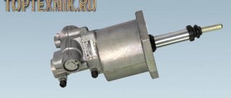
As in any other car that uses a similar device, the main task of the MAZ clutch PGU is to make life easier for the driver, and more specifically, the pneumatic-hydraulic booster makes it so that the driver has to spend less effort when squeezing the clutch pedal. And for heavy vehicles, such relief is very useful.
Let's look at the example of the PGU MAZ 4370 clutch design and other MAZ models. The principle of operation is as follows - pressing the pedal causes an increase in pressure on the hydraulic piston, and the same pressure is experienced by the follower piston. As soon as this happens, the automatic tracking device turns on and changes the pressure level in the power pneumatic cylinder. The device itself is attached to the crankcase flange.
There are quite a few options for amplifiers, but speaking specifically about Minsk trucks, most of them have one not very pleasant feature in common - it often happens that during operation, liquid begins to leak from the CCGT unit. Naturally, the first thought that comes to mind is that this may be a sign of a breakdown that occurred due to overload, and a serious one at that.
Consultation on technical issues, purchase of spare parts 8-916-161-01-97 Sergey Nikolaevich
But jokes aside, especially since leakage of fluid from a pneumatic-hydraulic booster is a serious symptom. In fact, everything is not so tragic; the fact is that this may not be evidence of a breakdown, but just an incorrect adjustment. “Only”, because repairing a MAZ clutch PGU is not complicated and, with certain skills, will not take much time.
If this distance is less than 50 mm, then this means that during operation the rod plunger will extend all the way, thereby opening the outlet of the liquid. All that is required is to move the lever one slot closer to the amplifier. If the distance is greater, then the reason for the leakage is different, and it is better to carry out a more detailed check at a car service center. However, we repeat, but most often there will be plenty of adjustment.
Design and principles of operation
The design of the coupling mechanism includes such elements as:
- flywheel;
- hydraulic power steering;
- overlays;
- a spring device that presses the disk against the flywheel housing;
- clutch release fork, clutch release drive;
- push-type coupling;
- coupling pedal shaft;
- pressure disk;
- double-disc or single-disc petal device;
- release bearing;
- protective casing;
- transmission drive shaft.
- When the driver presses the pedal, the shaft begins to rotate.
- A gap forms between the fork and the push-type coupling.
- The clutch, together with the bearing, begins to move, causing the bearing to exert pressure on the inner ring of the handle.
- The handle moves the pressure plate away from the driven disc.
- The spring mechanism is compressed, causing the disk to move towards the flywheel of the power unit.
- The splines of the driven disk move to the splines of the gearbox input shaft.
MAZ clutch single-disc petal device installation. MAZ clutch repair
MAZ, what components this element includes. Today “AvtoResurs” will tell you in detail how to repair a MAZ clutch. Practical advice and photos of replacing a MAZ clutch will help in repairing a modern truck.
MAZ clutch repair - where to start?
Adjusting the MAZ clutch is much more difficult than repairing the element. We will touch on the nuances of adjustment in the following articles. Now let’s study how to replace the MAZ clutch. Before you start repairing a MAZ spare part, we advise you to think about the causes of the breakdown. The MAZ clutch can fail due to the failure of the driven disk, and due to wear of the bearings, springs and seals. As a result, you may notice that the truck:
- Makes sudden jerks during winding.
- Makes noise when the pedal is pressed and a burning smell.
- Has a discrepancy between acceleration and revolution.
Another reason for MAZ clutch failure is that it is very difficult to change gears. These wear symptoms can be eliminated by adjusting the clutch. The very first thing we do is check the CCGT. Press the clutch pedal
Pay attention to the PSU rod. If this element has a stroke, that is, it gradually squeezes out the fork with release - the spare part is in good condition and does not require replacement
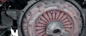
MAZ clutch repair has several stages. After checking the PSU, we look at the clutch casing. Ideally, it should not contain any oil leaks. In some cases, the clutch may “slip” due to excess oil. Let's look and eliminate the reasons. If the car, even after removing the oil and checking the PSU, is not working properly, we will repair the clutch further. Replacing the clutch MAZ - remove the gearbox Failure of the element in question is possible due to failure of the clutch disc, basket and bearing (release). Sometimes discs are filled with oil. However, you can understand why the clutch slips, why the clutch is tight, only after disassembling the gearbox. Therefore, we remove the gearbox and continue repairing the MAZ clutch. I recommend replacing several MAZ spare parts along the way, which, in principle, do not affect clutch failure.
The fact is that in most cases the elements have significant signs of wear, which will lead to breakdown over time. Moreover, if you are repairing a MAZ clutch, it means that the box has not been removed for at least a year. Therefore, some consumables will actually have to be replaced. Replacing a MAZ clutch most often includes purchasing a new one:
- Clutch disc.
- Release bearing hose.
- Release bearing.
- Gearbox input shaft oil seal.
- Bearing spring.
- Gaskets for oil pump and shaft.
Only after purchasing new parts do I recommend repairing the MAZ clutch. Replacing the dump truck clutch First, raise the body. Don't forget to lock it in this position. This way, replacing the clutch will not harm you. In general, follow basic safety precautions. Then gradually drain the oil from the gearbox. We disconnect such elements as the body lift pump, cardan and tubes. Repairing the MAZ clutch also requires removing the yoke with the rear support pad, the PGU and its bracket. Let me emphasize - ALWAYS remove the bracket! Adjusting the MAZ clutch, most often, if the bracket is not removed, can lead to breakage of the release bearing fork and its spring.
After this, inspect the condition of the release bearing and gearbox basket. If you do not find any signs of wear on these elements, adjust the clutch further. Therefore, we remove the basket from the car flywheel. This will give us access to the clutch disc. We examine d
How to repair a clutch
There is no need to replace the linings frequently; you can simply carry out adjustment work on the clutch. Instead of replacing the linings, you can adjust the entire assembly, which consists of thrust bars, rods, and rings.
This work must be carried out according to the instructions.
The fact is that when the linings wear out, the pressure-type disk moves. It moves towards the flywheel and the split rings themselves move towards the casing along the rod. As a result of the adjustment, it is possible to return the original clearances, thereby extending the service life of the linings.
MAZ clutch and part device
The MAZ clutch is a double-disc friction type device. It has springs that are located peripherally. The MAZ clutch device also includes discs. The elements are made of durable materials. The MAZ clutch is installed in a crankcase made of strong cast iron. The leading parts of the mechanism are the MAZ clutch disc (middle and pressure) and the MAZ flywheel. AvtoResurs LLC offers a closer look in a number of articles on how to adjust the MAZ clutch and repair the part. However, today we will tell you what the MAZ clutch device consists of and how the MAZ clutch drive works.
1. The MAZ clutch has a complex structure
Let's look at the Minsk Automobile Plant truck model 5335. Let's carefully study the MAZ clutch design. So, the mechanism includes a huge number of elements, for example:
These components are the main ones in the design of MAZ spare parts. Also, all mechanisms are strong and resistant to heavy loads. Therefore, the MAZ clutch, as well as the MAZ clutch drive, last a long time and rarely fail. Cast iron is mainly used for the manufacture of elements from the MAZ clutch device. Let's take a closer look at each part of the part being studied. The MAZ clutch disc (pressure and drive) is cast from durable cast iron.
Has spikes that attach to the truck's flywheel. Thus, the MAZ clutch is a very strong connection, which makes it easy to move the MAZ clutch disc. Also in this case, torque is transmitted to an element such as the MAZ clutch disc from the flywheel. A frictional force arises. The MAZ clutch has several friction attachments that contain the MAZ clutch disc. Therefore, during the operation of the elements, a frictional force occurs.
2. MAZ clutch is reliable and strong
We continue to consider the MAZ clutch device.
To prevent heating of the springs, which most often occurs when the truck slips for a long time, a pressed cardboard gasket is adjusted under the springs of the MAZ spare parts. The MAZ clutch disc is not interchangeable. The elements are mounted on the MAZ input shaft, that is, on its splines. The MAZ clutch also includes a hub, a disc with linings and a vibration damper.
As a rule, MAZ hubs and MAZ clutch discs are made of steel. The MAZ clutch is protected from the harmful effects of various vibrations when the vehicle is moving thanks to a special damper. These vibrations are most often transmitted from the truck engine shaft. In addition, the MAZ clutch device is reliably protected by a failure absorber when the mechanism is engaged. The damper also allows the gearbox gears to operate more smoothly.
The MAZ clutch disc is not included in the drive to disable the mechanism in question. So the MAZ clutch device when turned off is approximately the following:
Thus, the MAZ clutch drive is equipped with a pneumatic booster. In general, the part is strong and practically does not break. However, the MAZ clutch drive, like any element of a truck, requires regular inspection. The rods and valves are connected in series. Thus, the mechanical clutch drive is also equipped with a working cylinder of the amplifier. The element is installed in parallel. The MAZ clutch drive includes in its MAZ clutch device and a double-arm lever, which is connected to the cylinder and valve rod.
That is, by adjusting the free play of the MAZ clutch pedal. In addition, the MAZ clutch drive is regulated by the gap between the ring (retaining ring) and the end of the valve body cover. The MAZ clutch disc does not require special care.
Inspect the part regularly to ensure timely repair of breakdowns. The MAZ clutch drive is also unpretentious.
Just periodically check the free play of the pedal and clutch bearing.
The MAZ clutch device also contains a drive. We recommend that you monitor the condition of this item more carefully. Subscribe to our channels on social networks twitter, facebook, contact, google+.
How to make adjustments
To adjust the MAZ clutch, you should set aside some time. First you need to dismantle the flywheel crater, which is located on the manhole cover. This is necessary to free up the middle disk. We then proceed according to the following principles:
- The clutch is completely disengaged;
- The gear lever is set to the neutral position;
- The engine flywheel turns;
- The locknuts of the screws are unscrewed;
- Four screws go into the middle type drive plate.
After this, you need to continue rotating the flywheel, before which you need to unscrew the screws once. After going through these steps, you need to secure the screws with locknuts. During the entire work process, you should hold the screw with a special tool, this will make it possible to maintain the adjusted gap.
MAZ double-disc clutch
Next, you need to measure the gap between the end and the nut on the rear valve cover. This parameter of a device such as a double-disc clutch should be equal to 3.3 mm, and it must be adjusted precisely to this indicator. In order to complete the adjustment, you need to loosen the lock nut and bring the gap to the desired value. After the result is achieved, you need to tighten the fasteners and check their reliability.
Bleeding the clutch
Many MAZ owners are well aware of the problems that may arise during the operation of the car. Among such problems, air getting inside the hydraulic element of the clutch assembly is quite common.
Among the reasons leading to such trouble are:
- pipe damage;
- loose tightening of certain parts.
There is a sequence of actions that can be used to bleed the MAZ clutch and restore or even improve the performance of the entire unit.
Materials and tools
Before you begin, you should prepare the necessary tools and materials. The main equipment that may be required during repairs includes:
- Brake fluid. It is recommended to be as careful as possible when using this liquid, as its composition is poisonous.
- A set of tools that every driver has.
- A container in which you will need to pour out the brake fluid.
- Hose. The diameter of the hose must match the diameter of the drain hole.
You will also need to find an assistant, since it will be almost impossible to cope with the task alone. In addition, it will be much more convenient to pump the clutch with two or even three people. If you cannot find an assistant, then it is recommended to find a suitable device with which you can fix the clutch pedal. Such a device can be a rail or, for example, a stick made of wood or metal.
Step-by-step instruction
Many people wonder how to upgrade the PGU in MAZ? Removing air and pumping the hydraulic drive is carried out in several stages. Each of them represents the following actions:
- First of all, the car owner will need to remove the plug that is installed on the tank. This is done so that brake fluid can subsequently be poured inside to a level of 1.5 cm above the boundaries of the container lid.
- Next, you need to dismantle the cap located in the place where the bypass valve is located. When the action is completed, you need to connect a hose to the valve head and then insert the other end of this hose into the container where the brake fluid is filled.
- The third step is to unscrew the bypass valve either half a turn or a full turn. Further, the operating principle is simple. The car owner will then need to press the pedal as sharply as possible so that it quickly hits the limiter. This must be done in such a way that the release of air bubbles formed inside the liquid is stopped.
- During the pumping process, you should add liquid inside the tank, while making sure that the volume does not decrease and does not rise above 4 cm to the edge of the upper border of the neck of the container.
- When the pumping is completed, you should screw the bypass valve all the way, without releasing the pedal that is pressed all the way, and also remove the hose and return the cap to its place, fixing its position.
Completion of pumping implies another injection of liquid into the tank in order to achieve the optimal volume and continue operation of the vehicle.
You can evaluate the success of the completed task by how the pusher of the pneumatic amplifier works. If full travel has been achieved, the job has been done correctly. The same can be demonstrated by the liquid inside the main cylinder, which does not contain air and is in the optimal volume during the movement of the car and the operation of the clutch.
Service
Maintenance of this mechanism is carried out as follows:
- Carry out an external inspection of the pedal and, if necessary, adjust its free play.
- Bleed the hydraulic drive.
- Carry out diagnostics of the crankcase fastening elements and, if necessary, tighten the nuts.
- Carry out an external inspection of the tension spring device, lubricate the bearings and hydraulic coupling.
- Check the functionality of the clutch switch and the shaft sleeve.
- Inspect the fork and clutch pedal for wear and damage.
- Check the operation of the mechanism by changing the gears of the vehicle on the spot and during acceleration.
- Eliminate incorrectly set gaps between support rings and washers.
- Eliminate leaks in the system and lubricate all cylindrical elements with a special liquid.
- Check the gap between the rods and the piston part of the main cylindrical device.
How to make adjustments
Actions when adjusting the MAZ clutch:
- Adjust pedal free play. To do this, you need to put your foot on the pedal and squeeze the gas all the way. If necessary, reduce or increase the stroke of this device.
- Release the pedal and measure the distance to the lower mark of the coupling mechanism.
- The maximum stroke amplitude should not exceed 16 cm.
- Tighten all fasteners.
- Measure the pedal free play.
After the driver has adjusted the clutch mechanism, it is necessary to adjust the MAZ clutch basket:
- Place the transport on a special platform.
- Unscrew the mounting bolts that connect the gearbox and the car body.
- Remove the gearbox.
- Unscrew the screws of the push-type disk and remove it.
- Inspect the basket and replace damaged or worn parts.
- Adjust the position of the paws.
- Using the adjustment handle, set the paws to the positions shown in the MAZ repair manual.
- Tighten all mounting screws until they are secure.
- Reassemble the mechanism by repeating all steps in reverse order.
How to bleed the clutch on a MAZ
Bleeding the clutch is necessary when gears shift poorly or air gets into the hydraulic system.
Before starting the procedure, it is recommended to fill the hydraulic drive tank with working fluid to the 1-1.5 cm mark. Remove all dirt from the exhaust cylinder valves, remove the protective casing, remove the cap from the top of the master cylinder and put a special hose on it for bleeding.
Gradually it is necessary to lower the free end of the hose into the working fluid poured into the hydraulic drive, lightly pressing the pedal of the coupling mechanism. There should be an interval of 1-2 seconds between presses. A total of 4 pressures are required.
When pressed for the first time, the pedal must be immersed in liquid, at which time it is necessary to unscrew the valve half a turn. During 2, 3 and 4, all system mechanisms are pumped. When the bubbles disappear, you need to stop pressing the pedal. If during the procedure the level of working fluid decreases by 2/3, it is necessary to replenish the missing volume.
Assembly and adjustment of the clutch
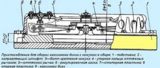
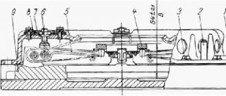
The pressure set should be assembled in the fixture shown in Fig. 235 and under hand press. The device consists of a stand having an installation dimension from the mating plane of the clutch casing to the plane of the pressure plate of 27 ±0.1 mm. In the center of the stand, a mandrel 8 is attached with a bolt 7 to adjust the control size of the pressure set B (see Fig. 33), equal to 64 ± 0.5 mm. The mandrel contains four floating thrust blocks 6 (see Fig. 235).
When installing the pressure set into the fixture, the crackers rest against the legs of the pull levers 4 and, depending on their position, protrude or sink relative to the surface of the mandrel. The length of the mandrel is chosen in such a way that when installed on the pull-out levers of the pressure set with a correctly adjusted control size, the crackers are flush with the surface of the mandrel. The control size of 64±0.5 mm of the clutch pressure set also includes the thickness of the thrust ring of the release levers, which is 6±0.1 mm, and since the pressure set is adjusted in a device without a thrust ring, it must be adjusted to a size reduced by this value, i.e. by 58±0.5 mm.
Assembly and adjustment are carried out in the following sequence:
- The pressure disk is placed on the stand 11 of the device with the working surface down, fixing it with four tenons in the grooves of the stand;
- A needle bearing is inserted into the pull-out levers 4 (20 needles in each hole). The needles are placed on CIATIM-201 lubricant or other grease corresponding to it;
- Forks 6 are installed on the pull-out levers (see Fig. 33);
- insert the fork axles;
- install the assembled levers into the grooves of the pressure disk lugs;
- insert the lever axes;
- put the thrust ring springs on the fork axles;
- secure the axes of the levers and forks with special locking washers, bending the middle of the apron jumper;
- Four loops 10 are put on the ends of the springs of the thrust ring 14;
- Place pressure springs 20 on the bosses of the pressure disk, having previously placed washers with thermal insulating gaskets 21 under them.
When using a pressure disk machined along the working surface by 1 mm, a steel washer 1 mm thick is placed under each pressure spring 20 (from the side of the casing guide cups) to maintain the clutch pressure.
Next, you need to place the clutch housing 19 on the guide pins of the device. All guide cups of the casing must fit into the pressure springs, and the threaded shanks of the forks of the pull-out levers into the holes of the casing. Using a press, it is necessary to press the casing with the mating surface to the device and secure it with bolts, and then release it from under the press. Screw the adjusting nuts 3 onto the threaded shanks of the forks, install a mandrel to adjust the position of the pull-out levers 4 and secure it with a bolt 7 (see Fig. 235). After this, use the adjusting nuts 3 to adjust the position of the pull-out levers 4 so that they all simultaneously touch the thrust blocks 16 of the mandrel. 8, which should be flush with its upper surface. This ensures a control dimension between the working surfaces of the pressure plate and the thrust ring when installing the thrust ring.
Plates 2 are placed on the adjusting nuts 3, then the locking strips and the support plates of the lever forks, after which all eight locking bolts are screwed in. After tightening the bolts, the forks of the pull-out levers should not have any axial play. The bolts are secured by bending the locking strips. Having installed a thrust ring on the pull-out levers, secure it with loops so that it simultaneously touches the supporting surfaces of all four levers.
The runout of the end of the thrust ring relative to the working surface of the pressure plate should not exceed 0.4 mm at a radius of 45 mm. Increased runout of these surfaces can lead to failure of the friction linings of the clutch driven disc and burns to the working surfaces of the flywheel and pressure plate.
How to replace
Replacing the clutch is carried out in several stages:
- dismantling;
- parsing;
- assembly;
- installation.
How to remove
In order to dismantle the coupling mechanism, you must perform the following steps:
- Place the vehicle on a special platform or inspection hole.
- Remove the battery.
- Remove the air filter element.
- Remove the engine splash guards, which are located in the lower and side parts of the power unit compartment.
- Remove the front suspension cross member.
- Remove the front drive wheels.
- Drain the oil fluid.
- Disconnect the speed sensor using a screwdriver.
- Remove the reverse switch.
- Remove the engine harness holder.
- Unscrew the mounting bolts and remove the starter housing.
- Disconnect the engine mounts from the gearbox bracket.
- Move the clutch back.
- Remove the input shaft of the mechanism.
- Unscrew the mounting bolts from the coupling mechanism housing. The bolts are unscrewed one by one, in 2-3 steps.
- Remove the pressure plate along with the casing.
Assembly
Clutch mechanism assembly steps:
- Assemble the driven disk. To do this, it is necessary to attach friction linings to a plastic spring device.
- Assemble the pressure plate. You need to lubricate the rollers with a special liquid, place them in the hole of the pull handles, insert the lever into the groove that is located on the pressure-type disk, and install the finger. Attach the support forks to the levers and secure them with cotter pins.
- Assemble the pressure disk with the casing. This must be done under a press that can compress the springs and screw the bolts into the support forks. A driven type disk is placed under the press, and a pressure disk is placed on top. Heat-insulating washers and the spring mechanisms themselves are installed on special protrusions. Press the casing using a press and tighten the mounting bolts.
- Installing discs into the clutch housing.
Procedure for installing the clutch:
- Install the driven disc so that the extended end of the hub faces the flywheel.
- Install the drive disk element with rods.
- Install a second driven disk with the elongated end of the hub pointing towards the gearbox.
- Install the pressure plate.
- Attach the cut adjusting rings to the structure.
- Install the stop bars and secure them with the casing.
- Install the clutch mechanism on the flywheel, check the gap between the thrust rings and washers by engaging the clutch mechanism.
How to install disks
Many drivers are interested in how the clutch disc is installed on a MAZ.
In order to install clutch discs, you must:
- Disconnect the driveshaft.
- Remove the brake drum and pads from the wheels.
- Using a wrench, unscrew the fasteners from the axle shafts and pull them out.
- Unscrew the screws that adjust the position of the propeller shaft flange and gearbox.
- Disconnect the contacts of the sensor wires, which is responsible for turning on the reverse lights.
- Using a 12mm wrench, unscrew the mounting screws from the clutch mechanism protective cover.
- Remove the casing.
- Using a small crowbar, pry the gearbox housing away from the power unit.
- Remove the basket from the flywheel.
- Secure the flywheel.
- Remove damaged disk elements and replace them with new ones. The driven clutch disc should be directed towards the gearbox, and the pressure disc should be placed so that the hub is directed towards the engine.
- Reassemble the coupling mechanism by performing all steps in reverse order.
Torsional vibration damping and power take-off mechanism
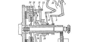
Power units can be equipped with a mechanism for damping torsional vibrations and power take-off (Fig. 3), designed to dampen resonant torsional vibrations and protect transmission systems from destruction.
The mechanism is installed on the engine flywheel and consists of a pressure flange 1, a driven disk 2 with friction linings and a mechanism for damping torsional vibrations, packages of disc springs 5 and stepped bolts 6.
Driven disk 2 is constantly pressed to flywheel 3 through flange 1 by packages of disc springs 5 assembled on stepped bolts 6.
The step bolts are screwed into the flywheel until they stop. When installing stepped bolts, sealant UG-6 TU 6-01-1285-84 is applied to their threaded part, tightening is carried out with a force of 49-59 Nm (5-6 kgcm).
The number of packages of disc springs and bolts is selected so that the friction moment they create allows the transmission of torque from the flywheel to the power take-off shaft up to 1700 Nm (170 kgcm).
When the driven disk is loaded with a torque of more than 1700 Nm (170 kgcm), the force of the springs is not enough to hold the driven disk and it rotates relative to the flywheel and thereby protects further kinematic connection from destruction.
During operation, the mechanism does not require maintenance.
Possible malfunctions of the driven disk during operation are similar to malfunctions of the clutch driven disk.
Premature slipping of the driven disk can be eliminated by installing additional packages of disc springs together with the bolt and further checking the friction torque in the following order:
1. Lock the engine flywheel.
2. Load the driven disk of the mechanism with a torque of less than
1700 Nm (170 kgcm). the disc should not rotate relative to the flywheel.
3. Load the driven disk of the mechanism with a torque of 1700... 1900 Nm (170... 190 kgf). The disk must rotate relative to the flywheel.
Composition of the unit
The double-disc clutch on a MAZ car is a complex mechanism that consists of the following components:
- Main flywheel with crater equipment;
- Release spring;
- Spring pressure;
- Split ring;
- Special rod;
- Stop bar;
- Lever pull mechanism equipped with a fork;
- A thrust ring connected to a pull-out lever;
- Adjusting nut;
- Support plate;
- Clutch release fork mounted with a roller;
- Clutch release device equipped with a bearing. It is attached to the bushing via a flange mounted to the gearbox housing;
- Special casing;
- Simple lever;
- Thermal insulation washer;
- Pressure disc;
- Middle drive type disc;
- Pressure type disc;
- Drive medium type drive;
- Discs: rear and front driven type.
From the last paragraph of this listing, the name of this type of clutch for Masks becomes clear.
Clutch Inspection and Maintenance
First of all, it is worth considering what the clutch drive consists of. The design of this element includes the following parts:
- pedal;
- spring;
- main and working cylinders.
The latter is equipped with a pneumatic amplifier. Additionally, the design provides various pipes and hoses. They are used to transport working fluid. The fluid comes from the main cylinder. Through a special hose it is transferred to a pneumatic amplifier and a compensation tank.
Any actions to configure or pump the MAZ PSU require a complete inspection of the vehicle’s drive system. To do this you will need:
Check the element for tightness. This is done by pressing the pedal about two or three times. Air leaks can be detected by ear. If the leak is weak and no extraneous sounds are heard, then it is checked visually using a soap or other solution. If a breakdown is detected, the failed elements are tightened or completely replaced. Check the condition of the fluid and its level inside the compensator tank. The optimal volume of liquid should be 15-20 mm below the edge of the container neck. If the level is reduced, then it is necessary to top it up to the required volume.
It is important to use liquids of the same brand, otherwise problems may arise during operation. Check the functionality of the release springs, which are attached to the clutch pedal and the fork shaft lever. If a malfunction is detected, it must be eliminated by replacing the elements.
Additionally, during the inspection, you should check how tight the fastening bolts are, which are responsible for fixing the pneumatic amplifier, and also drain the damaged condensate that is inside the amplifier.
Work principles
Pressure-type springs are pushed with one side into the clutch housing, and with the other into the pressure disk, using heat-insulating washers. The pressure plate directs the action to the driven and driven plates, moving them directly to the flywheel. In a situation where the clutch is in the disengaged state, the following happens: cylindrical release springs fill the corresponding gaps that form between all elements of the assembly. Over time, the friction linings of the clutch discs wear out and lose their original appearance, and, accordingly, their characteristics.
MAZ double-disc clutch
How to adjust the double-disc clutch of a MAZ car
Structure and functions of the clutch Malfunctions, causes and actionsAdjusting the clutch and drive
The MAZ double-disc clutch is a transmission element. When it functions correctly, the machine behaves calmly.
However, in the event of a breakdown or other malfunction, malfunctions occur in the MAZ.
In order for the truck to function properly, the clutch must be adjusted regularly. How to do this will be discussed further.
Structure and functions of clutch
The double-disc clutch on a MAZ truck is a complex mechanism. It consists of many parts. If at least one of them is damaged, urgent repairs are required.
In MAZ this transmission mechanism is dry. It is designed according to the friction type. Coil springs occupy space around the periphery. The clutch is assembled in a cast iron crankcase of the MAZ YaMZ 236 generator.
The function of the unit is to briefly separate the shaft of the internal combustion engine from the gearbox. In addition, it plays the role of a uniform connector between the MAZ engine and the gearbox when the truck starts from a standstill, as well as during the subsequent change of gear stages.
Advice! It is necessary to understand the correct calibration of the device. In addition, you should systematically monitor the degree of fixation of the clutch housing with the disc housing. The required degree of tightening is 8-10 kgm.
Operating principles
The essence of the functioning of the transmission element is as follows:
- the pressure springs are pushed with one part into the assembly case, and the second into the pressure plate. All this is done with the help of heat-insulating washers;
- the pressure plate sends the action to the driven plates. In this case, these disks are shifted towards the case.
If the mechanism was at rest, then the cylindrical release springs fill all the required gaps that appear between all the spare parts of the assembly.
During operation of the device, the friction linings of the plates wear out. Their original parameters and properties deteriorate, which means timely replacement is necessary.
Malfunctions, causes and actions
If there are problems with the operation of the MAZ clutch, then you need to know the reasons before taking any action to eliminate them.
Possible breakdowns, causes and solutions are given in the table.
| Malfunction | Cause | Action |
| Slipping | The deactivation clutch play has decreased or is absent | Calibrating the industrial disk, and then adjusting the backlash |
| Worn seals | Replacement of damaged spare parts, after calibration of the device | |
| Linings are oiled or burnt | ||
| No full speed | Assessing the accuracy of pedal calibration and tuning | |
| Pressure plate deformation | Replacing a damaged part | |
| Misalignment of the middle pressure plate | Restoring the space between the plate and screws | |
| Large space between bearing and thrust ring | Setting the shutdown backlash | |
| Weak pedal return or complete failure | Small space between rod nut and rear piston plug | Calibration according to manual |
| Breakage of the rubber-reinforced piston | Part replacement | |
| Weak spring tension | ||
| Jamming of levers due to corrosion/dirt/part geometry violation | Lubricate / clean / level | |
| The valve in the amplifier cylinder is stuck | Remove dirt and lubricate the part |
But these are not the only possible failures of the MAZ double-disc clutch. Malfunctions can occur due to damage to the pneumatic amplifiers and MAZ clutch PGU. Basically, this occurs due to leakage of the working substance or air.
The main solution to the problem is to update the damaged elements.
Clutch Maintenance
Maintenance of the clutch is carried out similarly to the maintenance of the YaMZ-182 clutch (see above) with the addition:
Check each TO-1 and, if necessary, adjust the free play of the clutch release clutch.
The free play of the clutch release clutch, determined by the gap between the thrust ring and the clutch bearing (dimension “A” in Fig. 1. 3.2-4.0 mm), is achieved by adjusting the clutch release mechanism in accordance with the instructions in the vehicle operating instructions.
After adjustments, check the clutch for lack of “driving”. Carry out this check with the engine running with first gear engaged and the clutch disengaged.
Adjusting the free play of the clutch release clutch using the adjusting nuts of the release levers is strictly prohibited.
Clutch replacement
First of all, in order to independently replace the YaMZ 238 clutch with a new one, you need specific skills and at least one assistant. If all this is available, then most likely there will be no serious problems. Let's get started:
- First you will have to remove the gearbox, this is necessary to get to the flywheel and clutch housing.
- Next, unscrew the fastenings of the casing to the flywheel and remove the release disk.
- We unscrew the automatic adjustment bars for the stroke of the middle disk and remove the split rings from the rod.
- Remove the driven, middle, first driven and driving clutch discs.
Done, now you can start installing the new clutch:
- We start by installing the first driven disk. It is placed with the elongated end of the hub towards the flywheel.
- Next, queue 1 and 2 disks.
- Then we install the middle drive disk with rods.
- We install the pressure plate and, using 8 bolts, center the driven disks relative to the crankshaft axis. Having found the desired position, we finally tighten the boots.
- Then you should put on the split rings and install the automatic release adjustment stop bars for the middle pressure plate in place.
- Make sure once again that everything is assembled correctly and that’s it – you can put the gearbox back in place.
In general, the process turns out to be very lengthy and labor-intensive. Depending on the situation, the work may take up to several days. And, most importantly, you should understand that errors in collection are unacceptable. Incorrectly installed parts can lead to destruction of the YaMZ 238 mechanism and damage to the gearbox. Therefore, if you are unsure of yourself, it is better to turn to specialists. Qualified workers will perform the replacement with the necessary guarantees.
Clutch care
In order for the clutch to work as long as possible and not fail unexpectedly, you must follow a few simple rules:
- Periodically check the free play of the pedal, and also lubricate the drive and clutch bearing.
- In order to reduce wear on the clutch elements, you should not keep your foot on the pedal for a long time and use clutch slipping to reduce the speed.
Source
PGU KAMAZ: easy clutch control
» Articles » PGU KAMAZ: easy clutch control To control the clutch in KAMAZ trucks, a pneumohydraulic booster (PGU) is used - this device makes it easier to disengage the clutch and reduces driver fatigue. Read about how the KAMAZ PGU is designed and operates, as well as about its maintenance and some of the nuances of repair in this article.
Purpose and role of PSU in KAMAZ vehicles
In a number of old and all new models of KAMAZ trucks (military 4310, dump trucks 55111, 65115 and 6520, flatbed 43118 and 5320, tractors 5460 and 6460 and others), a pneumohydraulic booster (PGU) is integrated into the clutch drive system. This is due to the need to make the driver’s work easier, since the clutch in a truck has a large mass, and the springs develop a significant clamping force on the discs, and frequent disengagement leads to excessive fatigue.
The PSU greatly simplifies the task of disengaging the clutch, minimizing driver fatigue, while at the same time increasing safety (since in an emergency, disengaging the clutch will not require additional effort, and even at the end of the work shift the driver can easily do it) and improving the controllability of the truck.
It should be noted that in a number of KAMAZ models the PGU is simultaneously included in the control system of the gear divider (multiplier), which is installed between the clutch and the gearbox (most often it is an integral part of the gearbox).
When changing gears, the divider must be turned off, which is ensured by the car's pneumatic system. The divider is switched off using a valve driven by the CCGT rod.
Thus, when using a divider, it is turned off and on automatically simultaneously with the clutch being turned off and on when the pedal is pressed. Such a system is implemented on KAMAZ-5320 and many other models.
General structure and principle of operation of the CCGT unit
Currently, several types of PSUs are used on KAMAZ vehicles, but they all have a fundamentally identical design and operating principle. The amplifier has two interconnected systems combined in a common housing:
- Tracking device;
- Executive pneumatic cylinder.
A tracking device is necessary to control the amplifier; it monitors the force the driver presses the clutch pedal and, at the right moments, supplies air under pressure to the slave cylinder.
The follower device consists of a diaphragm (in some CCGT units it also acts as a gasket between the housing parts) and a piston, which are included in the hydraulic circuit of the clutch pedal, and two associated pneumatic valves (inlet and outlet), which form part of the pneumatic circuit.
Therefore, a tube for supplying brake fluid and a tube for supplying compressed air from the car’s pneumatic system are connected to the amplifier.
The actuator pneumatic cylinder serves directly to drive the clutch. This unit consists of a housing that plays the role of a cylinder, in which a large diameter piston and a spring are installed. The piston is rigidly connected to a pusher, which comes out of the PSU housing through a system of seals - with its help the clutch is disengaged and engaged. In a number of models, a stop is also installed on the pusher, through which the gearbox divider switch-off valve is controlled.
The KAMAZ PGU is a compact unit that is usually mounted directly on the clutch housing. In this case, the amplifier pusher rests against a specially located lever of the clutch release fork shaft. Typically, the pusher does not have a rigid connection with the fork shaft lever, but rests against it through a spherical nut. This solution protects the PSU from damage and also allows adjustments to be made by changing the position of the nut on the pusher.
The KAMAZ PGU operates as follows. When the pedal is depressed, the follower device keeps the inlet pneumatic valve closed, so air from the pneumatic system does not enter the slave cylinder and, under the action of a spring, its piston is retracted to its extreme position - in this case, the clutch is engaged under the action of its springs.
When you press the clutch pedal, the pressure of the working fluid in the follower increases, its piston moves and opens the inlet pneumatic valve - compressed air enters the slave cylinder, overcomes the compression force of the spring and moves the piston - the pusher also moves and disengages the clutch.
When the pedal is released, the opposite processes occur - the inlet pneumatic valve gradually closes and the outlet valve opens, the pressure in the slave cylinder drops, and the clutch is engaged again.
It is important to note that the degree of opening of the follower depends on the force of pressing the clutch pedal, so the driver has the opportunity to regulate the process of engaging and disengaging the clutch depending on the driving mode of the vehicle.
Types of PSU of KAMAZ vehicles
Currently, trucks of the Kama Automobile Plant use several types of CCGT units of domestic and foreign production. They differ in design and applicability.
The CCGT with catalog number 5320 is manufactured at KAMAZ OJSC and has a classic design with a vertical arrangement of the tracking device and the actuating pneumatic cylinder (the tracking device is located above the cylinder body). Used on cars models 5320, 4310, 43118, 55111 and others.
The WABCO PSU is manufactured in the USA, has compact dimensions, and is additionally equipped with a lining wear indicator (allows you to track the life of the amplifier without disassembling it). Used on new models KAMAZ-5460, 6450, 6460, 6520, 6522, 65115, 65116, 65117 and others with gearbox-154 (“Euro-2” and “Euro-3”), as well as on NefAZ buses with the same gearbox .