How does the KamAZ brake system work?
The diagram and design of the brake system of a KamAZ vehicle includes such elements as:
- rear drum brake pad;
- cylindrical brake mechanism of the rear wheels;
- pedal;
- rod with piston part;
- tank for working fluid;
- main cylindrical mechanism and energy accumulators;
- front drum brake pad;
- wheel type cylinder;
- control lamp and pneumatic drive;
- forward pipeline;
- reverse pipeline.
The principle of operation of the brake system of a trailer, semi-trailer:
- When the user presses the brake pedal, an impulse is generated that is transmitted towards the vacuum booster mechanism.
- Through the amplifying element, the impulse is transmitted to the main cylindrical mechanism.
- The piston part of the system moves fuel to the wheel cylindrical parts, which increases the pressure in the brake type drive.
- The piston mechanism begins to move the pads to the disc clutch.
- Movement slows down. Fuel pressure can reach 11-16 MPa. The higher this indicator, the better the braking device works.
- When the user lowers the pedal, it returns to its initial position under the influence of spring parts.
KAMAZ brake release valve
KAMAZ brake release valve
installed on the air distributor and is designed to release the brakes of the trailer (semi-trailer) in the uncoupled state.
Compressed air from the connecting line of a single-wire drive or the supply line of a two-wire drive is supplied to terminal III and then through terminal II enters the trailer air distributor. Terminal I is connected to the trailer cylinder through an air distributor.
When the trailer is coupled to the tractor and air is supplied to port III, valve stem 1 automatically takes the working position.
While the road train is moving, valve rod 1 is in the working position. The inlet valve is open and compressed air flows from port III to port II.
When uncoupling the trailer, the position of the valve does not change; the trailer is braked due to a drop in pressure in the supply line of the two-wire drive or in the connecting line of the single-wire drive.
If you need to move the uncoupled trailer, you need to pull the valve stem 1 all the way towards you. In this case, inlet port III closes (it is connected to the atmosphere), and the cavities of ports I and II are connected, compressed air from the trailer cylinder, supplied to port I, enters the air distributor through port II, and the trailer is released.
Rice. 128. KamAZ brake release valve:
I—output to the air cylinder; II - output to the air distributor; III - output to the connecting or supply line; 1 - rod.
Why are the brakes bad?
Malfunctions of the KamAZ brake system can lead to malfunctions of the vehicle.
Breakdowns and ways to fix them:
- Air in the parking brake system. Because of this, the brake pedal does not release. Air flow can enter the system during depressurization, a drop in fuel level, or due to damaged pipes and hoses. To eliminate the breakdown, it is recommended to bleed the brake mechanism.
- Damaged vacuum. This mechanism directly affects the operation of the brakes. To check its serviceability, you need to press the pedal 5-7 times in a row with the engine turned off. This will help remove the vacuum in the amplifier device. After this, you need to start the unit while holding the pedal. If after starting it drops a little, it means the vacuum is working, if not, then you need to replace the damaged element.
- Extraneous noise while driving may be due to damaged brake pads. In this case, it is recommended to install the KamAZ on a platform and lift it using special equipment, remove the front wheels and inspect the disc elements. The thickness of the disk must be at least 10.8 mm. You also need to check the movement of the pads. Using a screwdriver, they are removed from the disk element; if this cannot be done, then the problem lies in the jamming of the piston mechanism.
Circuit II
This is the rear bogie brake circuit.
The brake structure of the Kamaz 5320 (4310) truck consists of the upper section of the brake valve, part of the triple safety valve, receivers with a total capacity of 40 liters with a pressure sensor and condensate drain valves, an automatic regulator control valve, a two-pointer pressure gauge, four brake chambers, brake mechanisms intermediate and rear axles of the bogie, hose and pipelines.
The circuit includes a pipeline from the brake control valve to the upper section of the brake valve.
Brake system malfunctions and ways to eliminate them
There are four main breakdowns that are associated with a malfunction of the KamAZ brake systems:
- interference with the safety valve;
- clogging in the receiver system or the formation of holes in the hoses;
- hole and loss of compressed air;
- The piston rings are out of order, the sensors are not functioning properly.
In order to timely identify and correct problems with the brakes of KamaAz, regular diagnostics of the operation of its systems, including electronics, are needed. It is recommended to perform it once every two years.
On the Internet you can find a detailed video with an analysis of all the errors. Below we will analyze them briefly, and also consider ways to eliminate them.
Excess oil inside the pneumatic system
The cause of the excess could be wear on the piston rings. It is necessary to urgently replace this part and signal all other work related to them. In models such as KamAZ 5320 and 6520, this problem can lead to serious problems within a short time after it occurs.
There is no air flowing into the receivers
The cause of the breakdown is most often that the pipes through which the air passes are clogged. To fix the problem, simply clean the pipes. On the KamAZ 5511 model, this problem often occurs due to a broken safety valve. In this case, it needs to be replaced.
Receivers in the pneumatic system are not filled quickly enough
There may be several reasons for this failure:
- the connecting elements are not secured well enough;
- the receiver is not secured tightly;
- the hoses through which air passes are damaged;
- The compressor is not operating at full capacity.
Repair methods:
- tighten the connecting parts together more tightly; if necessary, they should be replaced;
- replace the receiver;
- repair or change hoses;
- diagnose the compressor if you need to replace it.
Incorrect pressure in receivers
This malfunction is typical for KamAZ 65115 and 43118. It is necessary to stabilize the regulator; if the breakdown occurs a second time, it should be replaced.
KamAZ does not brake when the brake pedal is pressed
The cause of this problem may be a compressed air leak; it must be found and repaired.
The car brakes poorly or does not brake at all
There may be several reasons:
- circuit 3 hose clogged
- batteries operating on energy spring mechanisms are out of order;
- accelerator valve is broken;
- The brake chamber has failed.
Troubleshooting methods:
- clean the hose using compressed air or replace it;
- replace the brake chamber and energy battery;
- replace all faulty parts;
- inside the brake chamber, repair the stroke of the rods.
The car swerves when braking
There may be two reasons: too much oil has accumulated on the brake pad linings or the brake mechanism requires better adjustment.
The following actions can be a solution to these problems:
- change or clean the linings;
- additionally adjust the brake mechanism.
Spare parts for Ural, Kraz, MAZ, Kamaz trucks. Engine parts YaMZ-236, YaMZ-238
__________________________________________________________________________
__________________________________________________________________________
Brake system of Kamaz vehicles and its drive
__________________________________________________________________
Brake system of Kamaz vehicles
Car brake system KAMAZ-5320, 53212, 53215, KAMAZ-551111, 55102, 5511, KamAZ-5410, 54115, KamAZ-4310, 43114, 43118, KAMAZ-65115, 65111, 53228 consists of four autonomous braking systems: working, spare , parking and auxiliary. Although the brake systems of Kamaz vehicles have common elements, they operate independently and provide high braking efficiency in any operating conditions. In addition, KamAZ-5320, 53212, 53215, KamAZ-55111, 55102, 5511, KamAZ-5410, 54115, KamAZ-4310, 43114, 43118, KamAZ-65115, 65111, 53228, is equipped Investments in movement during automatic braking due to compressed air leakage, alarms and control devices that allow monitoring the operation of the pneumatic drive. The Kamaz braking system is designed to reduce the speed of the vehicle or stop it completely. The service brake system brakes Kamaz-5320, 53212, 53215, Kamaz-55111, 55102, 5511, Kamaz-5410, 54115, Kamaz-4310, 43114, 43118, Kamaz-65115, 65111, 53228 are installed on all six wheels of the vehicle.
The drive of the service brake system is a dual-circuit pneumatic system; it operates separately the brake mechanisms of the front axle and the rear bogie of the vehicle. The drive is controlled by a foot pedal, mechanically connected to the brake valve. The executive bodies of the drive of the working brake system of KamAZ-5320 are the brake chambers. The Kamaz spare brake system is designed to smoothly reduce the speed or stop a moving vehicle in the event of a complete or partial failure of the working system. The Kamaz parking brake system provides braking for a stationary vehicle on a horizontal section, as well as on a slope and in the absence of a driver. The parking brake system is made as a single unit with the spare one, and to activate it, the hand valve handle should be set to the extreme (upper) fixed position. Thus, the rear bogie brakes are common to the service, spare and parking brake systems, and the latter two also have a common pneumatic drive. The brake auxiliary system Kamaz-5320, 53212, 53215, Kamaz-55111, 55102, 5511, Kamaz-5410, 54115, Kamaz-4310, 43114, 43118, Kamaz-65115, 65111, 53228 serves to reduce the load and temperature of the operating brake mechanisms brake systems. The auxiliary braking system on Kamaz vehicles is an engine retarder, when activated, the engine exhaust pipes are blocked and the fuel supply is turned off. The emergency brake release system is designed to release spring energy accumulators when they are automatically activated and the vehicle stops due to a compressed air leak in the drive. The drive of the emergency brake release system is duplicated: in addition to the pneumatic drive, there are emergency release screws in each of the four spring energy accumulators, which allows the latter to be released mechanically. The alarm and control system Kamaz-5320, 53212, 53215, Kamaz-55111, 55102, 5511, Kamaz-5410, 54115, Kamaz-4310, 43114, 43118, Kamaz-65115, 65111, 53228 consists of two parts: - Light and acoustic signaling about the operation of brake systems and their drives. At various points of the pneumatic drive, pneumatic-electric sensors are built in, which, when any braking system, except the auxiliary one, is in operation, closes the circuits of the electric brake light lamps. Pressure drop sensors are installed in the drive receivers and, if there is insufficient pressure in the latter, they close the circuits of the signal lamps located on the vehicle's instrument panel, as well as the sound signal (buzzer) circuit. — Valves of control terminals, with the help of which the technical condition of the Kamaz pneumatic brake drive is diagnosed, as well as (if necessary) the selection of compressed air.
Tractor vehicles are also equipped with a set of pneumatic devices for actuating the brake mechanisms of a trailer (semi-trailer) with a single-wire and two-wire drive. The presence of such a drive on tractors ensures their aggregation with any trailers (semi-trailers) that have a pneumatic drive of the brake mechanisms. The brakes of Kamaz-5320, 53212, 53215, Kamaz-55111, 55102, 5511, Kamaz-5410, 54115, Kamaz-4310, 43114, 43118, Kamaz-65115, 65111, 53228 (Fig. 1) are installed on all six wheels, The main unit of the brake mechanism is mounted on caliper 2, rigidly connected to the bridge flange. Fig.1. Kamaz 1 brake - pad axis; 2 — caliper; 3 — shield; 4 - axle nut; 5 — pad axle lining; 6 — block axis pin; 7 — brake pad; 8 - spring; 9 — friction lining; 10-bracket for expanding fist; 11 — roller axis; 12 — expansion fist; 13 - roller; 14 — adjusting lever Two brake pads 7 with friction linings 9 attached to them, made along a crescent-shaped profile in accordance with the nature of their wear, are freely supported on the eccentrics of the axles 1, fixed in the caliper. The axes of the shoes with eccentric supporting surfaces allow the shoes to be correctly centered relative to the brake drum when assembling the brake mechanisms. The Kamaz brake drum is attached to the wheel hub with five bolts. When braking, the pads Kamaz-5320, 53212, 53215, Kamaz-55111, 55102, 5511, Kamaz-5410, 54115, Kamaz-4310, 43114, 43118, Kamaz-65115, 65111, 53228 are moved apart with an S-shaped fist 12 and when press towards the inner drum surface.
Between the expanding fist 12 and the pads 7, rollers 13 are installed, which reduce friction and improve braking efficiency. The pads are returned to the released state by four release springs 8. The expansion fist 12 rotates in the bracket 10, bolted to the caliper. The brake chamber is installed on this bracket. At the end of the expansion cam shaft there is an adjusting lever 14 of the worm type, connected to the brake chamber rod using a fork and a pin. A shield bolted to the caliper protects the brake mechanism from dirt. The adjusting brake lever (ratchet) Kamaz-5320, 53212, 53215, Kamaz-55111, 55102, 5511, Kamaz-5410, 54115, Kamaz-4310, 43114, 43118, Kamaz-65115, 65111, 53228 is designed to reduce the gap between the pads and brake drum, which increases due to wear of the friction linings. The structure of the adjusting lever (ratchet) is shown in Fig. 2. The adjusting lever has a steel body 6 with a sleeve 7. Fig.2. Adjusting brake lever (ratchet) KamAZ 1 - cover; 2 - rivet; 3 - gear wheel; 4 - plug; 5 - worm; 6 — body; 7 - bushing; 8- locking bolt; 9 — clamp spring; 10 — retainer ball; 11 - worm axis; 12 - oiler In the body of the ratchet Kamaz-5320, 53212, 53215, Kamaz-55111, 55102, 5511, Kamaz-5410, 54115, Kamaz-4310, 43114, 43118, Kamaz-65115, 65111, 53228 there is a worm gear 3rd wheel with splines holes for installation on the expanding fist and the worm 5 with the axis 11 pressed into it. To fix the worm axis there is a locking device, the ball 10 of which fits into the holes on the worm axis 11 under the action of a spring 9 resting against the locking bolt 8. The gear is kept from falling out covers 1 attached to the lever body 6. When the axle is turned (by the square end), the worm turns wheel 3, and the expansion fist turns with it, pushing the pads apart and reducing the gap between the pads and the brake drum. When braking, the adjusting brake lever (ratchet) of the Kamaz vehicle is turned by the brake chamber rod. Before adjusting the gap, lock bolt 8 must be loosened one or two turns; after adjustment, tighten the bolt securely. Adjusting the brakes of KAMAZ cars in the brakes of KAMAZ-5320 cars, 53212, 53215, KamAZ-55111, 55102, 5511, KamAZ-5410, 54115, KAMAZ-4310, 43114, 43118, KAMAZ-65115, 65111, 53228 are performed by two adjustments-partial and partial and part-partial and partial and part-partial and partial complete.
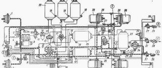
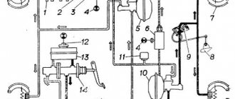
Partial adjustment of the brakes is carried out during operation and is aimed at restoring the normal gap between the shoe linings and the brake drum. The need to adjust the Kamaz brakes is judged by the output of the brake chamber rods, which should be 20 mm when you press the brake pedal. The required stroke value is set using a worm pair of the adjusting lever. When adjusting, the vehicle brake should be cold, the parking brake should be released, the locking bolt 8 should be loosened one or two turns and securely tightened again. To obtain equal braking efficiency for the right and left wheels, the output of the rods of the right and left brake chambers on each axle must be the same. Full adjustment of the brakes of Kamaz-5320, 53212, 53215, Kamaz-55111, 55102, 5511, Kamaz-5410, 54115, Kamaz-4310, 43114, 43118, Kamaz-65115, 65111, 53228 is carried out after disassembling them (replacing the linings or pads ). The purpose of this adjustment is to position the shoes correctly relative to the drum. The brakes are adjusted using the eccentric axes of the pads and the adjusting lever. The brake is considered to be adjusted correctly if the gap between the lining and the brake drum, measured with a feeler gauge through the hatch in the support disk at a distance of 30 mm from the edge of the lining in the upper and lower parts, is within 0.2 ... 0.4 mm, and the feeler gauge is 0.1 mm thick mm does not extend along the entire width of the block. Brake drive for Kamaz vehicles Schematic diagrams of the brake drive for Kamaz-5320, 53212, 53215, Kamaz-55111, 55102, 5511, Kamaz-5410, 54115, Kamaz-4310, 43114, 43118, Kamaz-65115, 65111, 53228 are shown in Fig. 3 . The source of compressed air in the drive is compressor 9. The compressor, pressure regulator 11, fuse 12 against condensate freezing, condensation receiver 20 constitute the supply part of the drive, from which purified compressed air at a given pressure is supplied in the required quantity to the remaining parts of the pneumatic brake drive and to other consumers of compressed air. The pneumatic brake drive Kamaz-5320, 53212, 53215, Kamaz-55111, 55102, 5511, Kamaz-5410, 54115, Kamaz-4310, 43114, 43118, Kamaz-65115, 65111, 53228 is divided into autonomous circuits, separated from each other by protection nym valves. Each circuit operates independently of other circuits, including when faults occur. The pneumatic brake actuator consists of five circuits separated by one double and one triple safety valve.
Rice. 3. Diagram of the pneumatic drive of the brake mechanisms of the Kamaz 5320 A vehicle - control output of circuit IV; B, E - valves of control terminals of the third circuit; C - control output of circuit I; D - control output of circuit II; N — brake control line of a two-wire drive; P — connecting line of a single-wire drive; K - line supplying a two-wire drive; 1 — brake chambers type 24; 2 — parking brake system control valve; 3 — emergency brake release valve for the parking brake system; 4 — auxiliary brake system control valve; 5 — two-pointer pressure gauge; 6 — control lamps and sound signaling device; 7 — control valve; 8 — pressure limitation valve; 9 - compressor; 10 — pneumatic cylinder for driving the engine stop lever; 11 — pressure regulator; 12 - anti-freeze fuse; 13 — double safety valve; 14 — sensor for turning on the solenoid valve of the trailer brake mechanism; 15 — rechargeable batteries; 16 — two-section brake valve; 17 — triple safety valve; 18 — pressure drop sensor in the receiver; 19 — condensate drain valves; 20 — condensing receiver; 21 — air bleed valve; 22 — receivers of circuit II; 23 — pneumatic cylinder for the auxiliary brake system flap drive; 24, 25 — receivers of circuits I and III; 26 — brake chambers of type 20×20; 27 — sensor for turning on the warning lamp of the parking brake system; 28 — energy accumulators; 29 — accelerator valve; 30 — automatic brake force regulator; 31 — trailer brake control valve with a two-wire drive; 32 — two-line valve; 33 — sensor for turning on the brake signal; 34 — trailer brake control valve with a single-wire drive; 35 — single safety valve; 36 — rear lights; 37 — isolation valves; 38, 39 — connection heads type A and type “Palm”
Fig.4. Diagram of the pneumatic drive of the brakes of Kamaz-65115 vehicles 1 - water separator; 2 - compressor; 3 - cooler; 4 - four-circuit safety valve; 5 - automatic brake force regulator; 6 — pressure regulator; 7 - brake signal switch; 8 - brake valve; 9 — pneumatic cylinders for the flap drive of the auxiliary brake system mechanism; 10 — parking brake system control valve; 11 - proportional valve; 12 - pneumatic cylinder for driving the engine stop lever; 13 — auxiliary brake system control valve; 14 - pressure gauge; 15- brake chambers type 30/30; 16 - receiver circuit 1Y; 17 — receivers of circuit 11; 18 — condensate drain valve; 19 — brake chambers type 20/20; 20.24 - accelerator valves; 21 - two-line bypass valve; 26 switch for the parking brake system warning lamp; 23 — receiver of circuit III; 25 — receiver of circuit I; 26 — switch for warning lamp for air pressure drop in circuit III; 27 — emergency release valve Circuit I of the front axle service brake drive KamAZ-5320, 53212, 53215, KamAZ-55111, 55102, 5511, KamAZ-5410, 54115, KamAZ-4310, 43114, 43118, Kamaz-65115, 65111, 5 3228 consists from part of the triple safety valve 17; receiver 24 with a capacity of 20 liters with a condensate drain valve and pressure drop sensor 18 in the receiver, part of a two-pointer pressure gauge 5; lower section of a two-section brake valve 16; valve 7 control terminal (C); pressure limit valve 8; two brake chambers 1; brake mechanisms of the front axle of the tractor; pipelines and hoses between these devices. In addition, the drive circuit for the front axle service brakes includes a pipeline from the lower section of the brake valve 16 to the valve 31 for controlling the brake systems of a trailer with a two-wire drive. Circuit II of the service brake drive of the rear bogie Kamaz-5320, 53212, 53215, Kamaz-55111, 55102, 5511, Kamaz-5410, 54115, Kamaz-4310, 43114, 43118, Kamaz-65115, 65111, 53228 consists of a part of a triple safety valve 17; 22 receivers with a total capacity of 40 liters with condensate drain valves 19 and pressure drop sensor 18 in the receiver; parts of a two-pointer pressure gauge 5; the upper section of the two-section brake valve 16; control output valve (D) of the automatic brake force regulator 30 with an elastic element; four brake chambers 26; brake mechanisms of the rear bogie (intermediate and rear axles); pipelines and hoses between these devices. The drive circuit for the service brakes of the rear bogie also includes a pipeline from the upper section of the brake valve 16 to the brake control valve 31 with a two-wire drive. Circuit III of the drive mechanisms of the spare and parking brake systems of Kamaz, as well as the combined drive of the trailer (semi-trailer) brakes, consists of a part of the double safety valve 13; two receivers 25 with a total capacity of 40 liters with a condensate drain valve 19 and a pressure drop sensor 18 in the receivers; two valves 7 control output (B and E) of manual brake valve 2; accelerator valve 29; parts of a two-line bypass valve 32; four spring energy accumulators 28 brake chambers; sensor 27 for pressure drop in the line of spring energy accumulators; valve 31 for controlling the brake mechanisms of a trailer with a two-wire drive; single safety valve 35; valve 34 for controlling the brake mechanisms of a trailer with a single-wire drive; three isolation valves 37 three connection heads; heads 38 type A for a single-wire drive of trailer brakes and two heads 39 of type “Palm” for a two-wire drive of trailer brakes; pneumoelectric sensor 33 of the “stop light”, pipelines and hoses between these devices. It should be noted that the pneumoelectric sensor 33 in the circuit is installed in such a way that it ensures that the brake light lamps turn on when the vehicle is braking not only by the spare (parking) brake system, but also by the working one, and also in the event of failure of one of the circuits of the latter . Circuit IV of the drive of the auxiliary brake system of Kamaz-5320, 53212, 53215, Kamaz-55111, 55102, 5511, Kamaz-5410, 54115, Kamaz-4310, 43114, 43118, Kamaz-65115, 65111, 53228 and other consumers does not have its own receiver and consists of a part of a double safety valve 13; pneumatic valve 4; two cylinders 23 damper drives; cylinder 10 of the engine stop lever drive; pneumoelectric sensor 14; pipelines and hoses between these devices. From circuit IV of the drive mechanisms of the auxiliary brake system, compressed air is supplied to additional (non-brake) consumers; pneumatic signal, pneumohydraulic clutch booster, control of transmission units, etc. Circuit V of the emergency brake release drive Kamaz-5320, 53212, 53215, Kamaz-55111, 55102, 5511, Kamaz-5410, 54115, Kamaz-4310, 43114, 43118, Kamaz-6 5115 , 65111, 53228 does not have its own receiver and executive bodies. It consists of a triple safety valve part 17; pneumatic valve 4; parts of a two-line bypass valve 32; pipelines and hoses connecting the devices. The pneumatic brake actuators of the tractor and trailer connect three lines: the single-wire drive line, the supply and control (brake) lines of the two-wire drive. On truck tractors, connecting heads 38 and 39 are located at the ends of three flexible hoses of the said lines, mounted on a support rod. On flatbed vehicles, heads 38 and 39 are mounted on the rear cross member of the frame. To improve moisture separation in the supply part of the brake drive KamAZ 53212, 53213 in the compressor-pressure regulator section, a moisture separator is additionally provided, installed on the first cross member of the vehicle in the intensive airflow zone. For the same purpose, on all car models, a condensation receiver with a capacity of 20 liters is provided in the section against freezing - protective valves. The Kamaz 55111 dump truck does not have trailer brake control equipment, disconnect valves, or connecting heads. To monitor the operation of the pneumatic brake drive Kamaz-5320, 53212, 53215, Kamaz-55111, 55102, 5511, Kamaz-5410, 54115, Kamaz-4310, 43114, 43118, Kamaz-65115, 65111, 53228 and timely alarm about its condition and any malfunctions that arise in the cockpit, there are five signal lights on the instrument panel, a two-pointer pressure gauge indicating the compressed air pressure in the receivers of two circuits (I and II) of the pneumatic drive of the service brake system, and a buzzer signaling an emergency drop in compressed air pressure in the receivers of any brake circuit drive. Mechanism of the auxiliary brake system of Kamaz vehicles Fig.5. Mechanism of the auxiliary brake system Kamaz 1 - housing; 2 — rotary lever; 3 - damper; 4 - shaft In the exhaust pipes of the muffler there is a housing 1 and a damper 3 mounted on shaft 4. A rotary lever 2 connected to the pneumatic cylinder rod is also attached to the damper shaft. Lever 2 and the associated damper 3 have two positions. The internal cavity of the body is spherical. When the auxiliary brake system is turned off, damper 3 is installed along the flow of exhaust gases, and when turned on, it is perpendicular to the flow, creating a certain back pressure in the exhaust manifolds. At the same time, the fuel supply is stopped. The engine starts operating in compressor mode.
_________________________________________________________________________
_________________________________________________________________________
_________________________________________________________________________
- Cardan shafts and power take-off Ural-4320
- Transmission gearbox Ural-4320
- Bridges Ural-4320
- Transfer case Ural-4320
- Steering Ural-4320
- Truck cranes and cranes based on trucks
_________________________________________________________________________
_________________________________________________________________________
- Cylinder block and cylinder head YaMZ-236 HE2, YaMZ-236 BE2
- Checking and adjusting YaMZ-236
- Power system and lubrication system YaMZ-236
- Driven and driven clutch discs YaMZ-236, 238
- Cooling and lubrication systems YaMZ-238
- Fuel injection pump YaMZ-238
_________________________________________________________________________
- Kamaz diesel engine
- Repair and adjustment of Kamaz power steering
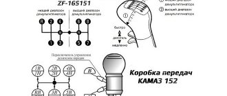
- Kamaz-152 gearbox with divider
- Gearbox parts for Kamaz-5320 gearbox
- Kamaz transfer case and driveshafts
- Kamaz gearbox repair
- Clutch KamAZ-5320
- Construction of Kamaz-4310 drive axles
- Power steering MAZ-5551, 5549, 5335, 5336, 5337
- Front axle and steering rods MAZ-5551, 5549, 5335, 5336, 5337
- Clutch adjustment MAZ-5551, 5549, 5335, 5336, 5337
- Adjustment and repair of gearboxes MAZ-5551, 5549, 5335, 5336, 5337
- Repair and maintenance of the rear axle MAZ-5551, 5549, 5335, 5336, 5337
- Front axle parts and steering rods MAZ-5516, 5440
- Steering Maz-5516, 5440
- Details of driving axles Maz-5516, 5440
- Clutch device ZIL-130
- Repair of ZIL-130 gearbox
- Repair of rear axle ZIL-130
- Basic parts of the ZIL-130 engine
- Transfer case and power take-off ZIL-131
- Drive axles ZIL-131
- Steering ZIL-131
- Maintenance of ZIL-645 engine parts
How to improve your brakes
Repairing the KamAZ brake system and tuning will help improve the performance of this mechanism:
- Replacing standard discs with larger diameter ones. To install them, you need to drill special holes that must coincide with the mounting bolts of the tuning part. In some cases, plates may be required to support calipers over larger disc mechanisms. You should also purchase wheels that are larger in size and width.
- Replacing the standard mechanism with a ventilated disc or device with notches of the same size. Calipers must be installed on each disc using reliable fasteners. This method will help increase the efficiency of the brake chamber by 2 times.
When carrying out work to improve brake performance, the following recommendations must be observed:
- The brake design itself is prohibited from changing at the legislative level. Any changes will be detected during regular technical inspection.
- All parts should be selected only from reliable manufacturers who have passed the certification procedure.
- Tuning can only be done if all elements of the system are in good condition.
There are many videos on the Internet on how to improve the brakes on KamAZ. Typically, model 5511 is used as an example. Improving the brakes is best left to professionals, since if you adjust it yourself, there is a chance of completely ruining the system.
If the brake in a car does not work well, then you should first check whether all the auxiliary systems are working properly, and only then understand the brake mechanism.
KamAZ is a fairly large vehicle, which means its brakes must work at 100%. We advise you not to try to improve the car yourself.
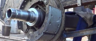
How to remove a brake drum
Before performing this procedure, you should wear protection, such as a mask or goggles.
To remove the brake drum, do the following:
- Place the vehicle on a special platform.
- Stop the engine and raise the handbrake.
- Loosen the bolt tension.
- Using a wheel wrench, turn each nut 1 turn counterclockwise.
- Raise KamAZ using a special device.
- Unscrew the bolts and remove the wheel.
- Using a wheel wrench, remove any loose wheel nuts.
- Remove the cap and put all unscrewed fasteners into it.
- Remove the wheel from the guides.
- Loosen the pads by unscrewing the adjuster screw, which is located on the outside of the drum part.
- Turn the drum so that the hole aligns with the adjuster screw.
- Turn the regulator screw clockwise until it stops.
- Remove the drum.
- Using a screwdriver, remove the screws that hold this mechanism to the wheel.
- Pull the drum towards you using a special puller.
- Insert a screwdriver under the flange of the drum mechanism.
- Lightly tap the lever, screwdriver, or the drum itself.
How to adjust
To adjust the brakes on KamAZ you need:
- Check the movement of the brake lever. It should move freely and return to its original position.
- Align the holes in the handle body and the mechanism rod fork by rotating the worm.
- Press the control unit all the way in the direction of its rotation.
- Using bolts and nuts, connect the fixing type bracket to the control unit of the handle. The position of the block should remain the same.
- Rotating the worm, open the brakes until the pads touch the drum mechanism.
- Turn the worm in the opposite direction ¾ of a turn. The gear coupling must work, and the turning torque of the worm must be at least 42 Nm.
- Check the functionality of the handle. To do this, you need to release the brakes of the vehicle in place by pressing the pedal all the way.
- Check the serviceability of the rod. It should move without binding.
- Adjust the stroke of the rod according to the required clearance by rotating the worm.
- Check the uniform rotation of the drum mechanism.
After 2-6 km, inspect the mechanism for heating of the drum device. The temperature should not exceed +60…+80°C.
Possible breakdowns
If the system has some damage, it may bleed air slowly or even quickly. This causes the brakes to start to fail. If you set the parking brake on a problematic car, it will release the brakes, which can lead to serious trouble.
If the handbrake on a KamAZ truck does not work, the reasons may be different:
- wear of seals - for example, o-rings and seals. In this case, the system releases air slowly, which can sometimes be accompanied by a slight whistle;
- damage to the line circuits is a very serious problem, which can result in the rapid release of air from the system and automatic braking of the car even while driving;
- freezing – in the cold season, the handbrake tends to freeze. If KamAZ is not removed from the handbrake, the reason may lie precisely in the fact that the temperature inside the line has dropped below zero. The essence of the problem is that moisture forms in the system, which should not be there.
There can be much more probable breakdowns - for example, the handbrake on a KamAZ truck does not hold, which indicates wear and tear on the mechanical parts of the system. But only those faults that occur most often are considered here. You can also read about How to knock out a kingpin on a KamAZ.
Kamaz 6520 engine parameters
All parameters of the Kamaz 6520 engine:
- EURO-5 standard;
- engine type: eight-cylinder, diesel, V-shaped arrangement;
- engine model 740.735-400;
- power (horsepower) 400;
- equipment fuel injection pump model BOSCH;
- fuel tank capacity 350 l;
- Common Rail fuel system type;
- engine weight 885 kg.
Engine KamAZ-6520
Purpose of KamAZ 6520
Kamaz 6520: technical characteristics, reviews, tests, photos and prices - this review will tell you about it. But before moving on to the parameters and characteristics, let's find out what purpose this car has and in what area it is used.
All KAMAZ trucks are designed to perform complex cargo work; they transport bulk construction materials, and can also serve as grain carriers, concrete mixer trucks, timber trucks and simply serve as a dump truck. This model belongs specifically to dump trucks, has a large body capacity, the vehicle is quite suitable for transporting large loads, logs, bricks, small concrete slabs.
Scope of application of KamAZ 6520: construction, transportation, road construction, quarrying.
The manufacturer's model range includes many modifications of Kamaz vehicles, each of which is functional and suitable for heavy tasks. Kamaz vehicles are produced of the following types: chassis, dump trucks, cranes, concrete mixers. In fact, all these vehicles are “relatives” to each other.
What modifications/configurations are there?
Modifications of KAMAZ 6520:
- 6520 - 6012-53 (platform volume 20 cubic meters);
- 6520 - 6013-53 (platform volume, cubic meters 16);
- 6520 - 6014-53 (platform volume, cubic m 12).
All three modifications have the same technical parameters, engine type, load capacity, cabin design, fuel tank volume and fuel equipment design, as well as the loading platform. The only difference between them is the volume of the cargo platform (the volume is indicated above, in brackets opposite each model).
Kamaz 6520 - 6013-53
Driver's workplace: what does it look like?
The cabin in KamAZ 6520 is standard, restyled, without a berth. But the arrangement of the cabins is good. The driver and passenger seats are comfortable, the cabin is equipped with soft seats and high-quality sound insulation, which is especially important when driving on the highway. The streamlining of the cabin is increased, and due to the special external shape of the edges of the cabin, much less dirt gets onto this part of the car. In winter, the cabin retains heat well. Steering is carried out
Vehicle specifications
The technical parameters of KamAZ 6520 are as follows:
- wheel formula - 6x4;
- car weight in kg. — 33100 (33t);
- maximum load capacity - 20075 kg;
- load on the front axle of the dump truck - 7500 kg;
- load on the rear bogie - 26500 kg;
- dimensions of KamAZ 65115: length 7730 mm, width 2550 mm, height 3120 mm;
- tire size - 315/80 R22.5;
- the body is of the tipper platform type;
- platform volume is 20/16/12 cubic meters. m, depending on modification;
- center distance 3600+1440;
- front/rear overhang - 1350/1440;
- the maximum speed of the KamAZ 6520 is 100 kilometers per hour;
- fuel consumption per 100 km. (30-40 liters);
- rear unloading type (all modifications).