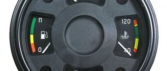
KAMAZ gearbox provides indication:
- vehicle speed;
- engine rotation speed;
- fuel level;
- coolant temperature;
- air pressure in circuit 1;
- air pressure in circuit 2;
b) using the parameter monitor:
- total mileage;
- daily mileage;
- urea level;
- engine oil pressure;
- coolant temperature;
- transmission oil temperature;
- on-board network voltage;
- engine operating hours;
- fuel consumption per 100 km;
- fuel consumption per 1 hour;
- number of pulses;
- vehicle speed;
- engine oil level;
c) using light and sound alarms:
- condition of vehicle systems and components.
It is possible to enter the values of the gear ratio of the generator drive to the crankshaft and the number of pairs of poles of the generator field winding, the values of the boundaries of the engine monitoring zones, the values of the lower limit of the zone for exceeding the maximum permissible speed.
The CAN interface is used as an external interface for data exchange between the KAMAZ gearbox and other vehicle devices.
KAMAZ gearbox is manufactured in climatic versions U2 for operation in the temperature range from minus 40 °C to plus 60 °C (69.3801, 69.3801-01) and T2 for operation in the temperature range from minus 20 °C to plus 60 °C (6907.3801, 6907.3801 -01).
Specifications:
| Range of vehicle speed readings, km/h | 0—125 | |
| Engine crankshaft speed reading range, 1/min | 0—3100 | |
| Fuel level reading range | 0—1 | |
| Range of coolant temperature readings, °C | 40—120 | |
| Range of air pressure readings in circuit 1, kgf/cm^2 | 0—10 | |
| Range of air pressure readings in circuit 2, kgf/cm^2 | 0—10 | |
| Range of total mileage readings, km | 0—999999,9 | |
| Range of daily mileage readings, km | 0—9999,9 | |
| Range of urea level readings, % | 0—100 | |
| Engine oil pressure reading range, kgf/cm^2 | 0—10,5 | |
| Range of transmission oil temperature readings, °C | minus 50—250 | |
| On-board network voltage reading range, V | 14—33 | |
| Range of engine operating hours, engine hours | 0—99999,9 | |
| Range of fuel consumption readings per 100 km, l/100 km | 0—999,9 | |
| Range of fuel consumption readings for 1 hour, l/h | 0—999,9 | |
| Range of indications of the number of pulses, pulses | 0—65536 | |
| Engine oil level reading range, % | 0—100 | |
| Rated voltage, V | 24 | |
| Maximum current consumption, no more, A | 1.5 (with the ignition switch on, on-board voltage - 27 V); 0.025 (with the ignition switch off, on-board voltage - 24 V) | |
| Overall dimensions, no more, mm | 470x180x90 | |
| Weight, no more, kg | 1,5 | |
The product “Instrument cluster KAMAZ 69.3801-01” has been supplied since May 2015, replaces the version “Instrument cluster KAMAZ 69.3801” and additionally allows: • connecting analog pressure sensors with a potential output (with output voltage from 1 to 5 V) to indicate the “Pressure” parameters air in circuit 1", "Air pressure in circuit 2", "Engine oil pressure"; • connect two discrete brake lining wear sensors; • display the following parameters on the monitor: “Vehicle speed”, “Engine oil level”.
Instructions for use:
Instrument cluster KAMAZ 69.3801 (manufactured from August 2012 to April 2014) Operating manual ADIG.453895.009 RE
Instrument cluster KAMAZ 69.3801 (manufactured from May 2014 to April 2015) Operating manual ADIG.453895.009-02 RE
Instrument cluster KAMAZ 69.3801-01 (manufactured from May 2015 to October 2016) Operating manual ADIG.453895.009-06 RE
Instrument cluster KAMAZ 69.3801-01 (manufactured from November 2016 to July 2017) Operating manual ADIG.453895.009-06 RE
Instrument cluster KAMAZ 69.3801-01 (manufactured from August 2017 to October 2019) Operating manual ADIG.453895.009-06 RE
Instrument cluster KamAZ 69.3801. Pinout.
Instrument cluster KamAZ 69.3801. Pinout.
Rear panel of the KamAZ 69.3801 instrument cluster.
1 — password label; 2 - place for marking the serial number of the product; 3 — place of marking of the mark of conformity of the certification system (if there is a certificate); 4 — logo of the product manufacturer’s trademark; 5 — sticker; 6 — place of marking of the product designation; 7 — place of marking of technical specifications; 8 - place for marking the date of manufacture; 9 — connector “EZ”; 10 — sealing label; 11 — connector “E2”; 12 — connector “D”; 13 — connector “C”; 14 — connector “B”; 15 — connector “A”.
Connector “EZ” 953236-1.
| Contact | Contact assignment |
| 1 | Signal input for the “Transport position” indicator — “0 V” (signal — orange) |
| 2 | Signal input for the “Vehicle platform height adjustment” indicator is “0 V” (signal is red) |
| 3 | Free contact |
| 4 | Free contact |
| 5 | Free contact |
| 6 | Free contact |
| 7 | Signal input for the “ABS tractor” indicator is “0 V” (signal - orange) |
| 8 | Signal input for the "Trailer ABS" indicator - "0 V" (signal - orange) |
| 9 | Signal input for the "Engine fault" indicator - "0 V" (signal - orange) |
| 10 | Signal input 1 for the “Engine emergency” indicator - “0 V” (signal - red) |
| 11 | Signal input 2 for the “Engine emergency” indicator - “0 V” (signal - red) |
| 12 | Signal input for the "EFU" indicator - "0 V" (signal - orange) |
| 13 | Signal input for the indicator “Error in the exhaust gas aftertreatment system” - “0 V” (signal - red) |
| 14 | Free contact |
| 15 | Free contact |
| 16 | Free contact |
| 17 | Free contact |
| 18 | Free contact |
| 19 | Free contact |
| 20 | Free contact |
| 21 | Free contact |
| 22 | Free contact |
| 23 | Signal input for the “Traction control” indicator is “0 V” (signal - orange) |
| 24 | Free contact |
| 25 | Free contact |
| 26 | Free contact |
Connector “E2” 953118-4.
Design of the central unit of the instrument cluster 56.3801-01
External view of the front panel of the central unit of the instrument cluster 56.3801-01
(CBCP) is shown in Figure 1.1, and the functional purpose of the front panel elements is shown in Figure 1.2.
The appearance of the rear panel is shown in Figure 1.3, and the functional purpose of the connector contacts is given in Table 1.14.
All four connectors have a different number of contacts, which eliminates incorrect connection of the harnesses to the CBCP.
A sealing label with the inscription “ELARA” is located between connectors XP1 and XP2.
Figure 1.1 - CBCP. Appearance of the front panel 1 - liquid crystal indicator (LCD); 2 — pointer indicator of the fuel level indicating device; 3 - pointer indicator indicating air pressure in the first working circuit; 4 — left “Control” button; 5 - ; 6 — right button “Set minutes”; 7 - pointer indicator indicating air pressure in the second working circuit; 8 — arrow pointer indicating the coolant temperature.
| Signposts : | |
| fuel level (in the indicator area there is a reserve fuel remaining indicator - O) | |
| air pressure in the first working circuit | |
| coolant temperature (in the indicator area there is an emergency cooling temperature indicator - O) | |
| air pressure in the second operating circuit | |
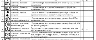
| Alarms : | |
| cabin lock | |
| parking brake | |
| winch | |
| parking lights | |
| demultiplier | |
| emergency oil pressure | |
| transfer case differential lock | |
| fan drive clutch | |
| turning the tractor | |
| trailer rotation | |
| EFU | |
| Tractor ABS | |
| emergency air pressure in the primary circuit | |
| emergency air pressure in circuit III | |
| emergency oil temperature | |
| high beam | |
| rear fog lights | |
| neutral gearbox | |
| Trailer ABS | |
| emergency air pressure in circuit II | |
| emergency air pressure in the IV circuit | |
| battery discharge | |
| center differential lock, BMOD (BMOD 1 - located at the top, BMOD 2 - located at the bottom) | |
| interwheel differential lock, BMKD (BMKD 1 - located at the top; BMKD 2 - located at the bottom) | |
| STOP | |
| air filter clogged | |
| power take-off box, PTO (PTO 1 is located at the top, PTO 2 is located at the bottom | |
| LCD | |
| 40°C | indication of external air temperature (2nd line) |
| 24.0 V | On-board voltage indication (1st line) |
| kgf cm22.0 | oil pressure indication (2nd line) |
| 15:35:00 | indication of the current time of day (2nd line) |
| P-On | indication of the status of the audible parking brake alarm (2nd line) |
| Buttons | |
| left button: "Manage" | |
| right button: “Set minutes” | |
Figure 1.2 - CBCP. Front panel elements.
Figure 1.3 — TsBKP Appearance of the rear panel 1 — “ХР1” connector; 2 — connector “ХРЗ”; 3 — connector “ХР4”; 4 - location for marking the date of manufacture; 5 - place of marking of technical specifications; 6 - place for marking the serial number of the product; 7 — place of marking of the mark of conformity of the certification system (if there is a certificate); 8 — the value of the rated supply voltage of the product; 9 — place of marking of the product designation; 10 — connector “ХР2”; 11 - sealing label; 12 — logo of the product manufacturer’s trademark.
Table 1.14
| Connector | Contact | Signal name |
| XP1 | 1 | Sound alarm |
| 2 | Air filter clogged | |
| 3 | High beam | |
| 4 | Rear fog lights | |
| 5 | Neutral gearbox | |
| 6 | Trailer ABS pin 1 | |
| 7 | Trailer ABS pin 2 | |
| 8 | ||
| 9 | ||
| XP2 | 1 | |
| 2 | Cabin lock | |
| 3 | Parking brake | |
| 4 | Trailer rotation | |
| 5 | Turning the tractor | |
| 6 | EFU | |
| 7 | ||
| 8 | Tractor ABS contact 1 | |
| 9 | Tractor ABS contact 2 | |
| 10 | Emergency fuel remaining | |
| 11 | Backlight | |
| XP3 | 1 | Instrument and starter switch lock |
| 2 | Weight | |
| 3 | Emergency coolant temperature | |
| 4 | Power take-off 1 | |
| 5 | K-Line | |
| 6 | Fan drive clutch contact 1 | |
| 7 | Fan drive clutch contact 2 | |
| 8 | Cross-axle differential lock 1 | |
| 9 | Cross-axle differential lock 2 | |
| 10 | Center differential lock 1 | |
| 11 | Center differential lock 2 | |
| 12 | ||
| 13 | Emergency air pressure of the 2nd circuit | |
| 14 | Emergency air pressure of the IV circuit | |
| 15 | Emergency air pressure of the first circuit | |
| 16 | Power take-off 2 | |
| 17 | Battery discharge | |
| 18 | Emergency oil temperature | |
| 19 | Emergency air pressure of the third circuit | |
| XP4 | 1 | |
| 2 | Fuel level sensor | |
| 3 | Coolant temperature sensor | |
| 4 | Air pressure sensor in the 1st brake operating circuit | |
| 5 | External temperature sensor | |
| 6 | Air pressure sensor in the 2nd brake operating circuit | |
| 7 | Oil pressure sensor | |
| 8 | parking lights | |
| 9 | Transfer case differential lock pin 1 | |
| 10 | Demultiplier | |
| 11 | Winch | |
| 12 | Transfer case differential lock pin 2 | |
| 13 | Emergency oil pressure | |
| 14 | Weight | |
| 15 | Battery "+" |
KamAZ 43118 - technical characteristics
KamAZ-43118 is an all-wheel drive truck with a 6 × 6 wheel arrangement. This vehicle, with its high cross-country ability, has become simply irreplaceable in hard-to-reach areas of Russia. Also, having a lifting capacity of 10 tons, the machine became the basis for a large number of various special equipment and, above all, truck cranes.
KamAZ-43118 has the following overall dimensions (in millimeters):
- Length – 8580;
- Width – 2500;
- Height – 3455;
- Ground clearance – 385;
- Wheelbase – 3960+1320.
The vehicle is equipped with a KamAZ-740.30-260 diesel engine that meets Euro-2 environmental standards. This power unit is made according to the V8 formula. It has a displacement of 10.85 liters, is equipped with a turbocharger and develops a power of 260 hp. With.
This power unit allows the car to reach a maximum speed of 90 km/h.
The empty weight of the truck is 10,400 kg. The weight of a fully loaded vehicle can be 20,700 kg.
Kamaz windshield wiper motor connection diagram
The windshield cleaning system is designed to wash and clean windshields to ensure vehicle safety.
It includes electric windshield wipers 27.5205 and windshield washers 1112.5208-01.
The electric windshield washer is controlled by a key switch and has an electric pump built into the washer reservoir.
The pump is powered through a 10A fuse.
The electric windshield wiper ensures that the blades operate in two modes and stop in their original position. It includes a gear motor, motorized brushes and a three-position switch.
Voltage is supplied to the gearmotor through the heater motor relay, so the windshield wiper can be turned on when the instrument and starter switch is turned to position “1”.
The washer and wiper switches are located to the right of the steering column on the switch panel.
When the washer switch is turned on, current flows through the pump motor.
“+“ batteries, starter terminal, terminal B of the starter relay —► ammeter, terminal 1G connector, terminals 1G and 57 of the fuse block for current 60 and 30 A —► fuse for current 10 A —► open switch contacts —► electric motor washer —► housing —► “mass” switch — “—“ battery. The electric motor drives a pump, which supplies washer fluid through flexible tubes to two single-jet nozzles and then to the windshield.
The electric motor of the windshield wiper gearmotor has three brushes: one negative and two positive.
The negative blade is connected to the car body, and the positive blades are supplied with on-board voltage through the wiper switch.
When voltage is applied to different positive brushes, different speeds of the electric motor armature and, accordingly, different operating modes of the windshield wiper blades are provided.
The design and replacement of the windshield wiper is described in the article: Design and replacement of the windshield wiper of a KAMAZ vehicle
The operating order of the windshield wiper is as follows:
— when the instrument switch and starter are set to position “1”, the heater electric motor relay is activated, since a voltage of 7.5 A is supplied to its winding from the short-circuit terminal of the instrument switch and starter through a fuse for a current of 7.5 A;
— when the relay is triggered, the voltage from its pin 30 is supplied to pin 87 and then through a 10 A current fuse to pin 110 of the gearmotor connector, gearmotor fuse, pin 110A of the gearmotor, pin 110A of the switch;
— in position “1” of the windshield wiper switch, the voltage from its terminal 110A is supplied to terminal 111 and then to one of the positive brushes of the gearmotor (top in the figure). At the same time, current begins to flow through the electric motor, since its negative brush (lower in the figure) is constantly connected to the car body; the electric motor, through a gearbox and drive, ensures reciprocating movement of the brushes with a certain frequency;
— when the windshield wiper switch is set to position “2”, the voltage from its terminal 110A is supplied to terminal 112 and then to the second positive blade (in the figure on the left); with this switch position, the windshield wiper operates more frequently;
— when the windshield wiper is turned off, the brushes are returned to their original position using the limit switch S1 of the gearmotor. The state of the switch contacts (see Fig. 2) is shown for the initial state.
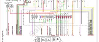
Power supply system for KamAZ-43118 vehicle
This system, perhaps, can be considered the main one in the car; thanks to this system, the truck is supplied with electricity when the power unit is running. The general diagram of the power supply system is presented below:
In the figure the numbers indicate:
- generator excitation winding cut-off relay;
- generator;
- fuse box;
- starter relay;
- starter;
- rechargeable batteries;
- mains switch;
- button for remote battery disconnect switch;
- heater motor relay;
- ammeter;
- fuses 13.3722 (7.5 A);
- fuse PR310 (10 A);
- instrument and starter switch;
I. to the EFU thermal relay
Brief explanations of the diagram:
The energy sources for this system are a generator (2) and two batteries connected in series (6). The negative terminal of the batteries, as in all cars, is connected to the housing. But, unlike passenger cars, on KamAZ it is connected through a special ground switch (7), which has a remote control.
Number 1 in the diagram shows a relay for disconnecting the generator excitation winding. This relay must break the circuit when the electric torch device (EFD), which is responsible for starting the engine in the cold season, is operating.
When the engine is running and the ignition is on (the ignition unit is indicated in the diagram as number 13), the circuit leading to the remote battery mass switch button (8) is opened. This is done so that the engine does not spontaneously turn off accidentally or as a result of a malfunction.
Let's look at the light signaling circuit next:
Windshield cleaning system for KamAZ car
The windshield cleaning system is designed to wash and clean windshields to ensure vehicle safety.
It includes electric windshield wipers 27.5205 and windshield washers 1112.5208-01.
The electric windshield washer is controlled by a key switch and has an electric pump built into the washer reservoir.
The pump is powered through a 10A fuse.
The electric windshield wiper ensures that the blades operate in two modes and stop in their original position. It includes a gear motor, motorized brushes and a three-position switch.
Voltage is supplied to the gearmotor through the heater motor relay, so the windshield wiper can be turned on when the instrument and starter switch is turned to position “1”.
The washer and wiper switches are located to the right of the steering column on the switch panel.
When the washer switch is turned on, current flows through the pump motor.
Current paths:
“+“ batteries, starter terminal, terminal B of the starter relay —► ammeter, terminal 1G connector, terminals 1G and 57 of the fuse block for current 60 and 30 A —► fuse for current 10 A —► open switch contacts —► electric motor washer —► housing —► “mass” switch — “—“ battery. The electric motor drives a pump, which supplies washer fluid through flexible tubes to two single-jet nozzles and then to the windshield.
The electric motor of the windshield wiper gearmotor has three brushes: one negative and two positive.
The negative blade is connected to the car body, and the positive blades are supplied with on-board voltage through the wiper switch.
When voltage is applied to different positive brushes, different speeds of the electric motor armature and, accordingly, different operating modes of the windshield wiper blades are provided.
The design and replacement of the windshield wiper is described in the article: Design and replacement of the windshield wiper of a KAMAZ vehicle
The operating order of the windshield wiper is as follows:
— when the instrument switch and starter are set to position “1”, the heater electric motor relay is activated, since a voltage of 7.5 A is supplied to its winding from the short-circuit terminal of the instrument switch and starter through a fuse for a current of 7.5 A;
— when the relay is triggered, the voltage from its pin 30 is supplied to pin 87 and then through a 10 A current fuse to pin 110 of the gearmotor connector, gearmotor fuse, pin 110A of the gearmotor, pin 110A of the switch;
— in position “1” of the windshield wiper switch, the voltage from its terminal 110A is supplied to terminal 111 and then to one of the positive brushes of the gearmotor (top in the figure). At the same time, current begins to flow through the electric motor, since its negative brush (lower in the figure) is constantly connected to the car body; the electric motor, through a gearbox and drive, ensures reciprocating movement of the brushes with a certain frequency;
— when the windshield wiper switch is set to position “2”, the voltage from its terminal 110A is supplied to terminal 112 and then to the second positive blade (in the figure on the left); with this switch position, the windshield wiper operates more frequently;
— when the windshield wiper is turned off, the brushes are returned to their original position using the limit switch S1 of the gearmotor. The state of the switch contacts (see Fig. 2) is shown for the initial state.
When the brushes move, the contacts switch to another position. Therefore, when the windshield wiper switch is set to the neutral position, the movement of the brushes continues to the original position, since in this case the voltage is supplied to the electric motor of the gear motor as follows;
— terminal 110 of the gear motor —► fuse F1 —► closed (lower) contacts of the limit switch —► terminals 111B of the gear motor and switch —► terminals 111 of the switch —► terminal 1114 of the switch —► terminals 111 of the switch and gear motor —► positive brush of the gear motor (upper).
When the windshield wiper blades reach their original state (bottom of the windshield), the limit switch contacts return to their original state, open the power supply circuit to the gear motor and the wiper blades stop.
External and internal lighting system KamAZ-43118
In addition to external lighting, this system is also responsible for lighting inside the vehicle’s cabin. It includes the following devices:
- headlights;
- fog lights;
- front lights;
- rear lights;
- engine compartment lamp;
- lamp for lighting the glove compartment and bed;
- instrument lighting lamp;
- cabin lighting lamp;
- portable lamp.
It has the following scheme:
- right fog lamp
- left fog lamp;
- right headlight
- glove box lamp;
- lamp switch;
- road train lights;
- road train light switch;
- heater motor relay;
- left cockpit light;
- right cockpit light;
- left headlight;
- fog light switch;
- brake signal relay;
- trailer solenoid valve switch;
- rear right lamp
- rear left lamp;
- front right lamp
- front left lamp;
- combination light switch;
- fuse 13.3722 (7.5 A);
- fuse PR 310 (10 A);
- instrument lighting switch;
- engine compartment lamp;
- hazard warning light switch;
- portable lamp socket;
- seven-pin socket;
- oil pressure indicator;
- fuel level indicator;
- speedometer;
- tachometer;
- coolant temperature gauge;
- ammeter;
- pressure gauge;
I. to the instrument and starter switch
All devices, except for the glove compartment light, are connected using a single-wire circuit. As for the glove box lighting lamp, its negative contact is connected to the fuse block.
As for the low and high beams (numbers 3,11), dimensions, fog lights (1,2), they are turned on and off by a combination switch (19) connected through an ammeter.
To protect low beam headlights, as well as fog lights, from short circuits, they are powered through PR310 thermobimetallic fuses. High beams have their own fuses.
The size circuits and instrument lighting lamps are also protected from short circuits by thermobimetallic fuses of type 13.3722.
KAMAZ 5320 wiper relay
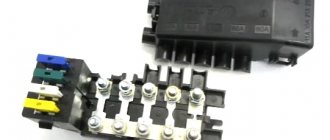
Relays and fuses on a KamAZ vehicle equipped with an engine with an electronic control system are installed behind the instrument panel cover (see Fig. Installing a fuse and relay box).
Fuse F5 is installed on the cab front panel (see Fig. Fuse F5).
Installing the fuse and relay box 1 - installing the relay behind the switch panel; 2 — installation of the relay behind the cover of the instrument panel compartment; 3 — windshield wiper relay; 4 - turn signal interrupter relay; 5 - fuse block (F2, F3, F4, F6); 6 - fuse F1 (generator, ECU, engine stop)
Fuse F5 1 - dryer cable; 2 — wire “Fuse-generator”; 3, 4 — fuse wires; 5 - to fuse block F4; 6 - jumper; 7 - wire “battery - fuse”; 8 - wire “Starter - fuse”
Installing a relay behind the switch panel 1 - ECU relay; 2 — generator excitation winding relay; 3 — fan drive clutch relay; 4, 5, 6, 7, 8 - see the Table of applied relays
Table of relays used
For KAMAZ engines with electronic fuel supply control system
Starter Interlock Relay
Parking brake relay
Installing the relay behind the instrument panel compartment cover 1 - relay for additional headlights; 2 — side light relay; 3 - fog lamp relay; 4 — rear fog lamp relay; 5 — high beam relay; 6 — low beam relay; 7 - switch relay; 8 — battery switch “+” relay; 9 — brake signal relay; 10 — reverse relay; 11 - sound signal relay
Fuses located in the fuse box (see Fig. Installing the fuse and relay box behind the instrument panel):
The windshield cleaning system is designed to wash and clean windshields to ensure vehicle safety.
It includes electric windshield wipers 27.5205 and windshield washers 1112.5208-01.
The electric windshield washer is controlled by a key switch and has an electric pump built into the washer reservoir.
Instrumentation system
As you might guess from the name, this system is designed to service various instrumentation, indicators and sensors. Instruments are located on the dashboard of the car, and sensors are located in its various components and mechanisms.
The electrical diagram of this system is as follows:
The numbers on the diagram indicate:
- fuel level indicator;
- fuel level sensor;
- fuse 13.3722 (7.5 A);
- coolant temperature indicator sensor;
- coolant overheat sensor;
- emergency oil pressure sensor;
- oil pressure indicator sensor;
- oil pressure indicator;
- 11 — blocks of warning lamps;
- coolant temperature gauge;
- generator;
- tachometer;
- speedometer;
- speedometer sensor;
I. to the instrument and starter switch
Fuse box
Photo - diagram
General designation
row F2
| 1 | Reserve |
| 2 | Low beam right, corrector |
| 3 | Low beam left |
| 4 | Rear fog light |
| 5 | High beam right, high beam warning lamp |
| 6 | High beam left |
| 7 | Reserve |
| 8 | Right side marker, instrument lighting |
| 9 | Left clearance |
| 10 | Fog lights |
| 11 | Central light switch, spotlight |
| 12 | Lighthouses |
| 13 | Sleeping place, engine compartment lamp, road train lights |
row F3
| 1 | Wheel lock, radio |
| 2 | Gas leak alarm (on gas vehicles) |
| 3 | Power take-off, daytime running lights, winch |
| 4 | Electromagnetic engine cooling clutch, reversing lights |
| 5 | Ground switch relay coil |
| 6 | Buzzer (sound signal), brake signal relay coil |
| 7 | Generator excitation winding, tire inflation |
| 8 | Courtesy lamps, glove compartment lighting, instrument cluster power supply |
| 9 | Pendant lamp socket, heater motors |
| 10 | Horns, "+" trailer sockets, brake lights |
| 11 | Driver blower fan |
| 12 | Reserve |
| 13 | Heated mirrors, heated seats |
row F4
| 1 | Reserve |
| 2 | Electronic speedometer, electronic tachometer |
| 3 | Tractor ABS |
| 4 | Trailer ABS |
| 5 | Instruments, electronic speedometer, electronic tachometer |
| 6 | Tractor ABS, engine brake relay (valve) |
| 7 | Trailer ABS |
| 8 | Gas level sensor (on gas vehicles) |
| 9 | Wiper power supply |
| 10 | Engine control unit power supply |
| 11 | Electric flare device |
| 12 | Reserve |
| 13 | Reserve |
series F6 (for KAMAZ engines)
| 1 | The engine control unit |
| 2 | The engine control unit |
| 3 | Diagnostic connector |
| Brake relay | |
| 4 | Warning lamps |
| 5 | Warning lamps |
| 6 | Air suspension control unit |
| 7 | Urea pump |
| 8 | Urea pump |
| NOx sensor | |
| 9 | Reserve |
| 10 | Reserve |
| 11 | Automatic transmission control unit |
| 12 | Retarder braking signal |
| 13 | Automatic transmission control unit |
row F6 (for CUMMINS engines)
| 1 | The engine control unit |
| 2 | The engine control unit |
| 3 | Diagnostic connector |
| 4 | Reserve |
| 5 | Air suspension control unit |
| 6 | Air suspension control unit |
| 7 | Dosing pump |
| 8 | Urea heating line relay |
| Dosing pump | |
| 9 | Reserve |
| 10 | NOx sensor |
| 11 | Automatic transmission control unit |
| 12 | Automatic transmission, retarder brake signal |
| 13 | Automatic transmission control unit |