3.9 / 5 ( 52 voices)
The UAZ-452 was originally created for the Soviet armed forces as a medical service vehicle, where it was therefore dubbed the “tablet” (the civilian nickname is “loaf”).
Therefore, the design of the mechanisms, including the transfer case, is simplified as much as possible.
During operation, the entire transmission system is unpretentious, which is confirmed by half a century of practice. The only recommendation from the manufacturer is to periodically check the oil level and check the fasteners.
In addition, if necessary, the front linkages should be adjusted and the lever axles should be lubricated on a preventive basis. This mechanical unit, including bearings, does not require any further maintenance or adjustment.
Device and how it works
The transfer case is a mechanism located in a separate housing made of gray cast iron. The assembly is divided vertically into a crankcase and a cover, which are connected by bolts. Both halves undergo joint processing, so it is impossible to install a part from another gearbox. The crankcase has a separate hatch for installing a power take-off. The oil-filled unit with the parking brake drum installed weighs 37 kg.
The transfer gearbox will only work correctly if it is correctly centered on the gearbox housing. For this, a 2-row angular contact bearing and a steel cylindrical cup are used. The gearbox shafts are mounted on ball and roller bearings, secured with nuts and retaining rings, respectively. The output shafts pass through sealing seals installed in the covers.
The drive shaft of the unit is the driven axis of the gearbox, which is equipped with a splined tip on which the gear is located. This part has 2 positions that allow you to get forward and reduced speeds. The shift drive is equipped with a special fuse that prevents the low range from starting until the front wheel drive is connected.
When the gear is connected to the gear wheel of the rear axle drive shaft, direct transmission is ensured. The gearbox device includes a special lever that allows you to move the gear to the side, engaging it with the gear of the intermediate shaft. In this position, the rotation speed of the driveshafts of the axle drives is reduced.
The design of the transfer gearbox has a movable gear wheel mounted on the middle shaft and controlled by a separate lever. This gear provides connection to the front wheel drive. When the gear is disengaged, the gear continues to rotate as it remains in contact with the rear axle drive gear. This operating principle is necessary to spray the oil in the crankcase.
The plant produced several modifications of the transfer gearbox, which differ in the module of installed gears. Because of this, the gear ratio changed - instead of 1.94 it became 1.47. It is possible to remake the old-style transfer case by replacing gears, since the housing design has remained unchanged.
On some cars there is an imported Hyundai Dymos transfer case (Dymos) with electrical control. The unit weighs 32.4 kg, provides direct and low gears (gear ratio 2.542). The unit is equipped with a controller that diagnoses the box and records error codes. The mechanical part of the imported box is very different from the Russian counterpart - instead of gears, a chain drive is used.
Rear axle drive shaft
What does the UAZ transfer case consist of, what are its features? This shaft is mounted on two ball bearings. To protect the element from axial movements, it is held in place by a rear bearing with a thrust ring and a cover. A gear is attached to the front of the shaft. Its inner crown has slots. The function of this gear is to drive the front drive axle. Internal splines are required to engage direct transmission in the transfer case.
A screw-type gear is also installed on the splines between the bearings. It serves as a drive for the speedometer. The rear part of the shaft is connected to the cardan shaft using a nut with a conical protrusion through a flange. If you tighten this nut, its conical protrusion will bend into one of the grooves that are cut into the threads and stop.
How to use
To change speeds, a lever is used that has 3 positions:
- extreme anterior, corresponding to direct transmission;
- average, at which the box is turned off;
- extreme rear to enable the lower row.
Before engaging a downshift, you must activate the front axle drive (using a separate lever). The switching diagram is printed on a special plate, which is attached to the instrument panel. The position of the control levers is slightly different on different UAZ models, but the far handle is always used to control the drive of the front wheels.
Before you start using the transfer case on your UAZ, you should carefully read the instructions. The low range can only be engaged with the clutch open and after the vehicle has come to a complete stop.
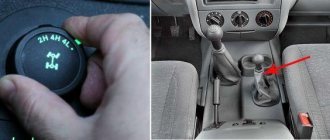
When using a Dymos box, switching is performed by a rotary washer having 3 positions:
- rear wheel drive only (2H);
- connection of all-wheel drive and direct transmission (4H);
- lower row and torque transmission to both axles (4L).
Location of switch devices on the UAZ dashboard
Dashboard of UAZ-31512 Dashboard of cars UAZ-31514, UAZ-31519 Dashboard of car UAZ-3153 Dashboard of cars UAZ-3741, UAZ-3962, UAZ-3909, UAZ-2206, UAZ-3303 Dashboard of cars UAZ-33036, UAZ-39094, UAZ-39095 Key position in the ignition switch of UAZ-31512 vehicles and the UAZ-3741 family:
- O - neutral position (fixed position);
- I-ignition is on (fixed position);
- II - ignition and starter are on (non-fixed position);
- III - the receiver is turned on (when it is installed; the position is fixed)
Key positions in the ignition switch of UAZ-31514, UAZ-31519, UAZ-3153 vehicles:
- O - everything is off (fixed position);
- I - ignition is on (fixed position);
- II - starter turned on (non-fixed)
How to disassemble and reassemble
Algorithm for removing the unit from the car:
- Disconnect the propeller shaft flanges from the transfer gearbox.
- Unscrew the attachment points of the transfer case to the gearbox.
- Separate the units by simultaneously removing the locking ring located on the intermediate shaft of the gearbox.
- Remove the gaskets from the mating surfaces.
- Remove the cover of the opening for installing the power take-off gearbox, and then dismantle the gear selection mechanism (together with rods and levers).
- Remove the handbrake drum secured with several screws. After this, you need to remove the rear propeller shaft drive flange.
- Remove the bolts securing the parking brake mechanism to the transfer gear housing. After this, you need to remove the mechanism.
- Remove the flange for installing the front axle drive shaft. Then you need to unscrew the front bearing cap.
- Remove the bolts connecting the crankcase halves. Disconnect the assembly, keeping all internal elements on the cover. It is not recommended to remove the covers and steel bearing cup.
- Disconnect the shift rod stopper and remove the elements using a soft hammer. At the same time, the shift forks are dismantled along with the clamps.
- Unscrew the speedometer drive gear lock.
- Using a screwdriver, remove the bearing retaining rings and then remove the transfer gear shafts.
- Remove the bearings from the shafts using a puller.
- Press out the drive shaft of the rear wheels, remove the oil deflector and the speedometer gear drive. After this, you need to remove the bearing with a puller.
- Disassemble the gear shift mechanism (if necessary).
- Carry out troubleshooting of parts, replace worn elements with new ones. If the housing is damaged, the transfer case must be replaced with a new one.
- Assembly of the unit is carried out in reverse order. It is necessary to install new original gaskets; the use of parts with increased thickness is prohibited.
Read also: Federal Security Service of Russia employee reviews
It is recommended to disassemble the imported Daimos box in a car service center, since repairs require special equipment. The unit is equipped with electric drives, so it is difficult to adjust the mechanism yourself.
UAZ-452. Repair of RK with passion. The final.
I went to the store and bought: both flanges, a speedometer cable, a fork for switching the rear axle and low range, and all the little things.
I started assembling the UAZ-452 transfer case.
To position the fork correctly, I had to turn the rod a little. Ten degrees.
Next, all the shafts on the cover are assembled. Well, at least that's what I do. It's more comfortable for me.
You can easily twist it. Check whether the gears mesh correctly when shifting.
Another joke from the Ulyanovsk concern. I bought new original flanges.
At the same time, the front axle drive flange along the neck is more or less polished. But they decided to pack the rear axle drive flange right after turning?!
Well, okay, there are risks after the through cutter. But there's a dog there! I'm shocked. At an enterprise that has no quality control department at all or what? Well, how can you put this on sale? The oil seal won’t last even a week on such a surface...
I had to clamp the flange into a lathe, grind and polish it by hand.
Polished from above by me, from below by Ulyanovsk crooked factory workers.
Yes, also pay attention to how crookedly the blank of the upper flange is turned after casting. Balancing there and so on. Not. Haven't heard...
And here, by the way, is the old flange. I used a marker to paint over it so that it would be clear where the seal journals work.
Here I think everything is clear. As they say - NO COMMENT.
Next, the handbrake assembly. Let me remind you that, as such, it was not in working order.
We wash, clean, completely disassemble.
It is imperative to disassemble, clean and lubricate the handbrake release cylinder. It usually boils into rubbish and is poorly mixed and mixed.
After cleaning, I fill its guts with an imported lubricant that is non-washable and resistant to aggressive environments. As a rule, it works for a long time and reliably.
And then, we assemble the entire handbrake assembly.
Then the handbrake drum is attached and the spread of the brake pads is adjusted. Everything spins in all positions of the switches and is finally assembled.
At this point, the overhaul of the UAZ-452 transfer case can be considered complete.
How to fill oil into transfer case
Procedure for changing oil in a Daimos type box:
- Warm up the fluid in the transfer gearbox by driving the car for 15-20 km. Replacement is carried out after 45 thousand km or once every 2 years.
- Wipe the box housing around the filler and drain holes.
- Place a container designed for 2-2.5 liters of liquid.
- Unscrew both plugs and drain the oil from the crankcase.
- Wait 10-15 for complete drainage, replace the plug with a new O-ring.
- Fill the crankcase with 1.8 liters of fresh 75W-85 API GL-4 oil through the filler hole.
- Close the hole with a plug with a new O-ring.
Replacing the bearing and oil seal
The design of the transfer case allows the replacement of the rear wheel drive shaft seal without dismantling the unit. To do this, you need to disconnect the driveshaft and remove the parking brake mechanism. The old oil seal is removed using a slotted screwdriver.
Replacing bearings without removing the gearbox is not recommended, since the parts are installed with interference. If the bearings are removed from their housings by hand, the gear housing must be replaced with a new one.
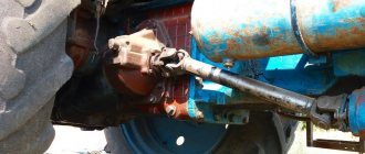
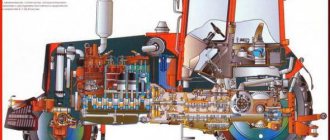
The vehicles produced at the plant in Ulyanovsk are classified as off-road vehicles; it is no coincidence that the package includes a UAZ transfer case. The mechanism is designed to distribute the torsional impulse of the motor to the wheels. The design increases the number of transmission gears and torque when moving off-road.
Initially, UAZ vehicles, including the Bukhanka, were developed for the needs of the army. That's why the transmission is simple, unpretentious and requires minimal maintenance. Thanks to these qualities, the car appealed to lovers of hunting, fishing, and tourism. In addition, the transport is suitable for transporting goods in the absence of roads.
Transfer case UAZ-452 “Loaf”:
Razdatka
Photo handout UAZ repair, modification, tuning. Photo of GAZ, Gazelle, Sobol distribution box repair, modification, tuning.
Tuning UAZ and GAZelle 4x4. Repair of driving axles. Repair of UAZ and GAZ gearboxes and transfer cases. Aluminum body and interior upholstery. Repair of UAZ Patriot, Hunter, Loaf (2206), Tadpole, 469, 31514, 31512, Tablet, Gazelle, Sable 4x4, Barguzin.
- Auto-tuning of individual components Off-road tuning
- Engine
- Additional equipment for SUVs
- Additional equipment universal
- Manufacturing of attachments
- Suspension
- Steering
- Exhaust system
- Cooling system
- Brake system
- Transmission Rear axle
- Gearbox - tuning and repair
- Razdatka
+7 (926) 572-1494 Odintsovo, Moscow region
The nearest settlements for the repair of Gazelle
Settlements and territories for servicing and repairing UAZ and Gazelle vehicles at our service center.
- Repair of Gazelles from Vnukovo.
- Service to Patriots from Kuntsevo.
- We are doing Hunters not far from Solntsevo.
- Gazelle from Tolstopaltsevo.
- For Patriot from Aprelevka, a car service is nearby.
- UAZ Pickup is a rarity in Barvikha.
- Vlasikha car service.
- Delivery from Golitsyno.
- 3 km from Dubka.
- 10 km from Zhavoronka.
- Not far from Zarechye at all.
- UAZ overhaul for Zvenigorod.
- We accept orders from Krasnoznamensk.
- Very close to Krekshino.
- On the way and Kubinka to Moscow
- Next door is Lesnoy Gorodok
- Repairing Gazelles from Nazaryevo
- Car service right in Odintsovo
- On the way to Moscow from Perkhushkovo
- Rublevo-Uspenskoe highway
- We are located between Minskoe highway and Mozhaiskoe highway
- People come to us from Kievskoye Highway
The device of the UAZ “Bukhanka” transfer case
The UAZ Bukhanka transfer case is a two-stage design without a differential between the axles. The mechanism is also equipped with a neutral message and switchable front wheels. The components are placed in a tray made of cast iron and equipped with a plug. The pallet is attached to the back of the box through the holes of the plates. In addition, the components of the handbrake are also attached here. The main and transition shafts of the box, the drives of the front and rear wheels, are secured by bearings. Between the supports that facilitate the rotation of the shaft, a gear is placed that drives the speed measuring device. The top of the box has an inspection hatch protected by a shutter.
Dymos transfer case for UAZ (finishing):
The control contains two rods with forks attached to a plug. The fork-shaped rods work in tandem with the drive gear and the activation gear for the front pair of wheels. Two control rods are connected to the forks by means of movable pins. There is also a blocking sphere that prevents the activation of low gear when the front wheels are not working.
By activating direct transmission, the UAZ Bukhanka transfer case acts in a similar way so that the main gear moves into the slot of the gear shaft of the rear pair of wheels, transporting the impulse directly. Activating the low gear shifts the main gear so that the impulse is transported to the intermediate shaft and to the gears that drive the axle. Activation of the low stage is only possible after the machine has come to a complete stop.
UAZ Bukhanka transfer case diagram:
Checking the transfer case
The advantage of the unit that distributes the torque impulse is that the device requires minimal intervention and maintenance. Manipulations consist of monitoring the level and changing the lubricant, inspecting connections for damage. Before working with the box, the product is cleaned. This helps detect hidden cracks and leaks. If such symptoms are detected, they find out what the cause of the phenomenon is. Faulty parts are replaced, as a rule, these are sealing elements and oil seals.
Read also: Location of seats in a Ford minibus
After cleaning and visually inspecting the surface of the transfer case, check the lubricant level in the product. If there is not enough liquid, the substance is added. At the same time, check the lubricant in the gearbox; the value corresponds to the lower edge of the filling hole. If the fluid level in the transfer case is low, but is high in the gearbox, topping up is not necessary, since the total amount of the substance has not changed.
A detailed inspection of the box involves dismantling the product. After washing and air drying, the unit is inspected. The pallet and plugs are checked for cracks and chips. Oil seals and seals are replaced with new ones.
Changing the oil in the UAZ transfer case:
They check that the condition of the working parts on the shafts and splines corresponds to the standard, so that the gear teeth are not worn or chipped. Even if the damage is small, the product must be replaced. Attention is paid to the bearings; abrasions on the ring tracks are not acceptable. They also check separators, spheres, rollers, etc. Gaps, fragments, knocking, uneven movement are a signal to change the product.
The rods and forks become jammed and deformed, the elasticity of the spring elements is lost, and then the products are replaced. In addition, you should pay close attention to switching when the transfer case levers of the UAZ Bukhanka stick and jam. The coupling teeth are checked for damage. The weak link of the differential is the satellite. Small defects force the product to be polished, or in the worst case, replaced.
Weaknesses: common faults
Thanks to its simple design and elementary operating principle, early repair of a UAZ transfer case is rather an exception than a rule. By the way, such an exception is often the new (chain) transfer case, which is due to the not fully thought out location of its engine. However, even the mechanics break down in some cases.
More often - due to careless actions of the driver. The fact is that the transfer case cannot be used in normal driving conditions. It is indispensable off-road for overcoming momentary obstacles (“spot” operation). If you change the load under normal conditions, the mechanism wears out very quickly.
In addition, a UAZ transfer case overhaul may be required (top 3 most common breakdowns):
- when consumables wear out (oil seals through which lubricant leaks);
- mechanical damage (it’s hard not to notice them - the box begins to make uncharacteristic loud knocks);
- damage, physical wear or loosening of the bearings (a dangerous malfunction that threatens to replace the entire assembly, so it is better not to delay the repair of the UAZ “Bukhanka” or “Hunter” transfer case in such cases).
It’s rare, but it happens that gear teeth or even the shafts themselves break. Then worn parts need to be replaced as soon as possible. Repairing any automotive component will always cost significantly less than replacing it completely.
Causes and troubleshooting
The design of the UAZ gearbox is reliable, trouble-free and durable. However, problems with equipment occur due to errors in use and violation of established regulations.
| Source and symptoms | What to do |
| Exceeding the permissible hum level of a working device | |
| Erasing the gear teeth of the box. | Replace worn out box items. |
| Weak fastening of the transfer case to the box, or reduced fixation of the bearing caps. | Tighten the fasteners, if the symptom recurs, dismantle the product and eliminate the defect. |
| Bearings are worn out. | Replace erased items. |
| Saturation of the working fluid with wear products from the box. | Remove the pan, wash it, change the oil. |
| Incorrect oil used, low fluid filling level. | Change the working fluid, set the desired level. |
| Carrying out repairs to replace gears, without selecting a product to minimize noise. | Check the gears for noise and replace them with the required ones. |
| Switching steps is difficult | |
| Different wheel wear. | Replace with wheels with the same tread and equalize the internal pressure. |
| The joints of the longitudinal projections of the main and the mediator shaft are jammed. | Sand the areas with burrs; if that doesn’t help, change the elements. |
| The drive gear has damage on the teeth of the small ring. The shift fork rod is bent. | Sand the damaged areas, straighten the rod, if that doesn’t help, change the element. |
| The switch rods are stuck on the axle. | Separate the parts, clean the axles and pipes, coat with lubricant, and connect the product again. |
| Spontaneous speed shutdown | |
| Erasing the teeth of the gears of the box. | Replace worn out box items. |
| The box bearings are worn out. | Replace worn box elements. |
| A large gap in the articulation of the shaft and gear. | Select the gear according to the size of the longitudinal protrusions. |
| The transmission is unable to engage because the mechanism is bent or there is damage to the gears and cylinders. | Correct bends, sand damage, or replace parts. |
| Poor functioning of the locking mechanism, loss of elasticity of the spring mechanism, abrasion. | Replace erased items. |
| Leakage of working fluid | |
| Violation of the integrity of the sealing elements of the pan, bearing caps, and the transfer case’s articulation with the gearbox. | Replace sealing elements. |
| Weak fastening of the cover, bearing, pan, joints. | Tighten connections. |
| Violation of the integrity of the shaft seals. | Replace the damaged element. |
| Violation of the integrity of the tray or lid. | Replace the damaged element. |
| The plugs of the switching rods, switching rods, and the plugs of the front bearing of the middle shaft fall out or are broken. | Change the plugs. |
| Bearings are damaged | |
| No, or a small amount of lubricant. | Change or add fluid. |
| Demolition of cages and bearing rings due to abrasive. | Change the elements, dismantle and wash the pan, change the working fluid. |
| Excessive shaft bearing friction. | Disconnect the element, clean the product, and coat it with lubricant before reassembling. |
The distributor needs careful handling and periodic inspection. Often, the reason for the breakdown is trivial driving on wheels with a violation of the pressure regime. Continuous use of the front pair of wheels is not allowed; the product is used as needed. Operation is affected by the use of spare parts that do not meet the required quality.
Repair of UAZ Bukhanka transfer case
Serious repairs to the UAZ transfer case are rarely performed. As a rule, to restore normal operation, adjusting the product and lubricating problem areas is enough. If repairs cannot be avoided, then the operation to return the box to its former functionality is done in strict order.
- Dismantling the transfer case;
- Disassembling the transfer case;
- Fault detection;
- Troubleshooting (replacement, restoration of parts);
- Transfer case assembly;
- Installing the transfer case in place;
- Functionality check and configuration.
Read also: How to set the ignition on a KamAZ
Before carrying out work, select the necessary tools; for this, find out the type and type of transfer case. Functionally, repair is the replacement of damaged parts with new ones, for this reason more attention is paid to the rejection stage.
- Oil seals (changed during disassembly, regardless of the degree of wear);
- Gears (parts cannot be repaired due to the loads they experience);
- Forks and splines (elements affect the quality of work and safety);
- Bearings;
- Protective casing (if cracks or chips are detected, the part is replaced).
UAZ transfer case control mechanism:
Applicability of spur transfer cases with a speedometer drive of 624 revolutions/kilometer on the UAZ.
For vehicles of the UAZ-3151 family:
— axles with final drives: 469-1800020 — reduction 1.94. — single-stage bridges: 31512-1800020 — reduction 1.94, 31514-1800022-50 with reduction 1.47.
For vehicles of the UAZ-3160 family:
— with a four-speed gearbox: 3159-1800021-10 with a reduction of 1.94 and 3160-1800020-02 with a reduction of 1.47. — with a five-speed gearbox: 3159-1800021-60 with a reduction of 1.94 and 31603-1800020 with a reduction of 1.47.
For cars of the UAZ-3741 family of wagon layout:
— with single-stage bridges: 3741-1800020 — reduction 1.94. Information: auto.kombat On our website, UAZ spur transfer cases with standard and increased reduction gear numbers are available for order: Transfer case (RK) spur UAZ 469, HUNTER Transfer case (RK) UAZ-452
Installation of the UAZ RK, with an increased number of downshifts, allows
- confidently overcome routes that require increased cross-country ability at low speeds;
- eliminates the moment of slipping when driving off-road, preserving the clutch resource.
Quality of RK parts
- Each UAZ RK is assembled using new factory parts from UAZ OJSC
- high-quality assembly and installation of RK parts, eliminates the “overshoot” of a lower gear;
- each pair is tested for noise and contact patch on a noise-control machine, so the set of reduction gears is absolutely silent;
- transfer cases are made on the basis of factory RCs using sets of reduction gears RC UAZ "Avtogur73", made of structural alloy steel, 18ХГТ.
This grade of steel is used for the manufacture of parts operating under impact loads, which require increased strength, high surface hardness and core toughness.
The use of this grade of steel provides high levels of bending and contact endurance of teeth. In simple words: parts made of this grade of steel, having undergone a certain processing process, are strong, durable and hard, but at the same time they are capable of absorbing mechanical energy in the process of deformation and destruction under the influence of impact load, i.e. do not collapse. We can also modify your RK with a set of reduction gears. The cost of the work is 5,000 rubles + shipping costs. Article: Maintenance. Disassembling the transfer case
UAZ Bukhanka transfer case control
The UAZ Bukhanka transfer case is controlled remotely from the driver’s cab. The levers used to manipulate the car are located on the right side of the user. The upper rod activates and deactivates the front pair of wheels of the car, has two positions: top (the bridge is activated), bottom (the bridge is deactivated).
Position of the transfer case levers of the UAZ Bukhanka:
The location of the transfer case levers on the UAZ Bukhanka is possible in three options. First, the main gear is activated, middle (zero), the main shaft does not rotate, second, low gear is activated.
In order to avoid damage to the transfer case if the gear is incorrectly activated, a locking device is provided. The product is fixed in the cover of the gear change rods. Thanks to the fuse, the low gear is activated after the front pair of wheels is activated. Meanwhile, the front pair of wheels is not activated when a downshift is engaged. A solution has been implemented with a ball acting as a lock. The sphere in the cover prevents the rods from moving and deactivates the front pair of wheels until the rods are put into downshift. The lock prevents the driveshaft and rear pair of wheels from being overloaded.
There are single-lever control elements, one rod alternately activates: the front pair of wheels, zero, then low stage.
The UAZ-452 was originally created for the Soviet armed forces as a medical service vehicle, where it was therefore dubbed the “tablet” (the civilian nickname is “loaf”).
Therefore, the design of the mechanisms, including the transfer case, is simplified as much as possible.
During operation, the entire transmission system is unpretentious, which is confirmed by half a century of practice. The only recommendation from the manufacturer is to periodically check the oil level and check the fasteners.
In addition, if necessary, the front linkages should be adjusted and the lever axles should be lubricated on a preventive basis. This mechanical unit, including bearings, does not require any further maintenance or adjustment.
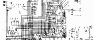
Names of positions in the UAZ control pictures
- hazard switch. When you press the switch button, the lamps of all indicators and turn signal indicators, the signal lamp for turning on the turn indicators (item 6) and the indicator lamp inside the switch button simultaneously operate in a flashing mode.
- speedometer. It shows the speed of the car in km/h, and the counter installed in it shows the total mileage of the car in km.
- fuel level indicator in the tank. Each tank has its own indicator sensor (except for additional tanks).
- brake system emergency warning light (red). Lights up when the tightness of one of the hydraulic drive circuits to the brake mechanisms is broken.
- parking brake activation warning light (red).
- turn signal indicator light (green). Operates in flashing mode when the turn signal switch or hazard warning light switch is turned on.
- warning lamp for emergency overheating of the coolant in the radiator.
- signal lamp for turning on the high beam headlights (blue).
- coolant temperature indicator in the engine cylinder block.
- oil pressure warning light. Lights up when the oil pressure in the engine lubrication system drops to 118 kPa (1.2 kgf/cm2)
- oil pressure indicator in the engine lubrication system.
- voltmeter. Shows the voltage in the vehicle's on-board network.
- cigarette lighter To heat the cigarette lighter coil, press the handle of the insert, push it in until it locks into the body and release the handle. When the required heating temperature of the spiral is reached, the insert automatically returns to its original position. Forced holding of the insert in a recessed position is not allowed.
- lighting lamp (installed on UAZ-31512, on other models a courtesy lamp is installed)
- lighting switch. On some models the switch is located next to the lampshade.
- carburetor throttle control handle.
- switch for fuel level sensors in tanks.
- rear fog light switch with integrated warning light
- fog light switch.
- combined ignition and starter switch (see Fig. 1.22 and 1 23). The key from the ignition switch of UAZ-31514, UAZ-31519, UAZ-3153 vehicles is removed only in position III, and the locking mechanism is activated, blocking the steering shaft. To lock the steering when parked, set the key to position III, remove it and turn the steering wheel in any direction until you hear a click, indicating that the tongue of the locking device coincides with the groove of the steering wheel shaft locking sleeve. When unlocking the steering, insert the key into the ignition switch and, rocking the steering wheel left and right, turn the key clockwise to position 0. In order to eliminate cases of erroneous activation of the starter while the engine is running (key position II), a lock is used in the design of the ignition switch mechanism , making it possible to restart the engine only after returning the key to position 0. It is not allowed to turn off the ignition and remove the key from the ignition switch while the car is moving. Stopping the engine will lead to loss of braking efficiency, and when the ignition key is removed, the steering shaft is blocked by an anti-theft device and the car becomes uncontrollable
- central light switch. It has three fixed positions, the first is everything is off; second - the side lights are on; third - the side lights and low or high beam are on (depending on the position of the light switch). By turning the knob, the intensity of the lighting of the devices is adjusted. On UAZ-3153, UAZ-33036, UAZ-39094, UAZ-39095 vehicles, a key switch and a separate instrument lighting switch are installed.
- carburetor air damper control handle.
- wiper and washer switch handle (not installed on vehicles with multifunction steering column switches). Rotating the handle turns on the wiper, pressing the handle in the axial direction turns on the washer.
- thermal fuse button in the lighting circuit.
- heater fan motor switch. It has three positions: off, low motor speed on, high speed on; rotation of the heater fan motor.
- levers of multifunction steering column switches (for lever positions, see Fig. 1.24).
- instrument lighting switch. When the outdoor lighting is turned on, rotating the handle turns on the lighting of the devices and adjusts their brightness.
- ashtray.
- hatch cover to the hydraulic clutch reservoir.
Features of the box
The UAZ-452 transfer case is the heart of the car’s transmission. It transmits dynamic force to the front and rear axles and has 2 operating modes: direct and reduction (with a gear ratio of 1.94).
The latter helps create more efficient traction when overcoming off-road conditions and terrain folds.
During assembly, the operating gears of the transfer case are mounted taking into account the noise emitted during rotation. When a worn gear is replaced with a new one during operation, an increased level of noise often occurs in the gearbox, which is not dangerous and usually goes away over time.
______________________________________________________________________________
______________________________________________________________________________
Transfer case for UAZ-452 cars
The transfer case (transfer case) of the UAZ-452 is designed to transmit torque to the front and rear axles and has two gears: direct with a gear ratio of 1.00 and a reduction gear with a gear ratio of 1.94.
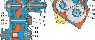
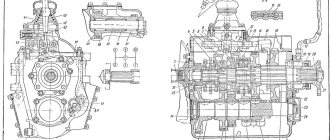
Fig.1. Transfer case (transfer case) UAZ-452
1 — driven shaft of the gearbox; 2 — driven shaft bearing; 3 — gear for downshifting and rear axle; 4 and 7 — rear axle drive shaft bearings; 5— driven gear of the speedometer drive; 6 — speedometer drive gear; 8 - cover; 9 — rear propeller shaft flange; 10 — rear axle drive shaft; 11 and 24 - intermediate shaft bearings; 12 — intermediate shaft; 13 — front axle engagement gears; 14 — bridge cover; 15— front axle drive shaft; 16 — front shaft drive bearings, 17 — crankcase cover, 18 — crankcase gasket; 19 — transfer case housing, 20 — plug; 21 - cover; 22 — oil seal; 23 — front driveshaft flange; 25— plug; 26 — bearing cup; 27—box cover; 28—switching mechanism cover, 30—breather; 29 - upper crankcase hatch cover, 31 - oil filler plug The reduction gear allows you to significantly increase the traction force on the wheels under difficult operating conditions of the vehicle (off-road, deep snow, climbs). The UAZ-452 transfer case is shown in Fig. 1. The drive shaft of the transfer case is the driven shaft 1 of the gearbox included in it. The sliding gear 3 for engaging the rear axle and downshift is installed on the splines of this shaft. When this gear moves backward and connects it with the internal teeth of the rear axle drive shaft 10 gear, the rear axle will be engaged (gear ratio 1.00), and when it is moved forward and engaged with the intermediate shaft gear 12, a downshift will be engaged (gear ratio 1, 94). The intermediate shaft of the UAZ-452 transfer case, made integral with the reduction gear, rotates on two bearings, the front of which is roller, and the rear is ball. The sliding gear 13 for engaging the front axle moves along the splines of the transfer case shaft. When moving backward along the splines, this gear meshes with the gear of shaft 15 of the front axle drive. Both shafts are mounted on ball bearings. All UAZ-452 transfer case shafts are protected from axial movements by bearing caps and thrust rings installed in the grooves of the outer rings of ball bearings. The drive gear 6 for the speedometer drive is installed on the rear axle drive shaft. All gears of the UAZ-452 transfer case are straight-cut. When assembled at the factory, the gears are selected for noise. If for some reason during operation one of the gears is replaced with a new one, then such a transfer case may experience slightly increased noise during operation. Such noise is acceptable and is not dangerous for the transfer case. The bearings of the UAZ-452 transfer case do not require any adjustment in operation.
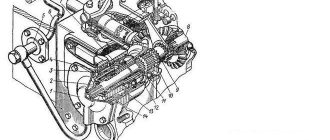
Fig.2. Transfer case control mechanism UAZ-452 1 — front axle engagement lever; 2 - lever for engaging the rear axle and downshifting in the transfer case; 3 — shaft for engaging the rear axle and downshift; 4 — front axle activation shaft; 5 - cracker; 6 — spherical bushing; 7 — spherical bushing body; 8 and 9 — intermediate levers; 10 — adjusting rods; 11 — front axle engagement rod; 12 — rod for engaging the rear axle and downshift in the transfer case; 13 - protective cuff Control of the transfer case of UAZ-452 vehicles, shown in Fig. 2, is remote. The control levers are located to the right of the driver, in front of the engine hood. The upper lever 1 is used to turn the front axle on and off and has two positions: forward when the front axle is turned on, and rear when the axle is turned off. Lower lever 2 is designed to change gears in the transfer case of the UAZ-452. It can be installed in three positions: forward when direct gear is engaged, neutral (middle) position in which the driven shaft does not rotate, and rear when downshift is engaged. Due to the presence of a locking device (lock) installed in the cover of the gearshift rods, a downshift can only be engaged after the front axle is turned on, and the front axle cannot be turned off when the downshift is engaged. Figure 3 shows the lock and the position of the rods when engaging the gears and the front axle.
Fig.3. Lock of the switching rods of the UAZ-452 transfer case a - position of the rods when engaging direct transmission (rear axle); b — position of the rods when downshifting and the front axle are engaged; 1 — front axle switch lever; 2—lever mounting pin; 3 — rod of the front axle activation lever; 4 — lever for downshift and rear axle; 5 — ball-lock; 6 — cover of the switching mechanism; 7—rod of the downshift lever and rear axle Figure 3a shows the position of the UAZ-452 transfer case rods when the rear axle is engaged (rod 7) and the front axle is disengaged (rod 3). At the position shown in Fig. 3b - the rods have moved to a position in which the front axle is engaged by rod 3, and downshift is engaged by rod 7. The locking ball 5 installed in the cover does not allow moving the rod 3 and disabling the front axle until the downshift is turned off by the rod 7. The lock is designed to prevent overloading of the driveshaft and rear axle parts. The front axle should be engaged when driving on a difficult road (mud, sand, snow, etc.). It is not allowed to engage the front drive axle when the front wheels are disabled. The position of the UAZ-452 transfer case shift levers is shown in Fig. 4.
Fig.4. Diagram of the position of the shift levers of the UAZ-452 transfer case a - front axle (upper lever); b — gear shift (lower lever); I—direct transmission; II - neutral position; III - reduction gear The spherical bushing 6 (see Fig. 3) of the upper shaft support and the bushing of the intermediate lever axis are made of plastic I and do not require lubrication. The lower ball joint is filled with graphite grease during assembly and additionally lubricated only during repairs or if squeaking occurs.
Front control rods 10 are adjusted in length using threaded forks. To adjust the position of levers 1 and 2, unpin and remove the finger from the rod fork connected to lever 1; set the rod (in the transfer case cover of the UAZ-452) to the rear axle engagement position, and lever 1 to the position corresponding to this gear. By rotating the fork, set the required rod length, align the holes in the rod fork and the lever, insert a pin and pin it. The position of lever 2 is adjusted in the same way. During the first maintenance (TO-1), the UAZ-452 transfer case housing is checked by inspection; If traces of grease are found on it, check the oil level and eliminate the problem. The oil level should be located at the lower edge of the filler hole. When refueling, do not rotate the shafts, as oil will stick to the gears and enter the crankcase in more quantities than required. This may cause oil to leak through the seal while the vehicle is running. At TO-1, check the oil level in the transfer case housing and, if necessary, top up. During the second maintenance of the UAZ-452 transfer case (TO-2): - Inspect the tightness, condition and fastening of the UAZ-452 transfer case and its drive. Remove the propeller shafts and tighten the nuts securing the flanges on the transfer case shafts (front and rear). Tighten the nuts and replace the driveshafts. When cottering, it is not allowed to unscrew the nut to ensure that the slot on it coincides with the hole on the shaft. To do this, you just need to tighten the nut. Clean the breather from dust and dirt and blow it out. Change the oil in the crankcase. If the oil is heavily contaminated or there are metal particles in it, the crankcase should be flushed with kerosene before adding fresh oil. To do this, you need to pour 0.8-1.0 liters of kerosene into the crankcase, raise the wheels, start the engine and let it run for 2-3 minutes, after which the kerosene is drained and fresh oil is added.
______________________________________________________________________________
______________________________________________________________________________
- Clutch and gearbox UAZ Hunter
- Transfer case and driveshafts UAZ Hunter
- Drive axles UAZ Hunter
- Adjusting the steering mechanism of the UAZ Hunter
______________________________________________________________________________
______________________________________________________________________________
- Checkpoint UAZ-Patriot
- Razdatka UAZ-Patriot
- Drive axles UAZ-Patriot
- UAZ-Patriot suspension
- Steering UAZ-Patriot
- UAZ Patriot power steering faults and their elimination
- Components of the UAZ-Patriot hydraulic brake drive
- UAZ-469 engine and its main parts
- Gearbox UAZ-469
- Drive front and rear axles of UAZ-469
- Clutch of UAZ-469 cars
______________________________________________________________________________
- Cylinder block and timing belt for UAZ-31512, 31514 engines
- Front and rear suspensions UAZ-31512, 31514
- Operations for assembly and disassembly of UAZ-31512, 31514 bridges
- Steering UAZ-31512, 31514 and its parts
- Brake system UAZ-31512, 31514
- Gearbox UAZ-452
- UAZ-452 clutch and its parts
- Transfer case UAZ-452
- UAZ-452 bridges and its components
- Gearbox UAZ-3909, UAZ-2206
- Cardan transmission UAZ-3909, UAZ-2206
- Front axle UAZ-3909, UAZ-2206
- Brakes UAZ-3909, UAZ-2206
- Clutch UAZ-3303
- Transfer case UAZ-3303
- Rear axle UAZ-3303
- Steering of UAZ-3303
- Cylinder block and crankshaft ZMZ-409
- Timing belt and valves ZMZ-409
- Lubrication system ZMZ-409
- Cooling and power system ZMZ-409
- Parts of the UMZ-421, UMZ-4218 cylinder block
- Timing belt and valves UMZ-421, UMZ-4218
- Lubrication system UMZ-421, UMZ-4218
- Cooling system UMZ-421, UMZ-4218
- Fuel system UMZ-421, UMZ-4218
Unit repair and maintenance
Signals for repairs can be:
- Oil leak.
- Increased noise and vibration.
- Difficulty switching from one position to another.
- Spontaneous loss of the switched on operating mode.
Although often, to fix problems, it is enough to just adjust the fasteners or lubricate problem areas and points. If this does not help, the car must be driven into an inspection pit or overpass, after which technological operations must be carried out in strict sequence.
Repair stages:
- dismantling and disassembling the box;
- failure detection;
- elimination of the causes of malfunctions (replacement or restoration of parts);
- assembly, installation in a regular place, adjustment.
Multifunction steering column switches
a - the turn signal and headlight switch lever has the following positions:
- I-direction indicators are off; the low beam of the headlights is on if the headlights are turned on by the central light switch;
- II — left turn indicators are on (non-fixed position);
- III — left turn indicators are on (fixed position);
- IV — right turn indicators are on (non-fixed position);
- V — right direction indicators are on (fixed position);
- VI (pull) - the main beam of the headlights is on, regardless of the position of the central light switch (non-fixed position);
- VII (from myself) - the main beam of the headlights is on if the headlights are turned on with the central light switch (fixed position);
b - the windshield wiper and washer switch lever has the following positions:
- I—windshield wiper and washer are turned off;
- II — intermittent operation of the windshield wiper is switched on (non-fixed position);
- III — intermittent wiper operation mode is turned on (fixed position);
- TV — the constant mode (low speed) of the windshield wiper operation is turned on (fixed position);
- V — the constant mode (high speed) of the windshield wiper is switched on (fixed position);
- VI (pull) - the washer and windshield wiper are on (non-fixed position);
- VII, VIII - not used