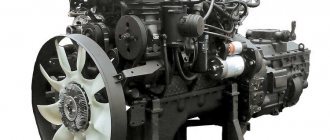
Parts of the cylinder block and crankshaft of the D-144 diesel engine
The D-144 diesel engine installed on the T-40 tractors is a four-stroke, non-compressor, air-cooled engine with direct fuel injection.
The diesel engine includes: a crank mechanism, a gas distribution mechanism, an air and fuel supply system, a lubrication system, a cooling system and a starting device.
D144 diesel crank mechanism
The crank mechanism (Fig. 2) serves to convert the reciprocating movement of the pistons into the rotational movement of the crankshaft.
The pistons are acted upon by gas pressure forces arising from the combustion of fuel in the cylinders. Through a connecting rod, pivotally connected to the piston and the crankpin of the crankshaft, the force is transmitted to the crankshaft 16.
The flywheel 11 mounted on the crankshaft serves to reduce the uneven operation of the diesel engine and transmit torque to the tractor transmission through the clutch.
To ensure normal operating conditions for the parts of the crank mechanism of the D-144 engine of the T40 tractor, during operation it is not allowed:
— loading an insufficiently heated diesel engine; — long-term operation when the diesel engine is overloaded; — diesel operation with oil pressure below 0.15 MPa (1.5 kgf/cm2); — diesel engine operation at oil temperature in the line above 120° and below 40°C; — prolonged operation of the diesel engine at idle, causing coking of the piston rings; — operation of a diesel engine without a fan casing and deflectors or when they do not fit tightly to the mating surfaces; — diesel operation on non-recommended types of oil; — operation of a diesel engine without an air cleaner, with a faulty air cleaner or air leakage through the connections of the suction pipelines; — diesel engine operation with interruptions, abnormal knocking and smoky exhaust.
Fig.1.
Diesel engine D-144 of the T-40 tractor 1 - fan drive drive pulley; 2 - generator; 3—fan; 4 — front deflector; 5 — cylinder head; 6 - nozzle; 7 — inlet pipeline; 8 — exhaust pipeline; 9 - cylinder; 10 - middle deflector; 11 — flywheel housing; 12 — fuel filters; 13 — diesel crankcase; 14 — oil dipstick; 15 — oil sump; 16 — connecting rod; 17 - crankshaft
Rice. 2. Crank mechanism of the D144 engine
1- fan drive drive pulley; 2—special bolt; 3 — oil pump drive gear; 4 — distribution drive gear; 5 — connecting rod bearing shell; 6 — connecting rod; 7 - piston; 8 — oil scraper ring; 9 — compression rings; 10— main bearing shell; 11 - flywheel; 12 — cuff; 13 - ball bearing; 14 — rear oil deflector; 15 — connecting rod bolt nut; 16 - crankshaft; 17 — counterweight; 18 — front oil deflector
The main part of the core of the D-144 engine of the T-40 tractor - the cylinder block is usually a cast iron or aluminum casting of complex shape.
The cylinder block combines the cylinder liners, the crankshaft bearings and the bearings of the gas distribution mechanism parts. The lower halves of the crankshaft supports are attached to the crankcase block from below.
The lower part of the cylinder block is covered by an oil pan, which can be lightweight or load-bearing. The front part of the crankcase block houses the drive for the gas distribution mechanism and auxiliary systems.
The rear part of the engine cylinder block is connected to the crankcase of the transmission components.
Air-cooled engines do not have a single cylinder block. Their cylinders are separate, removable with radiator fins on the outside to improve heat dissipation.
The cylinder head of the D-144 engine of the T-40 tractor is a casting made of aluminum alloy, but can also be cast iron.
The diesel cylinder head contains valves and other parts of the gas distribution mechanism, gas exchange channels, and seats for fuel injectors. In addition, the cylinder head can accommodate an undivided or split type combustion chamber.
The cylinder heads of air-cooled engines are individual and have an external radiator.
When disassembling for repairs, the cavities of the crankpins of the crankshaft should be cleaned. To do this, you need to pull out the cotter pins and unscrew the screw plugs.
The effectiveness of centrifugal oil cleaning in the cavities of the connecting rod journals of the D-144 crankshaft of the T40 tractor largely depends on following all the rules for maintaining the lubrication system, as well as on proper storage of oil and its filling into diesel.
If the recommended rules are not followed, the cavities of the connecting rod journals quickly fill with deposits, and oil purification in them stops.
In case of a drop in power, strong smoke and gases escaping through the exhaust pipe, difficult starting, a drop in oil pressure in the line below 0.15 MPa (1.5 kgf/cm2), when abnormal knocking noises occur associated with a malfunction of the crank mechanism, also with a large If the crankcase oil burns out, the diesel engine should be disassembled and inspected. Disassemble the diesel engine indoors.
The disassembled D-144 diesel engine is inspected and checked, taking into account what malfunctions were observed in its operation before disassembly.
So, for example, if a diesel engine smoked heavily, consumed a lot of oil, or there was a strong release of gases from the exhaust pipe, a drop in power was observed, or difficult starting occurred, it is necessary to check the condition and degree of wear of the piston rings, pistons and cylinders.
If the pressure indicator showed low or zero oil pressure in all operating modes, then before disassembling the diesel engine, you should check (if necessary, correct or replace) the pressure indicator and make sure that the oil receiver mesh is clean and the pressure reducing valve of the oil pump and the centrifuge are in good condition.
Only after these checks can you begin to disassemble the main and connecting rod bearings to inspect the rubbing surfaces, determine the gap in them and troubleshoot problems.
Replacement of parts of the piston group of diesel engine D144
Piston rings must be replaced if the gap in the ring lock when inserted into a new cylinder exceeds 5 mm or if the height gap between the compression ring and the piston groove exceeds 0.5 mm.
When replacing piston rings, thoroughly clean the ring grooves and oil drain holes from carbon deposits and rinse the piston with diesel fuel. When putting rings on the piston, the ring locks should not be moved apart by more than 30 mm.
Piston rings placed on the piston of the D-144 engine of the T-40 tractor must move freely in the grooves. When the piston is rotated 360° in a horizontal position, the rings should move smoothly in the grooves and sink into them.
When installing rings 9 (see Fig. 2), the chrome ring is placed in the upper groove; the second and third conical “minute” compression rings are placed in the grooves with the mark “top” towards the piston bottom.
The oil scraper (double) ring 8 with an expander is placed so that in the upper part of the groove there is a ring with drainage grooves (grooves down), and in the lower part there is a ring without drainage grooves, with a rectangular groove down.
When installing the piston into the cylinder, the ring locks are positioned at an angle of 90° to one another, but so that the ring locks are not against the pin hole. The pistons are placed in the same cylinders in which they worked. Before installing the piston, the cylinder surface is lubricated with engine oil.
The pistons of the D-144 engine of the T-40 tractor are replaced when the height gap between the upper groove and the new compression ring exceeds 0.5 mm, when the gap between the piston skirt and the cylinder exceeds 0.5 mm with the piston position at top dead center (TDC) ).
In the latter case, simultaneously with the piston, the cylinder and a 0.3 mm thick copper gasket installed between the cylinder flange and the upper plane of the crankcase are replaced. Before installation, the new piston and cylinder are matched to each other in size.
Replacement of main and connecting rod bearings of the crankshaft of the D-144 engine
The clearances in the bearings are checked by measuring the diameters of the shaft journal and the corresponding liners, clamped by covers in the crankcase bed (or connecting rod), in a plane perpendicular to the plane of the bearing separation.
If the gap in the connecting rod bearings is 0.4 mm, in the main bearings is 0.35 mm and the ovality of the journals is 0.15 mm, the crankshaft journals D-144 of the T-40 tractor should be ground and the bearings replaced. Crankshaft journals are made in two denominations.
Shafts, the main and connecting rod journals of which are made according to the dimensions of the first nominal value, do not have a special designation. Shafts, the main and connecting rod journals of which are made according to the size of the second rating, have the designation 2КШ on the eighth cheek.
On the crankshafts of the D144 engine of the T-40 tractor, the main journals of which are made according to the first rating, and the connecting rods - according to the second, are marked 2Ш. On the shafts, the main journals of which are made according to the second rating, and the connecting rods - according to the first, the designation 2K is applied.
The rating number of the connecting rod and main bearing shells is marked on the outer cylindrical surface of each shell. On the inserts of the first denomination the designation H1 is applied, on the inserts of the second denomination - H2.
It is prohibited to install inserts of a nominal value that does not correspond to the symbol on the shaft on the shaft. You also cannot install the top liner instead of the bottom liner and vice versa.
When selecting main bearings for the crankshaft D-144 of the T40 tractor, pay attention to their completeness. The completeness of the inserts is determined by the numbers (except for the nominal number and diesel brand) printed on the inserts.
The upper and lower bearings, supplied as spare parts, are selected at the manufacturer. Failure to complete the two inserts is unacceptable.
In addition to production ratings, there are four repair sizes of connecting rod and main bearings, which are designated as follows: bearings of the first repair size P1, bearings of the second repair size P2, etc. Similar markings are applied on the side surface of the thrust half-rings of only repair sizes.
When regrinding the crankshaft journals to the repair size, it is necessary to maintain the dimensions of the journals and, in accordance with the obtained repair size after regrinding, select and install the liners, as indicated earlier.
During the grinding process, the crank radius of 60 ± 0.09 mm and the radius of the transition fillets should be strictly maintained at 5 -0.5 mm, since increasing the crank radius may cause the piston to hit the valve or cylinder head, and if the fillet radius decreases, breakdowns are possible. crankshaft.
The sharp edges of the oil channels on the journals should be carefully rounded, and the surfaces of the journals and transition fillets should be polished.
When assembling the connecting rod and main bearings of the crankshaft of the D-144 engine of the T40 tractor, it is strictly prohibited:
— scrape the working surfaces of the liners; — file down the main bearing caps, and also install gaskets at the joint of the liners and between the liners and its bed; - disassemble the bearing shells and install them on another crankshaft journal; - move the caps of the lower head of the connecting rod from one connecting rod to another or turn them over; — install connecting rod bolts and bearing studs with extended or stripped threads; — adjust the clearance in the bearings by incompletely tightening the nuts of the connecting rod bolts and the nuts of the main bearing studs; — lock the nuts of the main bearing studs with plates that have been used more than twice (the plates can be used the second time if there are no cracks or crumpling of the surface under the nut).
Before assembling the crank mechanism, all oil supply channels in the crankcase and crankshaft, as well as the cavities of the connecting rod journals, should be cleaned, washed with diesel fuel and blown with compressed air.
When laying the crankshaft of the D144 engine of the T-40 tractor into the main bearings and assembling the connecting rod bearings, it is necessary to ensure proper cleanliness of the working surfaces of the liners and shaft journals. Detected nicks, dents, burrs and risks must be thoroughly cleaned.
The beds and outer surfaces of the liners should be wiped dry, and the shaft journals should be lubricated with a thin layer of engine oil. When installing the liner into the bed, you must ensure that the fixing tendril falls into the groove of the nest bed.
The nuts of the main bearing studs are tightened with a torque of 177-197 Nm (18-20 kg/cm). A special bolt securing the fan drive pulley is tightened with a torque of 235–372 Nm (24–38 kg/cm).
A correctly laid crankshaft should rotate freely in tightened bearings without signs of jamming, and the lower heads of the connecting rods should move along the journals with hand effort.
When dismantling a diesel engine, it is necessary to replace the refractory grease in the front bearing of the clutch shaft, located in the flywheel bore.
Source
Recommendations for repairs
Engine disassembly is carried out in accordance with the malfunctions that existed before the disassembly itself.
Replacement of piston group parts
Rings are replaced if the fence in the ring lock exceeds 5mm. The grooves for the rings and oil drain holes are cleaned of carbon deposits, and the piston is washed with diesel fuel. The installed rings should move smoothly in the grooves and sink into them.
Pistons are replaced when the height gap between the upper groove and the compression ring is more than 0.5 mm, as well as when the gap between the piston skirt and cylinder exceeds 0.5 mm when the piston is at TDC. When installing the piston, the ring locks are installed at an angle of 90° to one another, but they should not be against the pin hole. In this case, the pistons are installed only in the same cylinders in which they worked.
Replacing HF liners
Inserts must be replaced under the following conditions:
KV journals, as well as bearings, are made in two denominations. The upper and lower liners are selected by the manufacturer, and failure to complete them is a violation of operation.
Specifications
Download .xls file
xls
Download picture
Send by email
| OPTIONS | MEANING |
| Engine weight, kg | 375 - 410 (depending on configuration) |
| Cylinder block material | cast iron |
| Supply system | direct fuel injection (chamber in the piston) |
| Type | in-line |
| Working volume, l | 4.15 |
| Power | 37 l. With. at 1500 rpm; |
| 50 l. With. at 1800 rpm; | |
| 60 l. With. at 2000 rpm. | |
| Number of cylinders | 4 |
| Number of valves per cylinder | 2 |
| Piston stroke, mm | 120 |
| Cylinder diameter, mm | 105 |
| Compression ratio | 16.7 |
| Torque, Nm/rpm | 221.4 |
| Fuel | diesel |
| Fuel consumption | 242+7 |
| Oil | Diesel mineral oil |
| Fuel consumption, g/kW*h | 242 |
| Oil change carried out, km | 500 hours of operation |
The engine is installed on forklifts 40261, 40811, 4014D, tractors T28X4M, LTZ-55, T-40M, compressor stations, asphalt pavers, road rollers and other special equipment.
General design
The D-144 is a classic four-stroke unit with compression ignition of the fuel mixture. Currently, the plant produces three modifications, differing in nominal crankshaft speeds - 2000, 1800 and 1500 rpm. Depending on the rotation speed, the engines develop power from 37 to 60 hp. With. These characteristics of the D-144 are guaranteed by the plant no earlier than after 60 hours of operation, subject to all operating rules.
Depending on the modifications, this engine can be equipped with a single-cylinder air compressor, a gear pump for the hydraulic system, an electrical system with a voltage of 12 or 24 Volts, and an automatic stop system. There are also modifications for different climate zones. Features of the configuration are indicated as an additional index to the designation of the base model. The engine installed on the concrete mixer is shown in the photo below.
The design of the D-144 engine consists of the following main components:
Engine D144
The D 144 engine is universal, since it was installed in more than 10 types of equipment - tractors, rollers, asphalt pavers, etc. In this regard, it is very easy to get spare parts for it. Also unusual is that the engine is air-cooled.
The D 144 engine is diesel. Its development and further production was carried out by the Vladimir Motor Transport Plant, which in turn is a special enterprise for the development of similar engines. In conclusion, we can say that D 144 is installed in various technical equipment of foreign origin.
- Easy to repair
- The presence of a lever. Responsible for turning on/off the hydraulic pump
- Fuel savings due to the use of a single plunger fuel pump
- Cast iron exhaust manifold
- Not cooling fast enough
- Top up oil every 2-3 months
- Oil leakage through the oil seal on the HF
Engine crankcase and piston group
The crankcase is the main part of the engine on which all components and assemblies are installed. At the top of the crankcase there are four round bores for installing individual cylinders. The crankcase contains crankshaft supports located above the lower plane of the connector. This solution makes it possible to increase the rigidity of the block, which is an important technical characteristic of the D-144 engine.
The individual cylinders are made of high-strength cast iron and have cooling fins along the outer surface. The inner surface of the cylinder is machined and serves as a working mirror. When worn or damaged, the cylinder is not bored, but replaced with a new one.
Engine pistons are cast from aluminum alloy. To ensure a more complete process, the combustion chamber is made in the form of a recess in the piston bottom. Each piston has three grooves for installing rings.
General view of the D144 engine
D144 is a compact diesel engine produced by the Vladimir Motor Tractor Plant (VMTZ, part of the Tractor Plants concern), used as a power unit in small traction class tractors, road and special equipment, as well as in various autonomous units. The motor is available in many modifications, which ensures its versatility and the widest possible application.
D144 is an in-line four-cylinder diesel engine with a vertical cylinder arrangement. One of the main features of the engine is air cooling, thanks to which it was possible to significantly reduce weight and simplify the design of the unit (air cooling makes the water jacket in the cylinder block and cylinder head, water pump, piping system and sensors unnecessary, which makes the engine much lighter and simpler) .
It is interesting to note that the motor was designed according to the concepts and principles that designers adhered to 40-50 years ago, but this is precisely what made it possible to create a very simple and unpretentious motor. On the other hand, it cannot be said that the D144 is outdated; on the contrary, it uses a number of modern solutions and technologies, which, together with traditional solutions, gives the engine its characteristics and qualities.
The engine, with its weight (from 375 to 410 kg depending on the modification) and compact size, has sufficient power to solve many problems, is reliable, economical, low maintenance and repair costs, and is capable of operating in almost any conditions. This ensured the popularity of the motor and its widespread use in various equipment.
How to adjust valves on T-40
Procedure:
- For ease of operation, move the cardan shaft to the side. To do this, you need to remove the holding device and pull the shaft together with the steering wheel towards you.
- Set the piston of the first cylinder to the end of the compression stroke position. This is done by aligning the TDC (top dead center) marks and the pointer on the fan pulley. Close both valves.
- Loosen the lock nut of the adjusting screw and, by unscrewing or tightening the screw, set the required clearance. Be sure to use a dipstick.
- Tighten the locknut and measure the gap again by turning the pusher rod.
- Rotate the crankshaft half a turn clockwise to adjust the valves of the following cylinders.
- The procedure for adjusting the T 40 valves is 1-3-4-2.
All work is performed only on a cold engine. When the engine is warm, the size of the valves changes, and unevenly - the exhaust valve lengthens more than the intake valve. This will inevitably cause measurement discrepancies.
Before starting work, it is recommended to watch the adjustment video and prepare the tools in advance: wrenches for turning the crankshaft and a 0.3 mm feeler gauge.
Gas distribution system
A characteristic feature of Vladimir engines is the use of individual heads for each cylinder. The heads are aluminum, with developed cooling fins. This design solution simplifies the production technology of parts and their replacement. In addition, there is an air gap between the heads, which promotes more uniform cooling.
The cylinder heads are equipped with intake and exhaust valves, a threaded hole for installing an injector and a decompressor. The decompression device uses inlet valves in its operation and is used to facilitate engine starting in low temperature conditions. The cylinder head can be seen in the photo below.
The valves are driven as follows: when the camshaft rotates, the cam moves the pusher, which begins to move the rod. The rods pass through special holes in the crankcase, sealed with bushings. The rod presses the valve through the rocker arm and opens it. Then, as the pushrod lowers, the valve spring closes it. The timing of the gas distribution is adjusted by marks on the drive gears. Next in the photo you can see the repair kit: piston, cylinder, pin and rings.
Description
The efficiency and reliability of the D 144 engine is achieved through the use of air cooling and modern technologies from leading manufacturers of diesel engines for special equipment. The Vladimir Motor and Tractor Plant, which manufactures these power units, offers several versions, including for northern use, when equipment can operate in extremely low temperatures.
In terms of its operational and technical characteristics, the D 144 motor is competitive among similar power units, both in the domestic market and among the best world analogues.
The weight of the power unit, depending on its modification and the attachments used, can range from 375 to 410 kilograms. The operating power of this diesel power unit is 60 horsepower at 2000 rpm. The engine cylinders are arranged in a row, and the total displacement is 4.15 liters.
A special feature of this four-cylinder engine is the presence of free intake and air cooling. The latter make it possible to significantly simplify the design of the power unit, which has a positive effect on the reliability of the equipment and ease of maintenance.
The use of modern technologies improves performance characteristics, and the motor itself can be easily operated in extremely difficult conditions. The engine is designed to operate in conditions of limited air exchange. This prevents overheating of the power unit, which prevents serious engine damage.
Lubrication and cooling system
The engine uses a mixed-type lubrication system with oil supply under pressure and splashing. A gear pump located at the front of the engine is used to supply oil under pressure. The pump is driven from the gear block of the gas distribution mechanism. The pressure in the system is controlled by a special pressure reducing valve.
Maintaining the D-144 engine lubrication system in good condition is the main guarantee of reliable operation of the machine as a whole. System maintenance consists of monitoring the level and timely replacement of oil and filters. In an air-cooled engine, oil is used as a means of additional heat removal. Therefore, it is necessary to monitor the cleanliness and proper functioning of the oil radiator.
To maintain the technical characteristics of the D-144 engine, reliable cooling is required in any operating conditions. The main means of cooling is an axial fan, which forces air into the gap between the ribs of thermally loaded parts. To form and direct the flow, a guide casing and deflectors fixed between the cylinders are used. Inside the casing there is an oil cooler that can be turned off in winter. The radiator shut-off valve is located on the oil filter. The intensity of the cooling air flow is controlled by a rotary disk in the air intake.
Source
General information about the engine
The D-144 diesel power unit produced by VMTZ is installed on more than 10 different types of equipment. These machines include T-40, LTZ-55 and T-28 tractors, concrete mixers, rollers, asphalt pavers and loaders. It is also widely used in diesel welding units and as a drive for low-power power plants. The obvious advantages of this motor include the availability of spare parts, good maintainability, high service life and ease of operation.
Main characteristics
The D-144 motor has the following overall dimensions:
- the length of the power unit is 919 mm;
- the width, in turn, is 741 mm;
- the height is 848 mm.
There are three modifications of the D-144 engine. The first version of this engine has a power of 60 hp. and the following characteristics:
- crankshaft rotation speed is 2000 rpm;
- maximum torque is 221 newtons per meter;
- fuel consumption is 242 grams per watt per hour.
The engine version with an operating power of 50 horsepower has the following features:
- speed is 1800 rpm;
- torque is 205 newtons per meter;
- The fuel consumption indicator stopped at 241 grams per watt per hour.
The third version of the engine has a power of 37 horsepower. This unit has the following technical characteristics:
- number of crankshaft revolutions per minute – 1500 rpm;
- torque – 192 N×m;
Each of these versions of the D-144 internal combustion engine is equipped with four cylinders arranged in a row. The cylinder diameter is 120 mm, in the modification with a power of 37 hp. – 105 mm. Below are the features common to each of the three diesel versions:
- the working volume of each cylinder is 4.16 liters;
- the weight of the D-144 engine in running order varies from 375 to 390 kg, depending on the configuration;
- the oil consumption value ranges from 0.3 to 0.5% of the original amount. This value depends on the amount of fuel used.
Stages of overhaul
How is the overhaul of D-144 engines carried out:
- Removing the power unit, cleaning from traces of oil or dirt.
- Disassemble the motor according to the manufacturer's instructions.
- Check parts for wear, search for defects or visible damage.
- Measurement of the shapes of moving parts and their sizes, comparison with indicators from the manufacturer.
- Repair of cylinder head and its components.
- Repair of the cylinder block and replacement of damaged parts.
- Assembling the engine and installing it in its original location.
- Running in the engine at idle speed.
Afterwards, all that remains is to adjust the belt tension to ensure stable operation of the motor.
The price for repairing D-144 engines is quite high, so experienced drivers prefer to independently carry out diagnostics and sometimes restore the engines’ performance. Experts suggest entrusting this matter to professionals in order to avoid the unpleasant consequences of such an implementation. All our work is covered by a 185-day guarantee, which allows you not to worry about the quality of the service.
The T-40 tractor (“magpie”) is a wheeled tractor produced at the Lipetsk Tractor Plant from 1961 to 1995. Production of this model is currently discontinued. During production, over 1.196 million similar tractors were assembled. The T-40, also known as the “magpie,” belongs to the 0.9 class of wheeled tractors. In the period from 1961 to 1995, it was produced at the tractor plant in Lipetsk. During this period, more than a million copies were released.
The main activities are agricultural, transportation and repair and construction work with the aggregation of auxiliary mechanisms and structures. If necessary, you can attach a mower, snowblower, bale packer, plowing equipment and a compact loader. The versatility of application and a wide selection of additional functions allows you to cover a significant amount of work. Popular in farming.
The presence of a reversible mechanical transmission allows you to cover the full range of speeds when moving backwards or forwards. Supports aggregation with spare parts and devices from both light equipment (for example, T-25) and heavy equipment (MTZ-80). This makes it more versatile and popular not only in the CIS, but also beyond its borders.
During the existence of the model, a significant number of versions and modifications were released, the main differences of which were the power units used.
Among the most popular:
- Modification with all-wheel drive T-40A.
- Its lowered version of the T-40AN with a small distance between the bottom and the road surface - for performing tasks on inclined planes;
- Industrial version of the T-50A, equipped with a loader;
- Equipped with rear wheel drive T-40M.
- With all-wheel drive T-40AM.
Repair of the T-40 tractor: Main technical parameters
- Two types of engines are used: D-37 and D-144. Engine power, depending on the choice, reaches from 35 to 50 horsepower.
- The maximum speed is 26 km/h, and the minimum is 2.2 km/h. When using a special slow transmission, the speed is halved to 1.1 km/h.
- Dimensions: length - 366 cm, width - 162 cm, height 210 cm.
- The clearance between the road and the bottom is 50 cm.
- Weight 2.5 tons.
- Average fuel consumption is 120 g/minute. Proper and timely maintenance of the engine significantly extends its service life.
Repair of the T-40 tractor: A set of tips for proper operation:
- A new or recently overhauled engine should not be operated under heavy load until it has undergone a preliminary break-in.
- It is not recommended to operate at low oil pressure.
- Do not overload the engine with prolonged operation.
- The fan must have a casing.
- Use only suitable fuel and oil.
- Prolonged idle mode should not be allowed.
- Do not operate if the oil temperature is below 55 degrees.
- Use the device only if you have a working air purifier.
- Do not overheat above 100 degrees.
Repair of the T-40 tractor: Positive and negative qualities of the T-40
Main disadvantages:
- Problematic operation at low temperatures.
- Weak cooling system.
- Lack of air conditioning.
Key benefits:
- — Simplicity and reliability.
- High cross-country ability and maneuverability.
- Good degree of compatibility with attachments.
Repair of the T-40 tractor: Average cost of equipment
Download repair manuals for the T-40 tractor
Tractors T-40M, T-40AM, T-40ANM. Practical guide to repairing the T-40 tractor
Author: ed. Pedchenets N.A. Year of release: 1988 Format: zip (6 MB) Brief description:
The book describes the design of the T-4OM, T-40AM and T-40ANM tractors and their mechanisms. Instructions for their adjustment are given. Rules for operating tractors and maintenance methods are given. Possible malfunctions are listed and ways to eliminate them are given. The book is intended for tractor drivers, as well as for persons associated with the operation and maintenance of T-40M tractors,
Tractors T-40M, T-40AM, T-40ANM
(repair of the T-40 tractor) Author: ed. Vinogradova K.N. Year of release: 1976 Format: rar (5 MB) Brief description: The book, written by a group of leading engineers from the department of the chief designer of the Lipetsk Tractor Plant, covers the design and adjustment of components and mechanisms of the T-40M, T-40AM and T-40ANM tractors. Rules for operating tractors and maintaining them are given. Materials for the technical description and operation of the D-37E engine were used from the instructions of the Vladimir Tractor Plant. The book is intended for individuals. related to the operation of tractors of the specified brands.
Tractors T-40 and T-40A
(repair of T-40 tractor) Author: LTZ Year of manufacture: -. Format: rar (4 MB) Brief description: This manual contains a description of the rules for the care and operation of components and mechanisms of the T-40 and T-40A tractors, as well as operating the tractor. The instructions are intended for persons involved in the operation of the T40 and T40A tractors.
Adviсe
Take a few tips from experienced drivers:
- if a diesel engine starts in cold weather, you need to turn on the high beam headlights for a few minutes, then press the clutch for a few seconds, and then give the starter a rest, this can help the diesel engine start;
- You can add kerosene to the fuel; even during long-term operation at sub-zero temperatures, this composition does not affect the operation of the entire diesel engine structure;
- use additives that reduce the thickening point of diesel fuel;
- To quickly warm up frozen diesel, you can put a cover on the car and place a heat gun under the bottom. The temperature under the engine must be brought to at least zero degrees;
- if we start a diesel engine in cold weather, then for a quick start you can spray ether into the air intake; you should try to start the engine while the ether is in a sprayed state;
- another method proven over the years by experienced drivers of diesel cars. If the car does not want to start in the cold, you need to warm up the drain manifold. This can be done simply, using a piece of paper and matches. The paper is set on fire and the collector is heated with the help of smoke, in this case the car starts up very quickly;
- You need to buy diesel fuel only at proven gas stations; saving on diesel fuel can cost you a lot on repairs.
Engine device
The operating principle of the D-144 engine is no different from other internal combustion engines. The power unit is started using a starter, and in some types of equipment this device is automatic. The starter voltage can be either 12 or 24 V, while its power varies in different modifications and can be 4 or 5.9 kW. The design of the unit includes spark plugs.
The basis of the engine design is a one-piece housing on which the cylinder heads are installed. At the same time, the D-144 does not have a cylinder block as such, as on other air-cooled internal combustion engines. There is also a piston group consisting of pistons with a diameter of 105 mm. The combustion chamber is also located there.
Fuel is supplied using an in-line injection pump - a high-pressure fuel pump. D-144 is an injection engine with closed injectors. Also, the design of this engine includes two fuel purification systems. Both of these fuel filters - coarse and fine - are universal and easily replaceable. In addition to the fuel filter, the D-144 has an inertia-oil air filter.
The engine lubrication system consists of an oil pump, a filter and a radiator for cooling the lubricant. The lubrication process in the D-144 occurs by spraying liquid under pressure onto all surfaces of the motor. The oil filter is easy to replace, and the cooling radiator is a metal tube.
Early versions of the D-144 had a passive cooling system. However, the latest versions of the motor include a forced cooling system. Its main element is an automatic axial fan with a belt drive that transmits torque.
The engine design includes an electric generator that provides alternating current. The generator has a rectifier that converts alternating current to direct current and a voltage regulator. The voltage of this device is 12 or 24 V, and its power varies from 700 to 1000 W.
Engine repair tips and more.
He has accumulated extensive experience in repairing internal combustion engines, both diesel (up to Comon Rail) and gasoline. He repaired everything from cruise ships to ship power plants. I can share both experience and advice on repair and debugging.
From my own experience I will say this, if the piston has been opened, it is better to change both the rings and the bearings, at least the connecting rod ones. I don’t know what group the piston is, but as a reminder, in my opinion, on the 144th t/z 0.28mm, you need to measure it immediately behind the last ring along the bosses. Moreover, if diesel fuel went into the sump through this piston, there are no options to change it. And be sure to check the injectors on the stand, and preferably the pump as well.
As I see you are an experienced person, I’m interested in this question. When disassembling the engine, sometimes they throw foil under the liner; does it have an effect, or is it better to sharpen it or just change the liners? why am I asking because I had to do it in the summer, the oil pump came loose and was held on by one bolt and I had to change the main parts because one still took and turned but the crankshaft remained intact i.e. There weren’t any hangnails or anything like that, they advised me to stick some foil in. In principle it works and is fine) but in general it’s interesting whether it was worth it or not
foil to soothe the soul
Why did I advise replacing the piston, usually after the diesel fuel has washed the piston, the titanium coating is washed off from its walls; on your engine it is much thicker due to the high operating temperature, and if it is washed away, the piston can rub, this threatens a more serious breakdown, even the fist of friendship.
And as for the foil, I don’t do such experiments because usually the engines are fully capitalized, this is always before the end and if I save somewhere and add something or don’t replace a used part, then all the consequences are at my expense. I don't play such games. I MAKE MOSTLY LARGE ENGINES AND FOREIGN CARS LIKE THIS, FOR EXAMPLE, THIS IS THE LAST I CAPITALED.
Optional equipment
VMTZ offers customers the installation of additional options on the power unit of its production.
Thus, the new D-144 engine can be equipped with the following units:
- Updated injection pump of domestic or Czech production.
- Pneumatic compressor.
- Hydraulic pump.
- Electrical equipment of increased power.
- Additional sensors for emergency temperature, pressure and other engine operating parameters.
- Additional fuel injection pump stop lever.
Supply system
To supply fuel, conventional high injection pressure fuel pumps with a mechanical drive are used. Pumps of domestic and foreign production are used. Optionally, a lever can be installed on the pump housing to automatically stop the engine. Engine operation is stopped regardless of the position of the fuel supply rod to the injectors. To stop the engine, remote control can be used based on a signal from a timer or upon receiving emergency data from temperature or oil pressure sensors.
Before being supplied to the pump, fuel undergoes two-stage cleaning in fine and coarse filters. Fuel is supplied from the pump to the injectors through copper pipelines. One of the most important devices in the power system is the air purifier. The D-144 design uses two types of filters - replaceable paper and inertial oil.
Universal motor
In 1959, production of the first engine model was launched in Vladimir. It was the two-cylinder D-30, equipped with air cooling. Three years later, the plant launched mass production of the USSR's first four-cylinder diesel engine, the D-37M, with an air cooling system. Currently, the production of improved engines of this design continues.
One of these engines is the D-144 engine, which is a further development of the D-120/130 family. The characteristics and versatility of the design allow it to be used on more than ten types of equipment. The motor is installed on tractors, forklifts, road repair equipment, mobile compressor and welding stations, and track machines. The power unit is often used to drive concrete mixers on truck chassis. A general view of the D-144 engine in the photo can be found below in the article.
How to unscrew the crankshaft pulley?
Removing the pulley. Unscrew the nut
The pulley can be secured to the end of the crankshaft using a power bolt or nut. The nut is found on most rear-wheel drive cars. It may have special protrusions for engagement with the “crooked starter” handle, the so-called “ratchet”. To remove the nut, workshop technicians use a 36 or 38 socket wrench with a welded long handle and a locking device placed on the pulley. How to unscrew the crankshaft pulley ,
secured with a nut, at home? To do this you can do the following:
- put the car on a “pit” or overpass;
- engage 4th gear to prevent the crankshaft from turning when unscrewing the nut;
- raise the parking brake handle all the way up to prevent the wheels from turning and the vehicle from moving forward;
- tap the edges of the fastening nut with a wooden hammer;
- Using a socket wrench that matches the size of the nut and a handle extension in the form of a metal pipe, try to move the nut with a sharp counterclockwise movement from its stuck position.
Video: How to unscrew the nut on the yoke pulley and replace the oil seal
If successful, you can, by changing the position of the key head, gradually unscrew the nut to the end. If this attempt is unsuccessful, then the following method can be used:
- put the gear knob in neutral position;
- remove the caps from the spark plugs to prevent sparking and engine starting;
- place the head of the wrench on the nut and rest the end of the lever against the ground or spar so that the pulley cannot turn to the right;
- briefly turn on the ignition to give the crankshaft a rotation impulse. Usually one or two attempts at starting will help the nut come out of place, and then it can be easily unscrewed with a wrench.
On most front-wheel drive cars, the pulley is secured with a bolt. Before removing the crankshaft pulley ,
tightened with a bolt, the following operations should be performed:
- lift the right side of the car from the front and install it on a trestle or stump, remove the wheel;
- remove the air filter unit, protective casing, loosen and remove the drive belt of the electric generator, remove all parts that prevent free access to the pulley;
- to lock the crankshaft, you need to remove the plug in the clutch housing and insert a pry bar into the hole, resting it against the flywheel teeth;
- Having placed the head of the wrench over the bolt, using the lever extension, apply several sharp forces in the direction of left rotation to tear the bolt from its initial position. Most attempts are successful. If that fails, you can try the method given above for unscrewing the nut, briefly running the starter.
Read more: Cooling system Patriot 409
You should also keep in mind the experience of the common people, which allows you to reduce the adhesion of the nut and bolt to the pulley. If you lubricate a bolt or nut with vinegar essence, brake fluid or WD type grease in advance, they will unscrew more easily. Here is information about where the crankshaft sensor is located and how to check it.
How to adjust T-40 injectors
Checking and adjustment must be carried out on a special stand or engines, using a maximeter or a reference injector. To begin with, we adjust the spray start pressure to 170-175 kgf/cm².
A properly functioning injector produces three uniform jets of atomized fuel.
During operation, we pay attention to the quality of the atomization, as well as the moment the fuel supply stops; it should be sharp without any other signs (leakage, incorrect atomization, etc.). Before starting work, we thoroughly wash and disassemble the nozzles; disassembling the nozzles is not allowed.
To remove or install injectors, you need to remove the valve cover of the D-144 engine. At the time of installation, it is necessary that the fuel supply fitting be placed strictly on a plane perpendicular to the crankshaft axis.
If the installation is incorrect, this will lead to deterioration in fuel combustion and overall performance of the equipment.
The force when installing the nozzles should be 30-35 kgf, so as not to damage the tightening nuts. Maintenance of the T-40 tractor injectors should be done every 1000 operating hours.
To do this, you need to unscrew the nozzle cap and remove the adjusting screw, thereby completely loosening the spring. Then remove the sprayer and remove the carbon deposits, then rinse it.
We clean the nozzle using a small wire with a diameter of no more than 1 mm or a special cleaning cartridge. At the stand we adjust the injection pressure and mount it back.
Source agromania.com.ua
Device
The semi-frame houses a motor, rigidly connected to the gearbox, and there is also a rear axle. The semi-frame is connected to the diesel crankcase with elastic gaskets. It is a load-bearing part of the structure and acts as a shock absorber when driving on uneven terrain. The bevel gear is located behind the clutch, the gearbox shafts are located transversely. Double clutch: the main one is combined with the power take-off clutch. At the rear are the drive and control unit for both shafts (rear and side). The shafts can operate both synchronously and independently. The steering column of the tractor, using a cardan shaft, transmits movement from the steering wheel through the bipod to the power steering and thereby ensures that the guides rotate in the desired direction. The T-40 generator is designed as a three-phase contactless electric machine. It has one-way electromagnetic excitation, voltage regulators and built-in rectifiers.