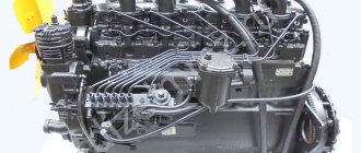
Lubrication system for GAZ-69, GAZ-69A, GAZ-63 and GAZ-51A engines
The engines of GAZ-69, GAZ-69A, GAZ-63 and GAZ-51A cars have a combined lubrication system made according to the same scheme.
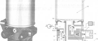
Oil from the sump through the oil receiver 20 is taken by pump 2 and pumped through a coarse filter into the main line located along the cylinder block. From the main line, oil is directed through transverse channels in the block to the main and connecting rod bearings of the crankshaft, as well as to the camshaft bearings and valve lifters. Unlike the engine of the GAZ-69 car, the pushers of the engine of the GAZ-63 car are lubricated with oil that collects in special pockets.
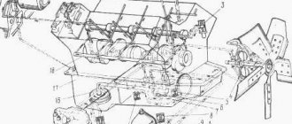
Rice. Engine lubrication diagram for a GAZ-69 car: a - diagram of the engine lubrication system: b - camshaft cam lubrication diagram; 1 — lubrication tube for camshaft drive gears; 2 - oil pump; 3 - pressure reducing valve; 4 — fine filter; 5 — filter element; 6 — filter cover bolt; 7 — drain plug; 8 - camshaft; 9 — oil filler pipe; 10 — oil radiator; 11 - bypass valve; 12 — coarse filter roller handle; 13 — oil seal nut; 14 — oil radiator valve; 15 — oil pressure indicator sensor; 16 — filter plates; 17 — coarse filter housing; 18 — drain plug; 19 — cleaning plates; 20 — floating oil receiver; 21 - drain plug
The engine cylinders and camshaft lobes are lubricated by oil released from holes in the lower connecting rod heads. The camshaft drive gears are lubricated by oil flowing from the camshaft bearing through tube 1. The remaining parts are lubricated by gravity and splashing.
An oil pressure indicator sensor 15 is installed on the coarse filter. Fresh oil is poured through pipe 9.
The lubrication system of the engines of these cars has an oil radiator 10, which is turned on using valve 14. In the engine of the GAZ-63 car, oil enters the radiator only when the pressure in the lubrication system is above 1 kg/cm2. If the pressure is less, the safety valve stops the oil circulating through the radiator.
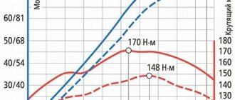
The pressure in the lubrication system of the engines of these cars should be 2-4 kg/cm2 when driving at a speed of 50 km/h. A pressure drop below 1 kg/cm2 at medium crankshaft speeds indicates a malfunction in the lubrication system. Operating the engine at this pressure is unacceptable.
How to increase oil pressure in an internal combustion engine. 406, etc.
Nowadays you can find a huge amount of goods. It can be divided not only by quality, but also by cost. It is worth noting that this also applies to the automotive market. After all, every manufacturer wants to make a huge profit from sales and invest less money. During the Soviet era, the ZIL 130 engine, which was distinguished by its good strength and durability, gained enormous popularity. When installing pump 514, the hex drive must be ground down by 6 mm. or place a thicker gasket under the cover.
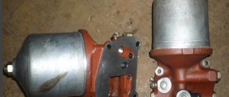
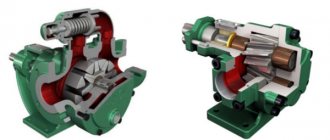
Oil pump and oil cooler of a ZIL-130 car engine
What is the purpose of the oil pump in the engine lubrication system?
The oil pump serves to force oil supply to the most heavily loaded parts of the engine, as well as to its cleaning and cooling devices.
What type of oil pumps are used on car engines?
Automotive engines use gear-type oil pumps, one- and two-section. They are installed in the crankcase (GAZ-24 Volga, KamAZ-5320 cars) or outside on the crankcase (GAZ-53A, ZIL-130 cars). Regardless of the location of the pump, its suction cavity is necessarily connected by a pipeline to an oil intake immersed in oil or (less often) floating on the surface of the oil.
How does the oil pump of a ZIL-130 car engine work and work?
The two-section oil pump of the ZIL-130 car engine (Fig. 37, a) has a housing consisting of three parts - the upper 15 (Fig. 37, b) for supplying oil to the main oil line, the lower 1, supplying oil to the oil cooler, and middle 18, in which the pressure reducing valve is located. It consists of a plunger 5 with a spring 6, closed by a screw plug 7, and serves to protect it from rupture when the pressure increases excessively (starting a cold engine). When the pressure exceeds 0.32 MPa, the valve opens and transfers oil from the pump discharge cavity to the inlet cavity. The parts of the housing are connected to each other by bolts 25 with washers 24 through sealing gaskets 16 and 19 and guide pins 4. A sealing gasket 14 is also installed between the pump housing and the crankcase. A shaft 12 with a centering sleeve 11 is mounted in the housing. It is driven by the engine camshaft . Spur gears 17 (upper) and 20 (lower) sections are secured to the shaft using keys 10 and retaining rings 13. Driven gears 8 and 3 are in constant mesh with these gears, freely mounted on axes 9 and 2. A bypass ball valve 23 is installed in the body of the lower section, loaded with a spring 22 and closed with a threaded plug 21. It automatically turns off the flow of oil to the oil filter when its pressure is below 0.12 MPa, so that all the oil is supplied to lubricate engine parts.